1
RNAS-1200 Series User’s Manual
Fourth Edition, May 2014
www.moxa.com/product
© 2014 Moxa Inc. All rights reserved.
RNAS-1200 Series User’s Manual
The software described in this manual is furnished under a license agreement and may be used only in accordance with
the terms of that agreement.
Copyright Notice
© 2014 Moxa Inc. All rights reserved.
Trademarks
The MOXA logo is a registered trademark of Moxa Inc.
All other trademarks or registered marks in this manual belong to their respective manufacturers.
Disclaimer
Information in this document is subject to change without notice and does not represent a commitment on the part of
Moxa.
Moxa provides this document as is, without warranty of any kind, either expressed or implied, including, but not limited
to, its particular purpose. Moxa reserves the right to make improvements and/or changes to this manual, or to the
products and/or the programs described in this manual, at any time.
Information provided in this manual is intended to be accurate and reliable. However, Moxa assumes no responsibility for
its use, or for any infringements on the rights of third parties that may result from its use.
This product might include unintentional technical or typographical errors. Changes are periodically made to the
information herein to correct such errors, and these changes are incorporated into new editions of the publication.
Technical Support Contact Information
www.moxa.com/support
Moxa Americas
Moxa China (Shanghai office)
Toll-free: 1-888-669-2872
Toll-free: 800-820-5036
Tel:
+1-714-528-6777
Tel:
+86-21-5258-9955
Fax:
+1-714-528-6778
Fax:
+86-21-5258-5505
Moxa Europe
Moxa Asia-Pacific
Tel:
+49-89-3 70 03 99-0
Tel:
+886-2-8919-1230
Fax:
+49-89-3 70 03 99-99
Fax:
+886-2-8919-1231
Moxa India
Tel:
+91-80-4172-9088
Fax:
+91-80-4132-1045
Table of Contents
1.
Introduction ...................................................................................................................................... 1-1
Overview ........................................................................................................................................... 1-2
Package Checklist ............................................................................................................................... 1-2
Product Features ................................................................................................................................ 1-3
Hardware Specifications ...................................................................................................................... 1-3
Software Specifications........................................................................................................................ 1-4
2.
Hardware Introduction...................................................................................................................... 2-1
Hardware Layout ................................................................................................................................ 2-2
Front View .................................................................................................................................. 2-2
Rear View ................................................................................................................................... 2-2
Dimensions ........................................................................................................................................ 2-3
LED Indicators .................................................................................................................................... 2-4
Real Time Clock .................................................................................................................................. 2-4
3.
Hardware Connection Description ..................................................................................................... 3-1
Installing the RNAS-1200..................................................................................................................... 3-2
Connecting the Power ......................................................................................................................... 3-2
Connecting to the Network................................................................................................................... 3-2
Installing the Storage Drive ................................................................................................................. 3-3
Installing the RNAS-1200 into a Wall-mounting Frame ............................................................................ 3-4
RNAS-1200 Administration................................................................................................................... 3-5
4.
Wizard Configuration Scenarios ........................................................................................................ 4-1
Creating a Shared Network Folder......................................................................................................... 4-2
Enabling Data XPro ............................................................................................................................. 4-5
5.
Modify System Settings ..................................................................................................................... 5-1
System Information ............................................................................................................................ 5-2
General Settings ......................................................................................................................... 5-3
Time .......................................................................................................................................... 5-4
Firmware Upgrade ....................................................................................................................... 5-4
Subsystem Events ....................................................................................................................... 5-6
Password.................................................................................................................................... 5-7
6.
Modify Network Settings ................................................................................................................... 6-1
Network Settings ................................................................................................................................ 6-2
Ethernet ..................................................................................................................................... 6-2
SNMP ......................................................................................................................................... 6-5
FTP/SSH................................................................................................................................... 6-16
7.
Managing Drives and Storage............................................................................................................ 7-1
Checking Drive Status, Capacity, and Health .......................................................................................... 7-2
S.M.A.R.T Information ................................................................................................................. 7-3
Formatting Disks and Arrays ......................................................................................................... 7-3
Scanning Disks and Arrays ........................................................................................................... 7-4
Viewing Disk Volumes .................................................................................................................. 7-4
Creating a Disk Volume ................................................................................................................ 7-4
Enabling Disk Encryption .............................................................................................................. 7-6
8.
SAMBA: Managing Users and Directories ........................................................................................... 8-1
SAMBA .............................................................................................................................................. 8-2
Adding Users .............................................................................................................................. 8-2
User Accounts Management .......................................................................................................... 8-4
Deleting Users ............................................................................................................................ 8-5
Creating Directories ..................................................................................................................... 8-5
Editing and Deleting Directories .................................................................................................... 8-6
9.
Vibration and Temperature Protections............................................................................................. 9-1
Configuring Data XPro™ ...................................................................................................................... 9-2
Vibration Protection ..................................................................................................................... 9-2
High Temperature Protection ........................................................................................................ 9-3
10. Enabling Fast Synchronizations for RAID 1 ..................................................................................... 10-1
Enabling Fast Synchronizations........................................................................................................... 10-2
11. Enabling IHS™................................................................................................................................. 11-1
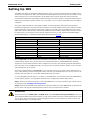
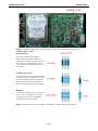
Setting Up IHS ................................................................................................................................. 11-2
Hardware Version 1.1 IHS Settings ..................................................................................................... 11-4
12. Setting Up Network Shares ............................................................................................................. 12-1
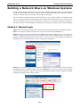
Building a Network Share on Windows Systems .................................................................................... 12-2
Method 1: Manual Login ............................................................................................................. 12-2
Method 2: Building a Permanently Mapped Share .......................................................................... 12-3
Deleting a Permanently Mapped Share ......................................................................................... 12-4
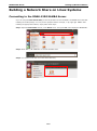
Building a Network Share on Linux Systems ......................................................................................... 12-5
Connecting to the RNAS-1200 SAMBA Server................................................................................ 12-5
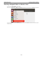
Deleting a Mapped Folder on Ubuntu Linux ................................................................................... 12-7
1
1.
Introduction
Thank you for choosing Moxa’s RNAS-1200 Network Attached Storage (NAS) system. The RNAS-1200 Series is
designed to provide high performance, high reliability and high capacity storage for video surveillance or other
industrial applications.
This manual details the hardware, installation, and software configuration, so that users can easily start using
RNAS-1200 devices.
The following topics are covered in this chapter:
Overview
Package Checklist
Product Features
Hardware Specifications
Software Specifications
RNAS-1200 Series
Introduction
Overview
Moxa's RNAS-1200 Series are network-attached storage (NAS) units designed to provide high performance,
high reliability, and high capacity data storage in harsh industrial environments.
The RNAS-1200 Series is built with a fanless, thermally efficient, dust- and water-protected IP 54-rated chassis.
This sealed enclosure eliminates internal fans as a point of critical system failure, protecting the internals from
dust and splashed water. These devices are further compliant with the essential sections of EN 50155 covering
operating temperature, power input voltage, power surges, ESD, and vibration, ensuring RNAS-1200 devices
will operate reliably under the temperature and vibration extremes common to rolling stock.
The RNAS-1200 Series also comes with Moxa's Intelligent Heating Solution™ (IHS) and Data XPro™
technologies. IHS automatically heats the system to ensure reliable operation even in extremely low
temperatures, while the Data XPro™ utility provides intelligent data and drive protections against extremes of
heat and vibration. In addition, the series’ remarkably fast array synchronizations at last make the full data and
hardware redundancies of RAID 1 a feasible alternative for industrial applications, while the two Gigabit PoE+
network interfaces provide not only network redundancy, but also a highly efficient, fully redundant power
supply over the same set of wires, as well.
The RNAS-1200 Series combines simple configuration and multiple data and hardware redundancies in a
compact, durable, fanless chassis ideal for industrial environments where temperature and vibration are a
concern. Whether for video surveillance of rolling stock or remote site storage of other logged data, the
RNAS-1200 Series of rugged NAS is your best choice for industrial-strength data storage.
Package Checklist
The RNAS-1200 Series includes the following models:
RNAS-1201-T: Network-attached storage with 2 M12 Gigabit PoE+ LAN ports, -40 to 70°C temperature
tolerance (operating)
RNAS-1211-T: Network-attached storage with 2 M12 Gigabit PoE+ LAN ports, -40 to 70°C temperature
tolerance (operating), and 2 pre-installed 100 GB hard disks
NOTE
Conformal coating is available on request.
Each model is shipped with the following items:
NOTE
•
RNAS-1200 storage appliance
•
Wall mounting kit
•
Documentation and software CD
•
Quick installation guide (printed)
•
Warranty card
Please notify your sales representative if any of the above items are missing or damaged.
1-2
RNAS-1200 Series
Introduction
Product Features
•
Onboard Marvell 1.0 GHz processor
•
Built-in 512 MB DDRII memory
•
2 Gigabit Ethernet ports for network redundancy
•
2 pre-installed 100 GB disks (RNAS-1211-T model only)
•
Compliant with EN 50121-4 and essential sections of EN 50155
•
IEC 61373 certified for shock and vibration resistance
•
JBOD, BIG, RAID 0, and RAID 1 disk architectures
•
Intelligent Heating Solution™ (IHS) technology for reliable operation
•
Data XPro™ utility for protection of data against extreme heat and vibration
•
Fast RAID 1 synchronizations
Hardware Specifications
Computer
CPU: Onboard Marvell 1.0 GHz 88F6281
DRAM: 512 MB DDRII
Flash Memory: Onboard 2 GB USB DOM for OS storage
Storage
RNAS-1201-T: 2.5-inch HDD bay x 2, reserved for storage expansion
RNAS-1211-T: 100 GB HDD x 2 pre-installed
Ethernet Interface
LAN: 2 auto-sensing 10/100/1000 Mbps ports (M12)
IHS Control
IHS Function Control: Temperature reading, power output control
LEDs
System: RAID, Ready, HDD1, HDD2
LAN: 100M/Link x 2, 1000M/Link x 2
Physical Characteristics
Housing: Aluminum
Weight: 1.98 kg (RNAS-1201-T)/2 kg (RNAS-1211-T)
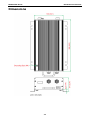
Dimensions: 252 x 130 x 57 mm (9.92 x 5.12 x 2.24 in)
Mounting: Wall
IP Rating: IP 54
Environmental Limits
Operating Temperature: -40 to 70°C (-40 to 158°F)
Storage Temperature: -40 to 85°C (-40 to 176°F)
Ambient Relative Humidity: 5 to 95% (non-condensing)
Anti-vibration: EN 50155 standard
Anti-shock: EN 50155 standard
Conformal Coating: Available on request
Power Requirements
Input: PoE (IEEE 802.3af) or PoE+ (IEEE 802.3at)
Note: If the RNAS-1200 has connected to a PoE switch, and T1 mode has been configured, it can only boot up
when the ambient temperature is above 0°C.
Standards and Certifications
Safety: UL 60950-1
EMC: EN 55022 Class A, EN 61000-3-2, EN 61000-3-3, EN 55024
Rail Traffic: EN 50155, EN 50121-3-2, EN 50121-4, IEC 61373
1-3
RNAS-1200 Series
Introduction
Green Product: RoHS, CRoHS, WEEE
EMI: FCC Part 15 Subpart B Class A, CISPR 22:2008
Warranty
Warranty Period: 5 years (storage drive not included)
Details: See www.moxa.com/warranty
Note: These hardware specifications describe the network-attached storage unit itself, but not its accessories.
In particular, the wide temperature specification does not apply to accessories such as power adaptors and
cables.
Software Specifications
Operating System
System Platform: Linux 2.6 pre-installed
Network
IP Settings: Fixed IP, DHCP
Redundancy: Port trunking/NIC teaming
System Management
Firmware Upgrade: Can be run via web interface
System Bootup: Can be observed by LED indicators for system status
HDD Failure Status: Can be observed by LED indicators
Disk Management
JBOD: Two drives operate independently
Spanning Big: Two drives are merged into a single, oversized virtual drive
RAID 0: Two drives are merged, with data striped across the disks to improve data access times
RAID 1: Two drives operate as a single drive, with full hardware and data redundancy
RAID 1 Data Recovery: RAID 1 allows full data recovery upon failure or replacement of any single drive.
Data Protection
Vibration Protection: Non-volatile storage buffer for temporary drive shut-downs due to strong vibration
Temperature Protection: Auto-shutdown, non-volatile storage buffer for temporary shutdowns, and
automatic system heating utility for below-zero environments
Fast Sync.: 15 second drive synchronizations in RAID 1 mode
SNMP Management
System: Standard MIB-II (RFC 1213), plus additional Moxa features that include: NTP, time zone, and time
display management; channel bonding and IP configuration; management of SSH, FTP, and DNS; and
configuration of SNMP agents and traps.
1-4
2
2.
Hardware Introduction
This chapter describes the hardware introduction, including the appearance of the RNAS-1200 Series, product
dimensions, and LED indicators.
The following topics are covered in this chapter:
Hardware Layout
Front View
Rear View
Dimensions
LED Indicators
Real Time Clock
RNAS-1200 Series
Hardware Introduction
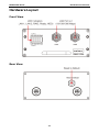
Hardware Layout
Front View
Rear View
2-2
RNAS-1200 Series
Hardware Introduction
Dimensions
2-3
RNAS-1200 Series
Hardware Introduction
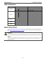
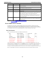
LED Indicators
LED Name
LED Color/Status
LED Function
Green
Ready
RAID
LAN (1, 2)
HDD1
HDD2
Power is on and functioning normally
On 1 sec
Off 1 sec
Resetting to default
On 5 sec
Off 5 sec.
IHS pre-heating
Off
Power error, or off
Red
RAID recovery fails
On 1 sec
Off 0.5 sec
RAID disk is recovering
On 5 sec
Off 1 sec
HDD1 fails
On 10 sec Off 1 sec
HDD 2 fails
On 15 sec Off 1 sec
HDD 1 and HDD2 fail
On 1 sec
HDD overheated; no power
Off 5 sec
Off
RAID recovery complete, or no activity
Green
100 Mbps Ethernet mode
Yellow
1000 Mbps Ethernet mode
Off
No Ethernet activity
Yellow
Drive 1 is writing/reading data
Off
No activity
Yellow
HDD2 is writing/reading data
Off
No activity
Real Time Clock
The embedded computer’s real-time clock is powered by a lithium battery. We strongly recommend that you
NOT replace the lithium battery on your own. If the battery needs to be changed, contact the Moxa RMA service
team at http://www.moxa.com/rma/about_rma.aspx.
WARNING
There is a risk of explosion if the wrong type of battery is used. To avoid this potential danger, always be sure
to use the correct type of battery. Contact the Moxa RMA service team if you need to replace your battery.
Caution
There is a risk of explosion if the battery is replaced by an incorrect type. Dispose of used batteries according
to the manufacturer’s instructions, and be aware that local ordinances may require special handling as a
hazardous substance.
2-4
3
3.
Hardware Connection Description
In this chapter, we show how to connect the RNAS-1200 to the network and to various devices.
The following topics are covered in this chapter:
Installing the RNAS-1200
Connecting the Power
Connecting to the Network
Installing the Storage Drive
Installing the RNAS-1200 into a Wall-mounting Frame
RNAS-1200 Administration
RNAS-1200 Series
Hardware Connection Description
Installing the RNAS-1200
Wall or Cabinet Mounting
The RNAS-1200 provides two mounting kits, for either walls or cabinets.
Attach the brackets to either side of the chassis with the included screws
Connecting the Power
To power on the RNAS-1200, simply connect the Ethernet port to any Ethernet switch that supports PoE or
PoE+. Once the system is fully powered and initialized, the Ready LED will light up.
ATTENTION
If the RNAS-1200 has connected to a PoE switch, and T1 mode has been configured, it can only boot up when
the ambient temperature is above 0°C.
Connecting to the Network
Plug your network cable into the RNAS-1200’s Ethernet port. The other end of the cable should be plugged into
your Ethernet network. When the cable is properly connected, the LEDs on the RNAS-1200’s Ethernet port will
glow to indicate a valid connection.
The 10/100/1000 Mbps Ethernet LAN port uses 8-pin M12 connectors. The following diagram shows the pinouts
for these ports.
3-2
RNAS-1200 Series
Hardware Connection Description
No.
10/100 Mbps
1000 MBps
1
–
TRD3+
2
–
TRD4+
3
–
TRD4-
4
ERx-
TRD1-
5
ETx+
TRD2+
6
ERx+
TRD1+
7
–
TRD3-
8
ETx-
TRD2-
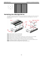
Installing the Storage Drive
The RNAS-1200 Series has two SATA connectors for two SATA disks. The RNAS-1211 model comes with two
pre-installed 100 GB hard disk drives. . To install SATA storage drives into the RNAS-1201, refer to the
following figures.
Step 1: Remove the two screws on the front panel.
Step 2: Remove the four screws on the rear panel.
Step 3: Remove the top cover of the RNAS-1200.
Step 4: Remove the four screws on the drive’s mounting tray, and remove the tray from the RNAS.
Step 5: Situate the drive so that its four holes match up with the tray’s mounting holes.
Step 6: Affix the drive to the mounting tray using the four screws you have just removed.
Step 7: Re-affix the mounting tray (with the now mounted storage drive on top) to the RNAS drive slot.
Step 8: To install the second drive, repeat steps four through seven. .
Step 9: Secure the enclosure by reversing the first 3 steps of this procedure.
3-3
RNAS-1200 Series
Hardware Connection Description
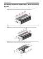
Installing the RNAS-1200 into a Wall-mounting
Frame
An optional wall-mounting kit is available for the RNAS-1200. To install, follow the steps below.
Step 1: Remove the eight screws that fasten the wall-mount ears to the RNAS-1200.
Step 2: Replace the wall-mount ears with two rails (which run the length of the device) using the same eight
screws.
Step 3: Fasten the faceplate brackets to the front panel of the RNAS using the four screws provided.
Step 4: Align the tracks with the fixed rails within the wall-mounting frame, slide the RNAS-1200 into the tray,
and fasten the device using the brackets you have just affixed to the front panel.
3-4
RNAS-1200 Series
Hardware Connection Description
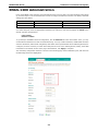
RNAS-1200 Administration
Power up the RNAS-1200 computer and verify that the power source is ready. Once the operating system boots
up, the first step is to use the administrator account to configure the Ethernet interface. The factory default IP
settings are show below:
Default IP Address
Netmask
LAN1
192.168.3.127
255.255.255.0
LAN2
192.168.4.127
255.255.255.0
You may use a web browser to access the RNAS-1200’s configuration wizard. Simply connect to the RNAS-1200
over either LAN port, enter the appropriate IP address into a browser, and when prompted use admin as the
default username and password.
Login: admin
Password: admin
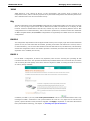
To go directly to the RNAS-1200’s IP configuration, click the Network tab in the main toolbar. There, you may
set the Ethernet interfaces for static or DHCP addressing. To set up a static IP address, disable DHCP and then
enter the IP address, subnet mask and gateway information in the specified fields. If two different gateways are
configured, it will be necessary to select which LAN port will serve as the default gateway. Finally, enter DNS
information in the bottom section of the page. When finished, click Apply to complete.
The networking configuration interface is shown on the following page of this installation guide, with the main
IP addressing parameters highlighted.
3-5
4
4.
Wizard Configuration Scenarios
This chapter describes how to use the scenario wizard for basic configuration of the RNAS-1200. Users may use
the wizard to quickly configure the device for some commonly used applications.
The following topics are covered in this chapter:
Creating a Shared Network Folder
Enabling Data XPro
RNAS-1200 Series
Wizard Configuration Scenarios
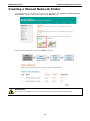
Creating a Shared Network Folder
To create a network directory that may be shared over the network, click Scenario 1: Create a network
shared folder. The link is located at the bottom of the Welcome page.
Review the drive information, and then click Next to continue.
ATTENTION
If you want to use DataXPro, you have to enable it before you create a shared network folder.
4-2
RNAS-1200 Series
Wizard Configuration Scenarios
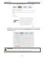
You will be presented with the RNAS Drive Architectures page, from within the DISK tab.
Click Next after you have selected the drive architecture and enabled or disabled disk encryption. Depending
on the architecture you select, the system may take a long time to complete the procedure. You may get a basic
idea of how much longer the procedure will take using the Formatting Progress bar at the bottom of the Disk
Operation Progress page.
IMPORTANT!
The RNAS-1200 drive architecture wizard will automatically format your drives with an ext4 file system. After
building a drive architecture, it is not necessary for users to re-format the drives.
4-3
RNAS-1200 Series
Wizard Configuration Scenarios
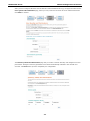
After you have configured the basic drive architecture and formatted the drive(s), the page will redirect to the
User Quotas and Permissions page, where you may create user accounts to access network directories.
Click Next to continue.
The Directory Labels and Permissions page lets you create a network directory and configure its access
permissions. Changes to directory permissions here will be automatically reflected in the relevant user
accounts. Click Next when you have completed your configuration.
4-4
RNAS-1200 Series
Wizard Configuration Scenarios
Enabling Data XPro
The Data XPro™ utility is one of the RNAS-1200’s key features; it helps prevent data loss from harsh vibration
and hardware destruction from extreme temperatures. To configure Data XPro, click Scenario 2: Enable Data
XPro to continue.
On the Data XPro page you may review the current usage capacity of the Data XPro data buffer. During times
of high vibration this data buffer is used to store deferred data accesses. The data buffer is not part of the
high-temperature protection procedure. During extremely high temperatures, Data XPro will cut power to the
drives to protect against catastrophic hardware failure. The temperature threshold at which that happens is
also configured here.
WARNING
The temperature protection cutoff will result in an effective shutdown of the entire system. This includes the
data buffer. No data will be stored in the buffer once the drives power down. Use this feature with
caution: it is only intended for extreme temperature highs that are a significant threat to system survival.
4-5
5
5.
Modify System Settings
This chapter describes how to configure and modify the system settings.
The following topics are covered in this chapter:
System Information
General Settings
Time
Firmware Upgrade
Subsystem Events
Password
RNAS-1200 Series
Modify System Settings
System Information
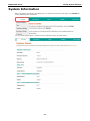
When successfully connecting to the RNAS-1200, you will be directed to the main page. Click SYSTEM for
viewing detailed system information.
You may check system status, a system overview, Data XPro status, and disk status.
5-2
RNAS-1200 Series
Modify System Settings
General Settings
Click General Settings from the SYSTEM tab. Here you may configure the host name and the web server
listening port for the RNAS-1200. This is the web server that serves the RNAS web configuration interface.
Resetting this entry will result in a restart of the web interface, after which connection to the RNAS
configuration UI will be broken. To reconnect, you will need to use your HTML browser to log on to the
configuration interface over the port you have just configured (192.68.XX.XXX:YYY, where Y is the newly
configured port number and XX.XXX is the user-configured IP address). To set your changes, click Apply.
Reset to Default
In addition, you may reset the entire system configuration to default values by applying the Reset to Default
option. Select Keep Network Settings if you wish to reset the rest of the system but continue to use the
current network settings. You may also reset the system to factory defaults by using a screwdriver (or other
pointed tool) by push the Reset to Default button (on the rear panel of the RNAS-1200) and holding it for five
seconds.
Please note that all data will be erased after resetting to default.
5-3
RNAS-1200 Series
Modify System Settings
Time
Select Time from SYSTEM tab to configure the system time and clock.
You may select a base time zone from the Timezone drop-down menu. When finished, click Apply. Next, to
configure date and time you may choose either Manual Setting to set the time by hand, or to automatically
synchronize with an Internet time server (i.e., an NTP server). Click Apply to complete the configuration.
Firmware Upgrade
The Firmware Upgrade page is located under the SYSTEM tab.
5-4
RNAS-1200 Series
Modify System Settings
This page allows you to automatically download new versions of the RNAS-1200 firmware from the Moxa
website. To upgrade your firmware, please follow the steps listed exactly, and be careful to note the warnings.
Be sure you have the correct version of the firmware and do not power off the RNAS-1200 during the upgrade
process. When finished, click UPDATE THE SYSTEM to complete.
WARNING
Please note that the firmware upgrade will erase all data in the RNAS-1200. Back up any important data you
wish to keep before undertaking the firmware upgrade.
5-5
RNAS-1200 Series
Modify System Settings
Subsystem Events
Select Subsystem Events from SYSTEM tab.
This allows users to monitor three RNAS-1200 subsystems in real time. The three main subsystems are the
drive activity (Disk), SAMBA activity (SAMBA), and general operating system events (System).
5-6
RNAS-1200 Series
Modify System Settings
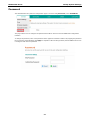
Password
The administration UI’s password configuration page is accessed using Password, in the SYSTEM tab.
This page allows users to configure the password that will be used to access the RNAS web configuration
interface.
To change the password, enter a new password in the upper box and then confirm it by retyping the password
the in lower box. When finished, click Apply to complete. If the two strings match, then the RNAS-1200 is now
reconfigured with the new password.
5-7
6
6.
Modify Network Settings
This chapter describes how to configure or modify the network settings of the RNAS-1200 models.
The following topics are covered in this chapter:
Network Settings
Ethernet
SNMP
FTP/SSH
RNAS-1200 Series
Modify Network Settings
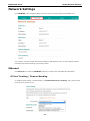
Network Settings
Click NETWORK in the navigation ribbon to view the current network settings for the RNAS-1200.
The summary overview includes the network settings for both Ethernet ports, as well as default gateway
information and channel bonding / port trunking status.
Ethernet
Click Ethernet from within the NETWORK submenu to configure the basic Ethernet LAN settings.
IP Port Trunking / Channel Bonding
To enable IP port trunking / channel bonding, click Enable Network Port Trunking. Then, select the port
trunking mode you wish to use.
6-2
RNAS-1200 Series
Modify Network Settings
There are seven modes for IP bonding / port trunking. Below you will find summaries of their weak points and
strong points. In most cases, mode five—IEEE 802.3ad, or LACP—will probably be the preferred mode.
1.
Balance-rr (Round-Robin)
Round robin mode transmits network packets in sequential order from the first available network interface
(NIC slave) through the last. This mode provides rudimentary load balancing and high fault tolerance. If a
switch is being used, an appropriate switch configuration will be required. Be warned: some switches do
not support balance-rr. If the bandwidth of one of the NICs deteriorates, then the total bandwidth of the
interface drop an equal amount.
2.
Active Backup (Failover)
In failover mode, only one NIC in the bond is used to actively transmit packets. The alternate NIC becomes
active if, and only if, the default fails. The single, logical interface's MAC address is externally visible on
only one NIC (port) at a time, to avoid distortion in network switches. This mode provides strong
redundancy and high fault tolerance.
3.
Balance-xor
Balance-xor balances outgoing traffic across the active ports using hashed protocol headers. This lets it
accept incoming traffic from either port. The hash used to transmit network packets is [(source MAC
address XOR'd with destination MAC address) modulo NIC slave count]. This mode provides high
load balancing and high fault tolerance.
4.
Broadcast
This mode does not provide load balancing: both network interfaces are used to transmit identical packets.
This provides high fault tolerance.
5.
IEEE 802.3ad (Dynamic Link Aggregation, or LACP)
This is the most reliable and effective interface bonding mode; it uses hashed protocol headers that enable
it balance outgoing traffic across all active ports while allowing it to accept incoming traffic from any active
port. LACP automatically creates aggregation groups that share the same speed and duplex settings.
According to the standard, frames must be delivered in order and connections may not receive packets out
of order. Minimal switch configuration is required.
6.
Balance-tlb (Adaptive Transmit Load Balancing)
This mode balances the outgoing traffic according to peer. Outgoing network traffic is distributed according
to the current load (computed relative to the speed) on each network interface. Incoming traffic is not
balanced: all incoming traffic is received by one designated network interface. If this receiving interface
fails, the other will take over the MAC address of the failed receiver.
7.
Balance-alb (Adaptive Load Balancing)
This mode is essentially the same as balance-tlb but it also balances incoming traffic, as well. Balance-alb
is balance-tlb plus receive load balancing (rlb). The bonding driver intercepts ARP replies sent by the local
system (on their way out) and overwrites the source hardware address with the unique hardware address
of an NIC in the logical interface so that different network-peers will use different MAC addresses for their
network traffic. It does not require any special network switch support.
6-3
RNAS-1200 Series
Modify Network Settings
Overview of Ethernet LAN Settings
Ethernet 1 and Ethernet 2: These interfaces may be independently configured for either DHCP or static
addressing. For static IP addresses, provide the address, subnet mask, and gateway information.
Default Gateway: In configurations where two gateways are configured, use this to select the interface you
want to use as the default gateway. This may be left disabled if only one gateway is configured.
DNS: Check if you want to manually configure a DNS server.
When finished, click Apply to implement the configuration.
6-4
RNAS-1200 Series
Modify Network Settings
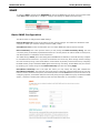
SNMP
To configure SNMP, navigate to the NETWORK tab, then to the SNMP tab, from which you may further select
either Basic SNMP configuration, or Trap (to configure the settings for SNMP alarms and traps).
Basic SNMP Configuration
This allows users to configure basic SNMP settings.
Network Manager IP: Provide the IP address for the network manager. This will be the IP address of the
computer on which your network manager software (NMS) resides.
Send/Receive Port: Set the communication port over which SNMP data will be sent and received.
Read Community: This is the input box where you may change the Read Community String. The read
community string is essentially a password that works as a security feature to make it harder for anonymous,
untrusted systems to read data from the local device.
The default string is Public; this is the setting which all SNMP devices default to, and it will allow any computer
to read data from the local device. To provide the most basic level of security, Moxa strongly advises changing
the read community string. Users should build a virtual network of privately connected devices by configuring
the NMS and the group of networked SNMP agents with a strong read string. On the RNAS-1200, this is done
by inputting your chosen string into the Read Community input box and clicking Apply.
Read/Write Community: This is the input box where you may change the string that identifies the
Read/Write Community. The read/write community string is essentially a password that works as a security
feature to make it harder for anonymous, untrusted systems to read or write data from/to the local device. By
configuring a private, undisclosed read/write community string among an NMS and a group of networked SNMP
agents, a network of trusted peers that may read and write information to one another is created.
6-5
RNAS-1200 Series
Modify Network Settings
Moxa strongly recommends changing the read/write community to a cryptographically strong, private key.
Public is the default, and this will allow any computer to read and write data from the local device. To set up
a cryptographically strong private string on the RNAS-1200, enter your chosen string into the Read/Write
Community input box and click Apply.
IMPORTANT!
Strong cryptographic strings should be at least 8 random characters (i.e., not in a dictionary) and include
capitalized letters and symbols. Do not forget to store your community keys in a secure location.
SNMP MIB Download
The RNAS-1200 comes with two MIB files: a standard RFC 1213 MIB-II file, and a custom Moxa MIB file. Our
custom MIB file provides extra features for our RNAS users that include increased interoperability for scripts
and custom software, as well as custom control features for better remote management.
As new features are created, Moxa’s proprietary MIB file will occasionally need to be updated. To get the latest
MIB file from the Moxa website, simply click Download (at the bottom of the page, in the screenshot above)
to download the file to your local computer.
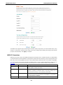
SNMP Traps
This page allows users to configure SNMP trap types and settings (screenshot on following page).
In Trap Settings, you may choose to set the following parameters:
•
Version: Select the SNMP version by which your traps will be defined. This is an available option for
systems compatible only with traps as defined in SNMP v1.
•
Server Port: Enter the number of the port through which your SNMP agent and NMS will communicate.
•
Trap IP (#1 to #3): Enter the IP addresses to which the traps will be delivered; up to three different SNMP
clients are allowed.
•
Trap Community String: Enter either public or private for the trap community string.
•
Notify Interval: Enter the interval time for sending the notification SNMP trap message to the trap IP
address.
When finished, click Apply to complete the configurations.
6-6
RNAS-1200 Series
Modify Network Settings
The RNAS-1200 supports traps for three types of events: system temperature, hard drive health status (using
S.M.A.R.T. summaries), and disk volume usage. Users may configure these settings according to their specific
purposes. When finished, click Apply to complete.
MIB-II Overview
MIB-II is the second version of the SNMP management information base, as defined by RFC 1213-MIB. MIB-II
is a standardized hierarchical database of programming objects that form the basic group of management tools
that every device running SNMP must share. These objects define what information is accessible using SNMP.
The following table gives a brief description of MIB-II groups. For more detailed explanations, please refer to
RFC 1213, which gives detailed definitions and parameters for all basic OIDs and OID groups in MIB-II.
Subtree Name
OID
Description
system
1.3.6.1.2.1.1
The system group is a list of objects that relate to system processes
interfaces
1.3.6.1.2.1.2
such as uptime, contact, and name.
The interfaces group manages and monitors the status of data
interfaces, reporting on interface status, or reporting activity such as
octets sent and received, errors, discards, and the like.
at
1.3.6.1.2.1.3
The address translation (at) group should be considered a legacy
component included only for backward compatibility. It is planned on
being eliminated from MIB-III.
ip
1.3.6.1.2.1.4
The IP group provides management objects for monitoring, reporting,
6-7
RNAS-1200 Series
Modify Network Settings
and controlling many elements of IP and IP routing.
icmp
1.3.6.1.2.1.5
The ICMP group monitors internal system reports of IP errors,
discards, and the like.
tcp
1.3.6.1.2.1.6
udp
1.3.6.1.2.1.7
egp
1.3.6.1.2.1.8
This group reports on TCP states, returning whether the interface is
closed, listening, synSent, and so forth.
The UDP group returns statistics on UDP performance.
The EGP group provides objects useful for EGP monitoring, like an EGP
neighbor table.
transmission
1.3.6.1.2.1.10
MIB-I lacked any way of distinguishing types of transmission media.
While the transmission group currently has no defined objects, this
subtree allows the creation of media-specific MIBs. When
Internet-standard definitions for managing transmission media are
defined, the transmission group is used to provide a prefix for the
names of those objects.
snmp
1.3.6.1.2.1.11
The SNMP group measures SNMP performance on the local device by
logging and calculating such things as the number of SNMP packets
sent and received.
For more information, visit http://www.ietf.org/rfc/rfc1213.txt, or refer to the O’Reilly book, Essential SNMP,
available for free viewing online.
Moxa’s SNMP Control Interface
The RNAS-1200 comes with a customized MIB file that provides a proprietary monitoring and control
environment. This custom software utilizes SNMP to provide a much more convenient means of remotely
controlling and monitoring a device. Using Moxa’s SNMP control interface, you may create custom automations
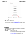
for most RNAS-1200 processes by calling SNMP objects in simple, standardized shell scripts.
Brief Introduction
Refer to the following base OIDs for the RNAS-1200 MIB subtree.
Moxa
MODULE-IDENTITY
::= { enterprises
8691}
Linux
OBJECT IDENTIFIER
::= { moxa
12
rnas1200
OBJECT IDENTIFIER
::= { Linux
1200 }
mxControlManager
OBJECT IDENTIFIER
::= { rnas1200
1
}
rnas1200Setting
OBJECT-TYPE
::= { mxControlManager 1
}
rnas1200Commit
OBJECT-TYPE
::= { mxControlManager 2
}
rnas1200Query
OBJECT-TYPE
::= { mxControlManager 3
}
}
Finally, keep in mind that for many NMS implementations, all OIDs must be appended with a final value
indicating whether it is a scalar value (0), or a columnar value (i.e., a simple table). While some NMS suites
do allow the final .0 to be dropped, it is good practice to include these values in your SNMP commands.
Currently, all of Moxa’s proprietary OIDs are scalar values, and so should be completed with a final zero (.0).
Below, a simple SNMP tree showing the relationships between the Moxa enterprise OIDs is provided.
6-8
RNAS-1200 Series
Modify Network Settings
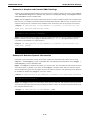
rnas1200Setting
•
A scalar SNMP object used to import the RNAS-1200 settings.
•
OID: 1.3.6.1.4.1.8691.12.1200.1.1.0
•
Note: Imported items are stored in RAM for up to 15 minutes. All imported values are committed to the
database in bulk by setting the rnas1200Commit data string to '1'. For a better understanding of the
settings query and commit process, please refer to the examples below for clarification on the syntax
and full procedure.
•
Input Syntax:
[RESOURCE_IDENTIFIER]=[VALUE]
Ex: systemResources.hostname.1=MOXA
•
Output Result:
Since the object is read-only, if you’re trying to get this object, you’ll get the
string Not available.
rnas1200Commit
•
A scalar SNMP object used to commit all settings which have been imported by the 'rnas1200Setting'
object.
•
OID: 1.3.6.1.4.1.8691.12.1200.1.2.0
•
Input Syntax:
1 = Commit all settings to the database
•
Output Result:
0 = The commit was successfully written to the database
1 = The commit failed because the database was busy. When a commit has failed,
the RNAS-1200 settings will be erased from memory and must be reloaded
before the commit may be attempted again. See the example below, Acquiring
and Committing RNAS Settings, for more details about this process.
6-9
RNAS-1200 Series
Modify Network Settings
rnas1200Query
•
A scalar SNMP object used to query an RNAS-1200 RESOURCE_IDENTIFIER. For a full list of resources
available for queries, refer to the table below, SNMP Resource Identifiers for Moxa’s SNMP Control
Interface.
•
OID: 1.3.6.1.4.1.8691.12.1200.1.3.0
•
Input Syntax:
[RESOURCE_IDENTIFIER]
Ex: systemResources.hostname.1
•
Output Result:
[RESOURCE_VALUE]
Ex: MOXA
Moxa SNMP Control Interface: Usage Examples
There are many SNMP suites, and all may be used more-or-less interchangeably. In the following example, we
use Net-SNMP syntax to demonstrate how to use SNMP to acquire information from and remotely manage a
device.
Moxa’s proprietary MIB file implements a heavily modified version of Net-SNMP that is not always intuitive. This
is because Moxa’s SNMP controls are the view layer (i.e., the user interface) of a larger MVC software
framework. The model layer of this framework is a transparent database with which the SNMP controls interact.
Thus, when the proprietary OID rnas1200Query (1.3.6.1.4.1.8691.12.1200.1.3.0) is called, the
returned resource and its associated value are being read from the relational database which forms the model
layer within the framework. When the rnas1200Commit (1.3.6.1.4.1.8691.12.1200.1.2.0) object is
called, the related resource and value are not being written directly to the system, but are instead written to the
relational database in which all system information is stored. This database is constantly being monitored by
control layer, so that when a new write to the database is completed the framework’s control layer will
automatically and immediately implement the changes in the root system.
Consequently, when using Moxa’s proprietary MIB file to control, monitor, and manage system processes, the
syntax used is slightly different than with a stock Net-SNMP implementation. Because the resources available
for management and monitoring are stored in a relational database, SNMP does not call them directly from the
root system. Instead, they are referenced as paired strings of database objects. The following example gives
a basic idea of the modified syntax; notice the data type is s, for STRING:
#snmpset [COMMAND_OPTIONS] [IP_ADDRESS] [OID] [DATA_TYPE: s, for STRING] /
[RESOURCE_IDENTIFIER=RESOURCE_VALUE]
When considering this example (and the ones below), new users of SNMP should make two notes. First, in
standard Net-SNMP syntax, OID data types are defined by tags; these tags are distinct from the command
options which modify the basic SNMP command. Common command options are delimited by hyphens (-v, -c,
-x, etc), while OID data types (i for INTEGER, s for STRING, d for DECIMAL_STRING, etc) are not
delimited by hyphens. In the three examples immediately below, the s delimiter is used to indicate that the OID
data type is a STRING.
Second, when calling an OID, a final number called the instance identifier is sometimes appended to indicate
whether the OID being called is a scalar value or is retrieving a value from within a columnar table. For Moxa’s
current implementation of the RNAS SNMP controls, all values are scalar. Thus, in all the following examples all
the instance identifiers are zero. For instance, the OID for acquiring RNAS-1200 settings is
1.3.6.1.4.1.8691.12.1200.1.1. To indicate that this is a scalar value, the instance identifier of zero may
be appended to the OID, so that the completed OID is written 1.3.6.1.4.1.8691.12.1200.1.1.0. While
the final instance identifier is not always required by NMS systems, for many it remains a required parameter
and so Moxa includes it here as an example of best practices.
6-10
RNAS-1200 Series
Modify Network Settings
Scenario A: Acquire and Commit RNAS Settings
Acquiring and committing RNAS settings is a two step process: loading a setting into memory using snmpset
+ the rnas1200Setting resource identifier OID, and then committing that setting using snmpset with the
rnas1200Commit resource identifier OID.
Step 1: Use the snmpset command to import items which you want to configure. Please note: to import more
than one item, use multiple commands. Imported settings will be stored in RAM for up to 15 minutes. If the
imported settings are not committed to the database within 15 minutes, they will be purged from memory.
#snmpset –v [SNMP_VERSION] –c [RW_COMMUNITY] [IP_ADDRESS] [rnas1200Setting OID]
[DATA_TYPE] [RESOURCE_NAME=RESOURCE_VALUE]
root@tmp# snmpset –v 2c –c admin 192.168.27.231 1.3.6.1.4.1.8691.12.1200.1.1.0 / s
“systemResources.hostname.1=MOXARNAS”
Step 2: Commit all the items you have just imported. Please note that you may use multiple commands to
import more than one item. By toggling the OID data string to 1 (….s “1”), all imported items may be
committed to the database in a single operation.
#snmpset –v [SNMP_VERSION] –c [RW_COMMUNITY] [IP_ADDRESS] [rnas1200Commit OID]
[DATA_TYPE] [TOGGLE]
root@tmp# snmpset –v 2c –c admin 192.168.27.231 1.3.6.1.4.1.8691.12.1200.1.2.0 / s
“1”
Scenario B: Retrieve System Information
Retrieving system information consists of two parts: loading the information into system memory using
snmpset + rnas1200Query resource indentifier OID, and displaying that information using snmpget +
rnas1200Query resource indentifier OID.
Step 1: Use snmpset to select the item which you want to query. This command will only load the resource
value into memory; to display it, you must use the snmpget command, below. Only one resource may be
stored in RAM at any given time. If multiple resources are called in sequence, only the last resource called will
be available for display using snmpget (see step 2, below).
#snmpset –v [SNMP_VERSION] –c [RW_COMMUNITY] [IP_ADDRESS] [OID] [DATA_TYPE] [RESOURCE]
root@tmp# snmpset –v 2c –c admin 192.168.27.231 1.3.6.1.4.1.8691.12.1200.1.3.0 / s
“systemResources.hostname.1”
Step 2: Use snmpget to return the value of the object you have selected. This operation will only return the
value most recently acquired by the query operation just above, in step 1. If no resource has been acquired, yet,
the command will return null.
#snmpget –v [SNMP_VERSION] –c [RW_COMMUNITY] [OID]
root@tmp# snmpget –v 2c –c admin 192.168.27.231 1.3.6.1.4.1.8691.12.1200.1.3.0
6-11
RNAS-1200 Series
Modify Network Settings
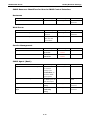
SNMP Resource Identifiers for Moxa’s SNMP Control Interface
Hostname
Item Name
Item Description
Value Description
Rules for value
systemResources.hostname.1
System hostname.
(Any String)
Up to 45
characters
Web Server
Item Name
Item Description
Value Description
webServerResources.password.1
Web server’s
(Any String)
password.
webServerResources.port.1
TCP/IP port on
Rules for value
Up to 40
characters
(IP address)
which the web
server listens.
Service Management
Item Name
Item Description
serviceResources.enable.1
Enables/disables the 0
: Disable
ftp server.
1
: Enable
Enables/disables the 0
: Disable
ssh server.
: Enable
serviceResources.enable.2
Value Description
1
Rules for value
SNMP Agent (Basic)
Item Name
Item Description
Value Description
snmpServerResources.trustHostIp.1
The IP address of
(IP Address)
Rules for value
the network
manager (the
Trusted Host) to
which the SNMP
agent reports.
snmpServerResources.port.1
The port over which (Any Number)
Any port up to
the SNMP agent will
65535
listen and report.
snmpServerResources.readCommunity.
Read Community
1
String.
snmpServerResources.readWriteCommu Read/Write
nity.1
Community
String.
6-12
(Any String)
Up to 32
characters
(Any String)
Up to 32
characters
RNAS-1200 Series
Modify Network Settings
SNMP Agent (Trap)
Item Name
Item Description
Value Description
snmpTrapResources.version.1
The SNMP.version
1
Rules for value
: first version
2c : second version
snmpTrapResources.serverPort.1
The port used by
(Any Number)
Less than 65535
SNMP traps
snmpTrapResources.trustTrapIp0.1
Trusted IP #1
(IP Address)
snmpTrapResources.trustTrapIp1.1
Trusted IP #2
(IP Address)
snmpTrapResources.trustTrapIp2.1
Trusted IP #3
(IP Address)
snmpTrapResources.community.1
The Trap
(Any String)
Community
Less than 30
characters
String
snmpTrapResources.notifyInterval.1
Notify interval for
(Any Number) (sec)
SNMP informs
Only available in 1
~ 10000
DNS Management
Item Name
Item Description
Value Description
dnsResources.enableManual.1
To enable/disable
0
: Disable
manual DNS.
1
: Enable
Rules for value
settings
dnsContainer.ip.1
The default DNS IP
(IP Address)
address
dnsContainer.ip.2
The alternate DNS
(IP Address)
IP address
System Log
Item Name
Item Description
Value Description
Rules for value
systemLogResources.maxRecord.1
The max. quantity
(Any Num)
Anything up to
of records.
6-13
65535.
RNAS-1200 Series
Modify Network Settings
Network Management
Item Name
Item Description Value Description
Rules for value
Ethernet1 (eth0)
networkResources.ip.1
IP of Ethernet 1.
(IP Address)
networkResources.subnet.1
Netmask of
(Netmask)
Ethernet 1
networkResources.gateway.1
networkResources.defaultGateway.1
Gateway of
(IP Address of
Ethernet 1.
Gateway)
Set default
0
: Disable
gateway for
1
: Enable
Enable/disable
0
: Disable
DHCP for Ethernet
1
: Enable
Ethernet 1
networkResources.enableDHCP.1
1
Ethernet2 (eth1)
networkResources.ip.2
IP of Ethernet2.
(IP Address)
networkResources.subnet.2
Netmask of
(Netmask)
Ethernet2.
networkResources.gateway.2
networkResources.defaultGateway.2
networkResources.enableDHCP.2
Gateway of
(IP Address of
Ethernet2.
Gateway)
Set Ethernet 2
0
: Disable
default gateway
1
: Enable
Enable/disable
0
: Disable
DHCP for Ethernet
1
: Enable
2.
IP Bonding1 (bond0)
networkResources.ip.3
IP of logical bond
(IP Address)
networkResources.subnet.3
Netmask of logical
(Netmask)
bond
networkResources.gateway.3
Gateway for logical (IP Address of
bond
Gateway)
networkResources.defaultGateway.3
Set gateway of
0
: Disable
logical bond
1
: Enable
To enable/disable
0
: Disable
DHCP for logical
1
: Enable
To enable/disable
0
: Disable
IP bonding
1
: Enable
Select the IP
0
: Balance-RR
bonding mode of
mode
(trunking).
1
: Active Backup
2
: Balance-XOR
3
: Broadcast
4
: IEEE 802.3ad
5
: Balance-TLB
6
: Balance-ALB
networkResources.enableDHCP.3
bond
trunkResources.enableTrunking.1
(trunking).
trunkResources.trunkingMode.1
NOTE
If IP bonding is enabled, any network settings configured for Ethernet 1 and Ethernet 2 will have no effect.
6-14
RNAS-1200 Series
Modify Network Settings
Time Management
Item Name
Item Description
Value Description
timeResources.enableNTP.1
Enable/disable NTP
0
: Disable
server queries
1
: Enable
timeResources.updateNTPInterval.1 NTP update frequency
(Any Number) (sec)
timeResources.ntpServerIp.1
The IP of NTP server.
(IP Address)
timeResources.displayFormat.1
Select the time format
0
: 24H format
1
: 12H format
Rules for value
Less than 36.
Time Zones
timezoneResources.countryDLS.1
GMT+12 :
Newfoundland :
Kuwait :
-12:00,0 GMT+12
-03:30,1 NDT
+03:00,0 AST
Samoa :
Montevideo :
Tehran :
-11:00,0 SST
-03:00,1 UYT
+03:30,0 IRDT
Hawaii :
Buenos_Aires :
Muscat :
-10:00,0 HST
-03:00,0 ART
+04:00,0 GST
Alaska :
Noronha :
Baku :
-09:00,1 AKDT
-02:00,1 FNT
+04:00,1 AZST
Pacific :
Azores :
Kabul :
-08:00,1 PDT
-01:00,1 AZ OST
+04:30,0 AFT
Arizona :
Cape_Verde :
Oral :
-07:00,0 MST
-01:00,0 CVT
+05:00,1 ORAT
Mountain :
Casablanca :
Karachi :
-07:00,1 MDT
-00:00,0 WET
+05:00,0 PKT
Saskatchewan :
London :
Kolkata :
-06:00,0 CST
-00:00,1 BST
+05:30,0 IST
Central :
Amsterdam :
Katmandu :
-06:00,1 CDT
+01:00,1 CEST
+05:45,0 NPT
Bogota :
Gaborone :
Dhaka :
-05:00,0 COT
+01:00,0 CAT
+06:00,0 BDT
Eastern :
Amman :
Almaty :
-05:00,1 EDT
+02:00,1 EET
+06:00,1 ALMT
Manaus :
Harare :
Rangoon :
-04:00,1 AMT
+02:00,0 CAT
+06:30,0 MMT
Caracas :
Baghdad :
Krasnoyarsk :
-04:00,0 VET
+03:00,1 AST
+07:00,1 KRAST
Bangkok :
Tokyo :
Canberra :
+07:00,0 ICT
+09:00,0 JST
+10:00,1 EST
Taipei :
Darwin :
Magadan :
+08:00,0 CST
+09:30,0 CST
+11:00,0 MAGST
Irkutsk :
Adelaide :
Auckland :
+08:00,1 IRKST
+09:30,1 CST
+12:00,1NZDT
Yakutsk :
Brisbane :
Fiji :
+09:00,1 YAKST
+10:00,0 EST
+12:00,0 FJT
Tongatapu :
+13:00,0 TOT
6-15
RNAS-1200 Series
Modify Network Settings
FTP/SSH
The RNAS-1200 comes with SSH and FTP disabled by default. This page will allow users to enable and disable
the FTP and SSH servers. If you would like to enable the FTP or SSH server, check the box next to the
appropriate entry and click Apply to complete.
WARNING
The SSH server does not come with any implemented security features. If you wish to enable the SSH server,
Moxa strongly recommends a thorough and detailed reconfiguration of the SSH server’s security settings
before allowing the RNAS to go online.
The configuration file for the SSH server can be found at /etc/ssh/sshd_config. The default login and
password for the SSH daemon are root/root. Moxa strongly recommends forbidding root logins over
SSH.
Detailed information on how to audit and reconfigure SSH security is available in many places online. The three
links offered below are provided as suggestions, but because these are not Moxa-sponsored web pages no
guarantee is offered as to their availability or accuracy. However, these are well-established pages maintained
by the FOSS community and contain much useful advice. Users should their best judgment.
•
The Official Debian Administration Blog.
•
The private key authentication official “How-to”: the unofficial Debian Wiki (maintained by Justin Hartman).
•
The Official Debian Wiki entry on SSH:
The configuration files for the FTP server are located in /etc. For more information on configuring FTP, you may
refer to the official Debian Wiki (http://wiki.debian.org) or the official Debian Administration Blog
(http://www.debian-administration.org).
6-16
7
7.
Managing Drives and Storage
The following topics are covered in this chapter:
Checking Drive Status, Capacity, and Health
S.M.A.R.T Information
Formatting Disks and Arrays
Scanning Disks and Arrays
Viewing Disk Volumes
Creating a Disk Volume
Enabling Disk Encryption
RNAS-1200 Series
Managing Drives and Storage
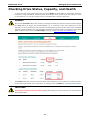
Checking Drive Status, Capacity, and Health
To see an overview of the system’s drive stats, click on the DISK tab. On this page you may monitor the status,
temperature, usage information, and total capacity of the storage drives, as well as get a full S.M.A.R.T. report
on drive behavior. You may also perform low-level formatting and scanning of the drives.
WARNING
Only use the Scan Disk feature after carefully reviewing the manual page and the relevant command options.
The Scan button will trigger the command #fsck –p –f across the entire drive architecture. If used
improperly, or at the wrong time, this could seriously damage the logical file system and result in permanent
data loss. In RAID architectures it could potentially erase data or break the RAID. For a detailed overview of the
fsck command, refer to the Linux fsck.ext4(8) man page, at http://linux.die.net/man/8/fsck.ext4.
The Format button will reformat your drives with a clean ext4 file tree. How the file tree is written across the
physical drives will depend on the architecture you configure under the RAID tab, Creating a Disk Volume.
IMPORTANT!
Formatting your drives will erase all data. Before reformatting your drives, make sure you have backed up
any important data.
7-2
RNAS-1200 Series
Managing Drives and Storage
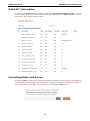
S.M.A.R.T Information
By clicking on the S.M.A.R.T. column header (located in the Physical Drive Information table) users can
access a detailed report of hard drive hardware statistics and health. Select either Disk 1 or Disk 2 to view the
specific drive. When finished, close the window.
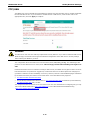
Formatting Disks and Arrays
By clicking Format, the selected drive will be automatically reformatted. Please note that all the data on
the disk will be erased and will not be recoverable. A warning box will appear reminding you of this. If you
wish to format the disk, click OK, or (if you’re having second thoughts), Cancel to quit.
7-3
RNAS-1200 Series
Managing Drives and Storage
Scanning Disks and Arrays
Activating the Scan utility will unmount the drives and initiate a file tree scan of the entire file system by calling
the fsck command. Fsck will be run using the prune (i.e., auto-repair) and force flags; these will
automatically repair the file system (-p) and force (-f) a file system check even if the file tree appears clean.
Please note that scanning the disk may cause some unrecoverable data loss. Click OK if you wish to
scan the disk, or Cancel to quit.
ATTENTION
It is not always advisable to use the fsck utility, and when used improperly the command may irreversibly
damage your system. Read up on proper fsck usage before putting it to use.
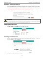
Viewing Disk Volumes
Click Disk Volumes from the DISK tab to view the disk volume stats.
Creating a Disk Volume
This is the section of the RNAS setup interface where you may configure a RAID architecture. To access the
page, select RAID from within the DISK tab.
The following four RAID architectures are available:
7-4
RNAS-1200 Series
Managing Drives and Storage
JBOD
JBOD stands for "Just a Bunch Of Drives". In this configuration, each memory drive is treated as an
independent volume, with no collective properties of any kind. JBOD configurations offer standard performance
with a standard failure rate and normal data security.
Big
The BIG configuration is also called SPANNING. Both disks are concatenated together as if they were one single
drive, or one very large logical volume. BIG is different from RAID 0 because there is no striping of data
involved: each drive handles data at the file level, without any write or read sharing between devices. BIG
configurations have no data redundancy, offer no increase in performance, and have a failure rate double that
of JBOD. Alongside RAID 0, BIG/SPANNING configurations are significantly less reliable and secure than other
configurations.
RAID 0
This configuration stripes data across two physical disks as if they were a single, larger disk. Because both disks
operate as one, the read-write heads are doubled, providing much faster read-write times. However, there is
no data redundancy, so if one drive fails all data across both disks will be lost, simultaneously. This effectively
doubles the configuration's failure rate. RAID 0 provides a moderately increased read-write performance at a
significant cost to reliability and security.
RAID 1
For the RAID 1 configuration, all data is fully duplicated, with one drive mirroring and journaling all data
recorded to the other drive. This provides full data backup at half the failure rate of a normal drive, but at the
cost of reducing the total capacity of the raid to that of a single drive. RAID 1 is among the most secure forms
of memory storage available.
In addition, for RAID 1 you may enable Fast Synchronizations. This is a recommended feature that is only
meaningful in RAID 1 architectures. Fast synchronizations will come at a very slight cost to overall access
speeds, a speed cost that in nearly all cases is negligible. Click Apply to implement. To read more about Moxa’s
fast synchronization technology, see Chapter 10, Enabling Fast Synchronizations.
7-5
RNAS-1200 Series
Managing Drives and Storage
ATTENTION
If you want to replace 1 HDD from the RNAS when RAID 1 is configured, the RNAS will continue to work only
when a new HDD is inserted.
Enabling Disk Encryption
Data encryption at the drive level may only be enabled when configuring your drive architecture.
In addition, for a slight reduction in system access speeds you may enable disk encryption. This utility will use
the 128 bit AES cipher and a unique, randomly generated key to transparently encrypt all data stored on your
drive. Encrypting the drive in this way will mean that only the local RNAS-1200 system will be able to read the
data from the drive.
When finished, click Apply to reformat your drives using your preferred RAID architecture. When building a
drive array (or JBOD), the drives will be automatically reformatted with an ext4 file system. There will be no
need to reformat the drives.
IMPORTANT!
Changing the drive architecture will erase all data. Be sure to backup any important information before
restructuring your drives.
7-6
8
8.
SAMBA: Managing Users and Directories
The following topics are covered in this chapter:
SAMBA
Adding Users
User Accounts Management
Deleting Users
Creating Directories
Editing and Deleting Directories
RNAS-1200 Series
SAMBA: Managing Users and Directories
SAMBA
Samba is a FOSS implementation of Microsoft’s SMB/CIFS networking protocol. Samba provides file and print
services for Microsoft clients, allowing Unix and Linux systems to integrate with a Windows Server Domain or
Active Directory domain as either a member or controller.
The Samba overview page is accessed by clicking on the SAMBA tab in the top ribbon. This page allows
administrators to review the RNAS-1200’s user accounts and shared directories.
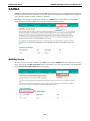
Adding Users
To create new user accounts, navigate to the Users page using the SAMBA tab in the ribbon at the top of the
page. Then click on the Add a New User button. This will take you to the user information and configuration
page, User Quotas and Permissions (see next page).
8-2
RNAS-1200 Series
SAMBA: Managing Users and Directories
User Quotas and Permissions
You may configure new user accounts on this page.
User Name: Provide the login name for the new account.
Quota: Set a storage limit for the new user. The storage quota is a percentage of the total file system capacity,
and is not applied on a per-directory basis. Check No Limit if you do not want to set a quota for this account.
Please note that the quota option is not available under JBOD status.
Description: Here, administrators may enter a short description of the account, to aid in management.
Password: To set a password for the user account, enter the password into the top box and then confirm it
password by entering it again in the lower box. If you do not want to set a password for this user, uncheck the
Set password toggle.
User Permissions, by Directory
This table allows you to configure directory permissions for each user. Three options are available: Read Only,
Read/Write, and Deny Access.
When finished, click Apply to complete the configuration.
ATTENTION
Any directory permissions that are changed in the User Quotas and Permissions page will be applied system
wide. This means that any permissions that have been previously configured via the Directory Labels and
Permissions page will be overwritten with the new values.
8-3
RNAS-1200 Series
SAMBA: Managing Users and Directories
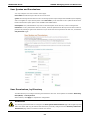
User Accounts Management
If you wish to make modifications to existing user accounts, click on the pencil icon next to the account’s user
name, in the Edit column.
The user’s information may be modified on the User Quotas and Permissions page.
8-4
RNAS-1200 Series
SAMBA: Managing Users and Directories
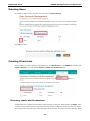
Deleting Users
If you wish to delete a user, check the user name and click Delete User(s).
Click OK to confirm.
Creating Directories
If you would like to create a directory on the RNAS-1200, click Directories from the SAMBA tab, and then click
Create a Directory. This will open the Directory Labels and Permissions page.
Directory Labels and Permissions
Administrators may configure directory labels and permissions on this page. When finished, click Apply. When
creating a directory there are three main parameters that must be configured: the directory name (by which it
will be represented in the file tree), a short description of the directory, and which volume the directory will be
8-5
RNAS-1200 Series
SAMBA: Managing Users and Directories
written to. Because RAID 0, RAID 1, and BIG architectures are built as only a single logical volume, the Disk
Volume drop down will only be meaningful in JBOD configurations.
In the Directory Permissions, by User table users may configure permissions for the newly created directory
according to user accounts.
ATTENTION
Permissions that are changed in the Directory Labels and Permissions page will be applied system wide.
This means that any permissions that have been configured using the User Quotas and Permissions page
will be overridden by the new values.
In addition, if you want to use DataXPro, you have to enable it before you create a shared network folder.
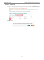
Editing and Deleting Directories
If you wish to edit directory labels and permissions for an existing directory, return to the Directory Creation
and Management page by clicking on Directories under the SAMBA tab in the main menu ribbon.
8-6
RNAS-1200 Series
SAMBA: Managing Users and Directories
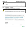
Deleting Directories
If you want to delete a directory, check the box next to the directory name and then click Delete Directory(s).
Click OK to confirm
.
8-7
9
9.
Vibration and Temperature Protections
The following topics are covered in this chapter:
Configuring Data XPro™
Vibration Protection
High Temperature Protection
RNAS-1200 Series
Vibration and Temperature Protections
Configuring Data XPro™
Data XPro™ is a patented, innovative technology that helps protect your data from harsh vibration and high
temperature. Click the DATA XPRO tab from the main menu to navigate to the configuration page.
Vibration Protection
You may Enable Data XPro™ vibration protections by selecting the appropriate toggle in the Vibration
Protection section of this page. Next, a vibration threshold must be selected from the drop-down menu. When
vibration levels exceed the configured threshold, new data writes will be temporarily stored in a solid state data
buffer. Once the vibration stops, any data modifications will be applied to the hard disk.
Please consult the manufacturer’s website for the technical specifications regarding vibration thresholds for
your hard drives.
Please note that vibration protection is not available under JBOD architectures.
When finished, click Apply. You need to reboot the RNAS-1200 to activate the configuration. Click OK to
reboot.
9-2
RNAS-1200 Series
Vibration and Temperature Protections
ATTENTION
1. For a 500GB HDD, it will take about 5 minutes to complete the process to enable DataXPro vibration
protection.
2. The data on the disk volume will be formatted after configuring DataXPro. We strongly recommend you
backup your data before configuring DataXPro.
High Temperature Protection
Select Enable to configure the temperature thresholds for protection against heat.
ATTENTION
Be aware that when the system reaches the configured heat threshold all drive activity will stop, and will not
recommence until the total system temperature decreases to levels lower than the configured threshold.
During this time, no data will be stored in the buffer and your NAS system will effectively shut down.
9-3
10
10.
Enabling Fast Synchronizations for RAID 1
The following topics are covered in this chapter:
Enabling Fast Synchronizations
RNAS-1200 Series
Enabling Fast Synchronizations for RAID 1
Enabling Fast Synchronizations
The RNAS-1200 features Fast Synchronizations for its RAID 1 architecture. While this comes at a small cost
to regular access times, when this feature is enabled the file system will store the position of the last successful
write and, in the event of unexpected system crashes, begin resynchronization of the drives from that position.
This means that unexpected system crashes will no longer cripple your RAID with laborious, hours-long
resynchronization processes. When data inconsistencies occur, fast synchronizations will be able to
synchronize a two disk array in only seconds, or two or three short minutes at the very most. Please note that
fast synchronizations are only meaningful in RAID 1 architectures.
ATTENTION
To enable fast synchronizations, you must toggle the Fast Synchronization box when you are configuring
your RAID 1 array.
10-2
11
11.
The following topics are covered in this chapter:
Setting Up IHS
Hardware Version 1.1 IHS Settings
Enabling IHS™
RNAS-1200 Series
Enabling IHS™
Setting Up IHS
The RNAS-1200 offers an Intelligent Heating Solution™ (IHS) to ensure the system will work reliably even in
extremely low temperatures. IHS is an automated, onboard heating system that will heat a hard disk or solid
state storage drive to a preset temperature. If the RNAS-1200 is booted up and the system senses the
environmental temperature has dropped to below freezing (zero degrees Celsius / 32 degrees Fahrenheit), the
RNAS-1200 may heat the system to either -25°C (TX mode) or 0°C (T1 mode), depending on how the utility is
configured.
The system ships with IHS TX mode already enabled. To function properly, IHS requires storage drives
specifically designed for harsh environmental conditions. In industry literature these types of drives are often
called “automotive grade.” Below is a list of drives which are currently (Oct. 2012) approved for use on the
RNAS-1200 system. This list will be continuously updated as Moxa’s technical support teams verify new drives
for approved use, so to find the most recent list of approved drives you may visit the Moxa RNAS support
documentation pages, or attempt to download the file directly from this link.
Industrial-Grade Hard Disk Drives Approved for IHS TX Mode (Oct. 2012)
Manufacturer
Capacity
Model Name
Hitachi (Endurastar)
100GB
HEJ421010G9SA00
Toshiba (MKxx60GSC)
100GB
MK1060GSC
Industrial-Grade Hard Disk Drives Approved for IHS T1 Mode (Oct. 2012)
Manufacturer
Capacity
Model Name
Hitachi
100GB
HEJ421010G9SA00
Toshiba
100GB
MK1060GSC
WD
500GB
WD5000LPVT
WD
500GB
WD5000BUCT
Seagate
500GB
ST9500325AS
The IHS TX mode is for the most severe cold weather environments. This requires a specially manufactured
industrial-grade storage drive (such as some of the Hitachi Endurastar or Toshiba MKxx60GSC products)
designed for environmental extremes. When configured for TX mode, upon detecting external temperatures
that is less than -25°C the RNAS-1200 will, over the course of 20 minutes, heat the system to -25°C and then
automatically boot up the system.
The design requirements for IHS T1 mode are not so severe as those for TX mode. When configured for T1
mode, upon detecting external temperatures that is less than 0°C the RNAS-1200 will, over the course of 45
minutes, heat the system to 0°C and then automatically boot the system.
To set up the RNAS-1200 for IHS T1 or TX mode (or to disable IHS), you will need to access the RNAS PCB to
set the onboard jumpers. The steps below describe how to configure the onboard IHS jumpers.
Step 1: Remove the screws and the top cover of the RNAS-1200. To review how this is done, please refer to
the manual section Installing the Storage Drive.
Step 2: Remove the hard disk on the right side to expose the location of jumper J16. Please see the photo at
the top of the next page for a detailed picture of where the J16 jumper series is located.
ATTENTION
Please note that for the RNAS-1201 and RNAS-1211 models TX mode is the system default. Unless you
have installed suitably engineered hard disks, you will need to switch the system to either disable IHS or switch
it to T1 mode. Using TX mode with commercial grade hard drives in cold weather may result in severe and
irreversible damage to your storage drives.
11-2
RNAS-1200 Series
Enabling IHS™
Step 3: To switch the IHS mode, adjust the jumpers to one of the configurations shown below.
TX Mode (-40 to -25°C):
System Default
This mode is for the most extreme
environments, and requires the most
rugged drive hardware. Over the course of
20 minutes, TX mode heats the drive to
-25°C and then automatically powers up
the system.
T1 Mode (-25 to 0°C)
T1 is for environments that often fall below
freezing, but do not go below 25°C; it also
requires industrial-grade drive hardware.
Over 45 minutes T1 mode will heat the
HDD to 0°C and then power on the system
.
Disabled:
To entirely disable IHS, remove all jumper
covers. This will completely turn off the
heating system so that no automated
heating processes will be active.
Step 4: Replace and secure the hard disks and chassis to complete the IHS configuration.
11-3
RNAS-1200 Series
Enabling IHS™
Hardware Version 1.1 IHS Settings
For the RNAS-1200 with hardware version 1.1, the IHS can be configured via the web browser, without
adjusting the jumper. Follow these steps for the configuration.
1. Check the label on the rear panel of the RNAS-1200, and make sure the version is 1.1.
2. Select IHS in SYSTEM tab in the web browser.
11-4
RNAS-1200 Series
Enabling IHS™
3. Select the mode you want to use, then click Apply to take effect.
11-5
12
12.
Setting Up Network Shares
The following topics are covered in this chapter:
Building a Network Share on Windows Systems
Method 1: Manual Login
Method 2: Building a Permanently Mapped Share
Deleting a Permanently Mapped Share
Building a Network Share on Linux Systems
Connecting to the RNAS-1200 SAMBA Server
Deleting a Mapped Folder on Ubuntu Linux
RNAS-1200 Series
Setting Up Network Shares
Building a Network Share on Windows Systems
To build a Windows network share from a client computer to the RNAS-1200 users may use one of two methods.
The first is a manual login; each time you connect you will need to type the RNAS-1200’s network IP address,
username, and password, and connections will be subject to timing out.
The second method is to build a permanent shared folder link on your computer desktop. The advantage of this
is that your computer will have a transparent link to the shared directory that will allow you to access it as if it
were merely another directory on your local hard drive. However, if the networking information changes or if
you wish to connect to a second RNAS you will likely need to purge your computer of the permanent settings.
Method 1: Manual Login
Step1: Type the network IP address into the address field of the Windows Explorer file manager and press
Enter. Your computer should now automatically connect to the RNAS-1200’s SAMBA server.
Step2: Once the file manager is connected to the SAMBA server, Windows will ask you for a user name and
password. At this point you should enter the username associated with the SAMBA account you configured in
Chapter 8, SAMBA: Managing Users and Directories. Unless you have already configured directories to be
available for user shares, there will be no way to continue the configuration.
Step 3: After successfully logging on to the RNAS-1200 SAMBA server, you should see any existing directories
that SAMBA has been configured to share. Click on the directory icon to read or write files. Please note that
read and write permissions are subject to any server-side limitations that may have been configured in Chapter
8, SAMBA: Managing Users and Directories.
12-2
RNAS-1200 Series
Setting Up Network Shares
ATTENTION
The username and password associated with the SAMBA account should not be the same password and user
account associated with the RNAS administration interface, or with its administrative account.
Method 2: Building a Permanently Mapped Share
If you do not want to force users to manually connect to the RNAS-1200 each time they log on, you may create
a shared directory on the Windows desktop using the automated Map Network Drive utility.
Step1: After manually logging in to SAMBA using method 1, right-click on the shared directory icon and
choose Map Network Drive. You will again be prompted for the username and password.
Step2: Specify your preferred drive letter by which the connection will be identified. Click Finish.
12-3
RNAS-1200 Series
Setting Up Network Shares
Step 3: A new network drive will now appear on your computer. From now on, you will only need to
double-click the drive to connect to the RNAS-1200. If you wish to create a shortcut to your desktop, you may
do so by right-clicking and selecting Create Shortcut.
Deleting a Permanently Mapped Share
Sometimes, you may need to connect to the RNAS-1200 SAMBA server by a different user account. When this
happens, you will need to delete the permanently mapped share. To do this, navigate to the My Computer
window and right-click on the network drive. From there, select Disconnect.
Alternately, you may delete the configuration using the console command C:\...>net use \\IP address
/delete, as shown below.
C:\Documents and Settings\Administrator> net use \\192.168.27.231 \delete
\\192.168.27.231 was deleted successfully
If you have forgotten the RNAS-1200’s IP address, just use the command net use:
C:\Documents and Settings\Administrator> net use
New connections will be remembered.
Status
Local
Remote
Network
----------------------------------------------------------------------------OK
\\192.168.27.231
The command completed successfully
12-4
Microsoft Windows Network
RNAS-1200 Series
Setting Up Network Shares
Building a Network Share on Linux Systems
Connecting to the RNAS-1200 SAMBA Server
If you are using the Linux Ubuntu GUI, you will only be able to access the RNAS-1200 SAMBA server after first
installing the smbfs package. You may use the Synaptic software manager, or #:/apt-get smbfs. After
installing the appropriate software, simply follow these steps:
Step 1: Open the Home Folder window, in the Places menu. Then press Ctrl + L to display the Go To table.
Step 2: Enter smb://IP address to connect the RNAS-1200.
Step 3: You should now be able to see the shared directory.
12-5
RNAS-1200 Series
Setting Up Network Shares
Step 4: Click on the shared directory icon and a dialog should appear. Here you may enter the user name and
password for the SAMBA share you wish to access. You may also need to configure a workgroup name. The
default workgroup name for both Ubuntu and the RNAS-1200 SAMBA server is the same as the Windows
default workgroup name: WORKGROUP. Type this into the Domain field, then click Connect.
Step 5: You should now be able to access the SAMBA share locally, from your computer, as a
network-extended directory.
To do this from the Linux Console, you may follow these steps:
Step 1: First, install the SAMBA file system software.
root@~#:apt-get smbfs
Step 2: Mount the Samba share directory using the following commands:
smbmount //IP address/DIRECTORY_NAME /LOCAL_DIRECTORY \
–o username=USER_NAME,password=PASSWORD
root@~#:smbmount //IP address/DIRECTORY_NAME /LOCAL_DIRECTORY \
–o username=USER_NAME,password=PASSWORD
12-6
RNAS-1200 Series
Setting Up Network Shares
Deleting a Mapped Folder on Ubuntu Linux
If you are using Linux Ubuntu, see this step:
Right-click the DIRECTORY_NAME on IP addrerss in Network list, and then select umount to disconnect.
If you are comfortable using the Linux Console, you may use the umount command to unmount a shared
Samba directory.
12-7