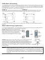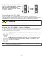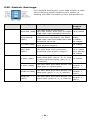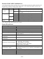
1
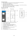
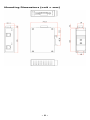
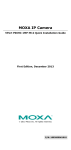
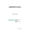
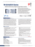
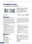
Moxa High-Power PoE+ Injector INJ-24A Series Hardware Installation Guide First Edition, October 2012 2012 Moxa Inc. All rights reserved. P/N: 1802000240020 Overview The Moxa INJ-24A Series high-power PoE+injector is a 1-port PoE+ injector that delivers both data and electrical power to Ethernet-enabled devices using a single Ethernet cable. The INJ-24A can supply up to 36 watts of power in 2-pair mode or 60 watts in 4-pair mode through the Ethernet port, and can power IEEE 802.3af/at compliant powered devices (PD), such as wireless access points or IP cameras, eliminating the need for additional wiring. The INJ-24A supports Gigabit communication, which is vital for high-speed and low-latency applications. The INJ-24A also offers a wide operating temperature range of -40 to 75°C, and is designed to withstand a high degree of vibration and shock. An innovative hardware design enhances the INJ-24A with flexible options of Mode A and Mode B PoE powering modes. This makes the INJ-24A perfect for outdoor field installation of M12-connector wireless APs and IP cameras which only have 4 pins in the cable. In addition, the INJ-24A can resist 3KV surges from the PoE port, protecting system operations in critical industrial environments, and complies with CE/FCC and UL standards for safety. Wiring Requirements WARNING Do not disconnect modules or wires unless the power supply has been switched off or the area is known to be non-hazardous. The devices may only be connected to the supply voltage shown on the type plate. The devices are designed for operation with a Safety Extra-Low Voltage. Thus, they may only be connected to the supply voltage connections and to the signal contact with the Safety Extra-Low Voltages (SELV) in compliance with IEC 60950-1/EN 60950-1. WARNING The power for this product is intended to be supplied by a Listed Power Unit, with output marked LPS, and rated to deliver 24 DC at a maximum of 3.72 A. WARNING This unit is a built-in type. When the unit is installed in another piece of equipment, the equipment enclosing the unit must comply with fire enclosure regulation IEC 60950-1/EN60950-1 (or similar regulation). -2- WARNING Safety First! Be sure to disconnect the power cord before installing and/or wiring your Moxa PoE injector. Calculate the maximum possible current in each power wire and common wire. Observe all electrical codes dictating the maximum current allowable for each wire size. If the current goes above the maximum ratings, the wiring could overheat, causing serious damage to your equipment. You should also pay attention to the following items: • • • • • Use separate paths to route wiring for power and devices. If power wiring and device wiring paths must cross, make sure the wires are perpendicular at the intersection point. NOTE: Do not run signal or communications wiring and power wiring in the same wire conduit. To avoid interference, wires with different signal characteristics should be routed separately. You can use the type of signal transmitted through a wire to determine which wires should be kept separate. The rule of thumb is that wiring that shares similar electrical characteristics can be bundled together. Keep input wiring and output wiring separated. It is strongly advised that you label wiring to all devices in the system when necessary. Package Checklist The Moxa INJ-24A Series is shipped with the following items. If any of these items is missing or damaged, contact a Moxa customer service representative for assistance. • • • Moxa INJ-24A High-Power PoE+ Injector Hardware Installation Guide Moxa Product Warranty Statement Features High Performance Technology • • • 10/100/1000BaseT(X) Provides up to 36 watts (2-pair mode) or 60 watts (4-pair mode) per PoE port Built-in 24/48 VDC booster for PoE and PoE+ Innovative Easy Installation • • Selectable PoE Mode A and Mode B connection options SmartPoE LED indication -3- Rugged Design • • • • • • • Active PoE short-circuit and current-overloading protections Auto PoE device detection and classification 3 KV PoE surge resistance Redundant dual power inputs Operating temperature range from 0 to 60°C, or extended operating temperature from -40 to 75°C for “T” models IP30, rugged high-strength case DIN-Rail or panel mounting ability Panel Layout 1. 2. 3. 4. 5. 6. 7. 8. 9. 10. 11. 12. 13. Terminal block for P1/P2 power inputs Power input P1 LED Power input P2 LED 10/100/1000BaseT(X) data port SmartPoE LED indicator (PoE status) PoE power output mode LED 10/100/1000BaseT(X) PoE output port Model name Grounding screw Screw hole for wall mounting kit DIN rail mounting kit DIP switches Terminal block for P1/P2 power inputs -4- Mounting Dimensions (unit = mm) -5- DIN-Rail Mounting The DIN rail attachment plate should already be fixed to the back panel of INJ-24A when you take it out of the box. If you need to reattach the DIN Rail attachment plate, make sure the stiff metal spring is situated towards the top, as shown in the figures below. STEP 1: STEP 2: Insert the top of the DIN rail into theThe DIN rail attachment unit will slot just below the stiff metal spring.snap into place as shown below. To remove the INJ-24A from the DIN rail, simply reverse steps 1 and 2 above Wall Mounting (optional) For some applications, you will find it convenient to mount the INJ-24A on the wall, as shown in the following figures. STEP 1: Remove the aluminum DIN rail attachment plate from the INJ-24A’s rear panel, and then attach the wall mount plates as shown in the diagram to the right. STEP 2: Mounting the INJ-24A on the wall requires 4 screws. Use the switch, with wall mount plates attached, as a guide to mark the correct locations of the 4 screws. The heads of the screws should be less than 6.0 mm in diameter, and the shafts should be less than 3.5 mm in diameter, as shown in the figure at the right. NOTE Before tightening the screws into the wall, make sure the screw head and shank size are suitable by inserting the screw into one of the keyhole-shaped apertures of the wall mounting plates. Do not tighten the screws completely—leave about 2 mm to allow room for sliding the wall mount panel between the wall and the screws. -6- STEP 3: Once the screws are fixed on the wall, insert the four screw heads through the large parts of the keyhole-shaped apertures, and then slide the EDS downwards, as indicated. Tighten the four screws for added stability. Grounding the INJ-24A Grounding and wire routing help limit the effects of noise due to electromagnetic interference (EMI). Run the ground connection from the ground screw to the grounding surface prior to connecting devices. ATTENTION This product is intended to be mounted to a well-grounded mounting surface, such as a metal panel. Wiring the INJ-24A’s Power Outputs The 4-contact terminal block connector on the INJ-24A’s top panel is used for dual 24/48 VDC power inputs. Top and front views of the terminal block connectors are shown here. STEP 1: Insert the negative/positive DC wires into the V-/V+ terminals. STEP 2: To keep the DC wires from pulling loose, use a small flat-blade screwdriver to tighten the wire-clamp screws on the front of the terminal block connector. STEP 3: Insert the plastic terminal block connector prongs into the terminal block receptor, which is located on the INJ-24A’s top panel. NOTE Both V1+ and V2+ are internally connected. Incorrect cabling may cause device damage. -7- DIP Switch Settings The default setting for each DIP switch is OFF. The following table explains the effect of setting the DIP switches to the ON positions. DIP Switch Setting 1 The INJ-24A is forced to 802.3af (ON) 802.3af mode and only accepts IEEE 802.3af standard devices. The INJ-24A automatically 802.3af/at detects the standard, for both (OFF) IEEE 802.3af and IEEE 802.3at standard devices. The INJ-24A is set to support Hi PWR (ON) high power output. 2 Std. PoE (OFF) 3 Description The INJ-24A only provides standard PoE power output. 15.4 watts Std PoE: 30 watts Hi PWR: 36 watts 36 watts 802.3af: 15.4 watts 802.3af/at: 30 watts The INJ-24A provides power via both data pair (pin 1, 2, 3, and 60 watts 6) and phantom pair (pin 4, 5, 7, and 8). See DIP The INJ-24A provides power via Switch 1 2-pair (OFF) data pair or spare pair. and 2 See DIP The INJ-24A provides power via Mode A (ON) Switch 1 data pair (pins 1, 2, 3, and 6). and 2 See DIP Mode B The INJ-24A provides power via Switch 1 (OFF) spare pair (pins 4, 5, 7, and 8). and 2 4-pair (ON) 4 Max Output Power -8- Smart PoE LED Indicators Two SmartPoE LEDs indicate the current status between PSE and PD and the power output mode of the INJ-24A. The following table shows the details about these SmartPoE LEDs. LED Color State Description Power is being supplied to power input P1 ON /P2 P1, P2 Amber Power is not being supplied to power input OFF P1 / P2 802.3af/at Green ON 802.3at connection (SmartPoE) Blinking PoE current overloading OFF No PoE power output ON 802.3af connection Amber Blinking PoE current overloading OFF No PoE power output ON 4-pair mode PoE power output 4-pair Green mode OFF 2-pair mode PoE power output Note: If INJ-24A is in 4-pair mode but with a 2-pair mode PD, the 802.3af/at LED will always be green. Specifications Technology Standards Interface RJ45 Ports LED Indicators Power Input Voltage Input Current Connection Overload Current Protection Reverse Polarity Protection PoE Port IEEE 802.3, 802.3u, 802.3ab, 802.3af, 802.3at 10/100/1000BaseT(X) speed P1, P2, 802.3af/at, 4-pair mode 24/48 VDC (21.6 to 57 VDC) Max. 3.72 A @ 24 VDC (in 4-pair maximum output state) Removable 4-contact terminal block 5A Present Standard mode: 802.3af: 15.4 watts 802.3af/at: 30 watts Maximum Power Output High-power mode: 36 watts 4-pair mode: 60 watts Surge Resistance 3 KV Mode A (power on pins 1, 2, 3, and 6) and Mode Connection Type B (power on pins 4, 5,7, and 8) selectable by DIP switch Mechanical Housing IP30 protection, plastic case Dimensions 115 × 30.3 × 78.8 mm (H x W x D) Weight 245 g Installation DIN-Rail, wall mounting -9- Environmental Limits Operating Temperature Standard Models: 0 to 60°C (32 to 140°F) Wide Temp. Models: -40 to 75°C (-40 to 167°F) Storage Temperature -40 to 85°C (-40 to 185°F) Ambient Relative 5 to 95% (non-condensing) Humidity Regulatory Approvals EMI FCC Part 15, CISPR (EN 55022) class A EMS EN 61000-4-2 (ESD), Level 3 EN 61000-4-3 (RS), Level 3 EN 61000-4-4 (EFT), Level 3 EN 61000-4-5 (Surge), Level 3 EN 61000-4-6 (CS), Level 3 EN 61000-4-8, Level 5 Shock IEC 60068-2-27 Freefall IEC 60068-2-32 Vibration IEC 60068-2-6 Warranty Time Period 5 years Details www.moxa.com/warranty Technical Support Contact Information www.moxa.com/support Moxa Americas: Toll-free: 1-888-669-2872 Tel: 1-714-528-6777 Fax: 1-714-528-6778 Moxa China (Shanghai office): Toll-free: 800-820-5036 Tel: +86-21-5258-9955 Fax: +86-21-5258-5505 Moxa Europe: Tel: +49-89-3 70 03 99-0 Fax: +49-89-3 70 03 99-99 Moxa Asia-Pacific: Tel: +886-2-8919-1230 Fax: +886-2-8919-1231 - 10 -