1
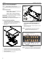
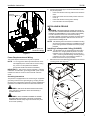
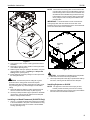
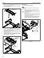
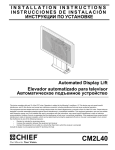
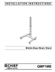
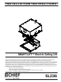
INSTALLATION INSTRUCTIONS
Instrucciones de instalación
Installationsanleitung
Instruções de Instalação
Istruzioni di installazione
Installatie-instructies
Instructions d´installation
SMART-LIFT™ Electric Ceiling Lift
This device complies with part 15 of the FCC rules. Operation is subject to the following 2 conditions: (1) This device may not cause harmful
interference, and (2) this device must accept any interference received, including interference that may cause undesired operation.
This equipment has been tested and found to comply with the limits of a Class B digital device, pursuant to Part 15 of the FCC rules. These limits are
designed to provide reasonable protection against harmful interference in a residential installation. This equipment generates, uses and can radiate
radio frequency energy, and if not installed and used in accordance with the instructions, may cause harmful interference to radio or television
communications. However, there is no guarantee that the interference will not occur in a particular installation. If this equipment does cause harmful
interference to radio or television reception, which can be determined by turning the equipment off and on, the user is encouraged to try to correct
the interference by one of the following measures:
•
Reorient or relocate the receiving antenna
•
Increase the separation between the equipment and receiver
•
Connect the equipment to an outlet on a circuit other than that to which the receiver is connected
Consult the dealer or and experienced radio/TV technician for help
SL236i
SL236i
Installation Instructions
DISCLAIMER
Milestone AV Technologies, and its affiliated corporations and
subsidiaries (collectively, "Milestone"), intend to make this
manual accurate and complete. However, Milestone makes no
claim that the information contained herein covers all details,
conditions or variations, nor does it provide for every possible
contingency in connection with the installation or use of this
product. The information contained in this document is subject
to change without notice or obligation of any kind. Milestone
makes no representation of warranty, expressed or implied,
regarding the information contained herein. Milestone assumes
no responsibility for accuracy, completeness or sufficiency of
the information contained in this document.
WARNING: TO REDUCE THE RISK OF
BURNS, FIRE, ELECTRIC SHOCK, OR INJURY TO
PERSONS:
•
•
•
Chief® is a registered trademark of Milestone AV Technologies.
All rights reserved.
•
•
IMPORTANT SAFETY INSTRUCTIONS
•
•
•
•
WARNING alerts you to the possibility of
serious injury or death if you do not follow the instructions.
Always turn off power at source before putting on or
taking off parts.
Use this mounting system only for its intended use as
described in these instructions. Do NOT use
attachments not recommended by the manufacturer.
Never operate this mounting system if it has a
damaged test cord or test plug. If it is not working
properly during testing, return the mounting system to
a service center for examination and repair.
Keep the test power cord away from heated surfaces.
Never operate the mounting system with the air
openings blocked. Keep the air openings free of lint,
hair, and the like.
Never drop or insert any object into any opening.
Do not use outdoors unless marked for outdoor use.
Route cords and cables as shown in the installation
instructions.
To disconnect, turn all controls to the off position, then
turn off power at source.
WARNING: RISK OF ELECTRIC SHOCK!
Connect this mounting system to a properly grounded outlet
only. See Grounding Instructions.
CAUTION alerts you to the possibility of
damage or destruction of equipment if you do not follow the
corresponding instructions.
WARNING: FAILURE TO READ AND
FOLLOW THE FOLLOWING INSTRUCTIONS CAN RESULT
IN SERIOUS PERSONAL INJURY, DAMAGE TO EQUIPMENT
OR VOIDING OF FACTORY WARRANTY. It is the installer’s
responsibility to make sure all components are properly
assembled and installed using the instructions provided.
CAUTION: Changes or modifications to this
unit not expressly approved by the manufacturer can void the
units FCC compliance rating and make the unit illegal to
operate.
WARNING: Failure to provide adequate
structural strength for this component can result in serious
personal injury or damage to equipment! It is the installer’s
responsibility to make sure the structure to which this
component is attached can support five times the combined
weight of all equipment. Reinforce the structure as required
before installing the component.
IMPORTANT ! : Model SL236i is suitable for use in Other
Environmental Air Space in Accordance with Section 300.22(C)
of the National Electrical Code.
When using an electrical mounting system, basic precautions
should always be followed, including the following:
READ ALL INSTRUCTIONS BEFORE USING THIS
PRODUCT!!!!
DANGER: TO REDUCE THE RISK OF
WARNING: Exceeding the weight capacity
can result in serious personal injury or damage to equipment! It
is the installer’s responsibility to make sure the weight of all
components attached to the SL236i does not exceed 35 lbs
(15.9 kg).
WARNING: RISK OF INJURY! Do not place
video equipment such as televisions or computer monitors on
the ceiling panel of the SL236. The total weight of any objects
on the ceiling panel must not exceed 5 lbs (2.3 kg).
ELECTRIC SHOCK:
1.
Always turn off power at source before cleaning.
NOTE: This system has no user serviceable parts.
--SAVE THESE INSTRUCTIONS-2
Installation Instructions
SL236i
TOOLS REQUIRED FOR INSTALLATION
PARTS
I/M
A (1)
[Ceiling lift]
(SL236FDi Shown)
J (1)
[Power cord]
x1
B (1)
[Push button assembly]
C (5)
[4" cable tie]
F (5)
[Cable tie
mount]
D (1)
[External terminal
cover plate]
E (1)
[Jumper wire]
G (4)
6-32 x 3/16
H (2)
[Rubber grommet]
3
SL236i
Installation Instructions
LEGEND
Tighten Fastener
Phillips Screwdriver
Apretar elemento de fijación
Destornillador Phillips
Befestigungsteil festziehen
Kreuzschlitzschraubendreher
Apertar fixador
Chave de fendas Phillips
Serrare il fissaggio
Cacciavite a stella
Bevestiging vastdraaien
Kruiskopschroevendraaier
Serrez les fixations
Tournevis à pointe cruciforme
Loosen Fastener
Adjust
Aflojar elemento de fijación
Ajustar
Befestigungsteil lösen
Einstellen
Desapertar fixador
Ajustar
Allentare il fissaggio
Regolare
Bevestiging losdraaien
Afstellen
Desserrez les fixations
Ajuster
TABLE OF CONTENTS
Disclaimer.....................................................2
Installing in a Wood Framework (Joists)........9
Tools Required For Installation......................3
Installing Projector on SL236i........................9
Parts..............................................................3
Adjustments.................................................10
Legend..........................................................4
Routing Cables............................................11
Dimensions................................................... 5
Connecting Control Wiring...........................12
Installation Requirements..............................6
Connecting to Power Supply........................12
Power Requirements.....................................6
Plenum Rated Installation............................12
Pre-test Lift Before Installation.......................6
Wiring Options.............................................12
Power Requirements and Wiring.................. .7
Table 1: Wiring Table...................................13
Grounding Instructions.................................. 7
Table 2: Internal Terminal Descriptions........14
Installing in Ceiling.........................................7
Internal/External Wiring Terminal
Descriptions.....................................15
Installing in Suspended Ceiling (SL236SPi)...7
4
Installation Instructions
SL236i
DIMENSIONS
SL-236FDi
[520.7]
20.50
[260.4]
10.25
[732.8]
28.85
[584.2]
23.00
[698.5]
27.50
MAXIMUM AVAILABLE SPACE FOR
PROJECTOR AND EQUIPMENT
HxWxD = 9.25 x 20.50 x 22.75 INCHES
[235.0 x 520.7 x 577.9mm]
[635.0] 25.00
[669.3]
26.35
[19.1] .75
[280.9]
11.06
.65 [16.5]
1.06 [26.9]
[914.4]
36.00
MAX
[606.3]
23.87
[260.4]
10.25
[76.2]
3.00
[606.3]
23.87
DIMENSIONS: [MILLIMETERS]
INCHES
SL-236SPi
[520.7]
20.50
[110.2]
4.34
[584.2]
23.00
[719.1]
28.31
[700.0]
27.56
MAXIMUM AVAILABLE SPACE FOR
PROJECTOR AND EQUIPMENT
HxWxD = 9.25 x 20.50 x 22.75 INCHES
[235.0 x 520.7 x 577.9mm]
.65 [16.5]
1.06 [26.9]
[638.0]
25.12
[282.4]
[311.2] 11.12
12.25
1.07 [27.2]
.41 [10.4]
[914.4]
36.00
MAX
CURRENT 9.26 [235.2]
MAX 9.91 [251.7]
MIN 7.78 [197.6]
[606.6]
23.88
REMEMBER TO ADD .375” TO 1.00”
[9.5 TO 25.4mm] TO THE MAX
9.91” [251.7mm] OF YOUR PROJECTOR
HEIGHT TO ALLOW FOR THE ROOM THE
SLB BRACKET WILL CONSUME.
[606.6]
23.88
[633.5]
24.94
DIMENSIONS: [MILLIMETERS]
INCHES
5
SL236i
Installation Instructions
INSTALLATION REQUIREMENTS
NOTE: Throughout this document, reference to SL236i refers
External
wiring terminal
to both SL236FDi and SL236SPi models.
The SL236i has been designed to be mounted recessed into a
ceiling.
Electrical
cover
Power Requirements
•
230VAC, 50Hz, 2 amps (if NOT installing an
internal outlet for projector).
•
230VAC, 50Hz, 12 amps (if installing an
internal outlet [not provided] for projector).
5
IMPORTANT ! : An external disconnect switch accessible to
the user must be provided during installation.
IMPORTANT ! : Installation and maintenance of this product
must be completed by a qualified service technician.
Test
cord
4
x2
Pre-Test Lift before Installation
1.
2.
Carefully inspect the SL236i for any shipping damage. If
any damage is apparent, do NOT continue with the
installation. Instead, contact Chief for further instructions.
Attach supports (not provided) to the top of lift.
(See Figure 1)
Figure 2
6.
7.
Supports
Place the jumper wire (E) on the external wiring terminal
contacts labeled 2 and 5, and wire the push button
assembly (B) to contacts 1 (red) and 6 (black). (See
Figure 3).
Plug the SL236i test inlet in using the supplied 6 ft. power
cord (J). (See Figure 2)
NOTE: The supplied power cord (J) may not work in all
countries, and the user may need to supply an
appropriate cord for the country of use.
Place jumper wire (E) (2 and 5)
Wire push button assembly (B) (1-red, 6-black)
Figure 1
Figure 3
NOTE: (See Figure 2) for location of external wiring terminal.
3.
4.
5.
6
Suspend the lift at least 3-1/2 ft. above a surface from a
suitable structure such as saw horses, ladders or tables.
Remove and save two screws holding side electrical cover
in place. (See Figure 2)
Remove electrical cover. (See Figure 2)
(See Figure 4) for location of internal wiring terminal.
Installation Instructions
SL236i
8.
Press the push button (B) to test the SL236i while it is still in
the pre-test position.
•
Press when the lift is at its top position and it will move
down.
•
Press when the lift is at its bottom position and it will
move up.
•
Press while the lift is moving and it will stop.
•
Leave SL236i in the closed position.
Internal
wiring terminal
INSTALLING IN CEILING
WARNING: IMPROPER INSTALLATION CAN LEAD TO
LIFT FALLING CAUSING SEVERE PERSONAL INJURY OR
DAMAGE TO EQUIPMENT! It is the installers responsibility
to make certain the structure to which the lift is being
mounted is capable of supporting five times the weight of the
lift and all attached equipment. Reinforce the structure as
required before installing the lift.
NOTE: The following instructions assume a suitable mounting
structure and surface exists prior to installation and all
power and signal wires and cables have been properly
installed.
[Some parts not
shown for clarity]
Installing in a Suspended Ceiling (SL236SPi)
NOTE: The SL236SPi may be suspended from three 3/8 in.
diameter x 8 in. length (minimum) Grade 2 or better
threaded rods (not provided) which are secured to a
1-5/8" x 1-5/8" 12 ga metal framing channel (spanning
a maximum of 5 feet--not provided) by Grade 2 or
better 3/8" channel nuts (not provided).
Remove and save nuts attaching guide wires to two corners
of ceiling panel. (See Figure 5)
Figure 4
Power Requirements and Wiring
The SL236i requires 230VAC 50 Hz power to operate.
1.
NOTE: A 6 ft. long power cable is provided with the mount.
This supplied power cord should be used for testing
only, and not for the permanent installation.
(The SL236i will be hard-wired at installation.)
IMPORTANT ! : This product must be grounded. If it should
malfunction or break down, grounding provides a path of least
resistance for electric current to reduce the risk of electric
shock.
2
Ceiling
Panel
Grounding Instructions
This product is equipped with a test cord having an equipmentgrounding conductor and a grounding plug. The plug must be
plugged into an appropriate outlet that is properly installed and
grounded in accordance with all local codes and ordinances.
1
x2
WARNING: RISK OF ELECTROCUTION! All electrical
wiring required for installation should be installed by a
qualified electrician.
WARNING: PINCH HAZARD! FINGERS OR HANDS
BETWEEN MOVING PARTS CAN LEAD TO SEVERE
PERSONAL INJURY! Keep fingers and hands away from
mount when operating.
2
Remove
clip from
hole
Guide
wire
Clip
Figure 5
7
SL236i
2.
3.
4.
5.
6.
Installation Instructions
Pull down on each corner of ceiling panel to remove ceiling
panel clips from rectangular holes. (See Figure 5)
Install the SMA651 (optional accessory) at this time, if
applicable, following instructions included with the kit.
Cut the ceiling grid to fit the perimeter of the SL236SPi.
Place SL236SPi onto threaded rods, inserting the rods into
the three slots on top of the SL236SPi housing.
(See Figure 6)
Secure the threaded rods to the SL236SPi with Grade 2 or
better 3/8 in. jam nuts (not provided) and washers (one of
each on inside and one of each on outside--not provided).
Side
Channel
(Top view of SL236i)
Insert rods
into 3 slots
Figure 7
CAUTION: The lift MUST be installed square and parallel.
Avoid stressing or bending the lift during installation.
9.
Figure 6
Install the SMA-620 (optional accessory) to the SL236SPi,
if applicable, following instructions included with the kit.
8. Insert the ceiling grid edge surrounding the SL236SPi into
the side channel of the SL236SPi. (See Figure 7)
NOTE: The side channel of the lift will support the weight of
the grid and ceiling tiles.
Use the provided push button (B) to operate the SL236SPi
up and down, ensuring that all clearances are adequate.
10. Replace surrounding ceiling tile.
11. Remove four screws and the ceiling tile retainer from the
ceiling panel. (See Figure 8)
7.
Ceiling
Panel
Ceiling
Tile
Retainer
11
17
x 4x
Figure 8
12. Cut ceiling tile to fit inside ceiling tile retainer, including grid
pieces if necessary.
8
Installation Instructions
SL236i
NOTE: There are three mounting tabs on each side and two
mounting tabs on the front of the SL236FDi. There are
three mounting holes in the back of the SL236FDi. The
SL236FDi must be installed using the back mounting
holes AND the front two mounting tabs on both sides,
OR by using the back mounting holes AND the front
mounting tabs.
IMPORTANT ! : Wood framework must be constructed of
nothing larger than 2x6 wood studs across the rear of the
SL236FDi. There are no size limitations for the wood framework
on the other three sides of the SL236FDi.
14
15
x2
Rectangular
hole
Mounting
Tabs
Guide
wire
Clip
Figure 9
Mounting
Tabs
13. Line up clips on four corners of ceiling panel with holes in
SL236SPi.
14. Re-install four clips on ceiling panel into rectangular holes
on SL236SPi. (See Figure 9)
15. Reattach guide wires (two places) to SL236SPi, using nuts
removed earlier in Step 1 of Installing in a Suspended
Ceiling section. (See Figure 9)
16. Install ceiling tile and grid by sliding it into the open end of
the ceiling tile retainer.
Figure 10
CAUTION: The lift MUST be installed square and parallel.
Do NOT stress or bend the lift during installation.
2.
CAUTION: Do NOT allow parts of ceiling tile or grid to
protrude from the ceiling panel. Ensure that all parts
assemble easily when installing ceiling tile into ceiling panel.
Any protruding parts may cause damage to the lift and/or
ceiling.
17. Re-install ceiling tile retainer to ceiling panel and secure
with four screws removed in Step 10. (See Figure 8)
18. Use the provided push button (B) to operate the SL236SPi
up and down, ensuring that all clearances are adequate
after the ceiling has been finished.
Use the provided push button (B) to operate the SL236i up
and down, ensuring that all clearances are adequate.
Installing Projector on SL236i
NOTE: The projector is secured from the top by an SLB
bracket (a Listed accessory which is not included).
1.
Attach the SLB bracket to the projector using the hardware
and instructions included with the bracket.
Installing in a Wood Framework (SL236FDi Only)
1.
Use 1/4" x 1" (minimum) Grade 2 lag screws (not provided)
to secure SL236FDi to the joists or wood framework, using
the mounting tabs located on the sides of the SL236FDi
housing. (See Figure 10).
9
SL236i
2.
3.
Installation Instructions
Press in end tabs on both ends of yaw adjustment bracket
and lock into place. (See Figure 11)
Remove the yaw adjustment bracket from the SL236i by
lifting up. (See Figure 11)
Adjustments
1.
TRAVEL (SHOW ADJUSTMENT)
CAUTION: Do not overadjust (exceed maximum) travel
2
Yaw adjustment
bracket
length.
•
To adjust the travel of the lift mechanism, insert a
Phillips screwdriver into the access hole found at the
left rear corner of the lift.
NOTE: The access hole may be covered by ceiling tile in the
SL236SPi model.
•
2
•
3
Shorten travel by turning adjustment screw clockwise
one or two turns. Check for desired travel, and repeat
as necessary. (See Figure 13)
Lengthen travel by turning the adjustment screw
counter-clockwise one or two turns. Check for desired
travel, and repeat as necessary. (See Figure 13)
Front of unit
Figure 11
4.
5.
6.
Place the yaw adjustment bracket over the studs on the
SLB bracket, selecting the set of holes that best centers the
projector weight. (See Figure 12)
Install thumb nuts to secure yaw adjustment bracket to SLB
bracket with projector.
Reinstall yaw adjustment bracket with projector to SL236i
by setting it in place, and releasing tabs at each end of yaw
adjustment bracket. (See Figure 12)
1 Travel adjust
access hole
SLB Bracket
(appearance
varies)
Figure 13
6
Thumb nuts
Figure 12
10
Installation Instructions
2.
FORWARD/BACKWARD and PITCH
•
To shift projector backward or forward (or up or down),
loosen the nuts on each end of the yaw adjustment
bracket. (See Figure 14)
•
Move mounting bracket forward or backward (or up or
down) as required. The bracket must be adjusted
forward/backward equally.
•
Tighten nuts. (See Figure 14)
SL236i
4.
ROLL (Horizontal Tilt)
•
Shift bracket up or down in the side holes on one side
or the other by loosening nuts.
•
Adjust and tighten nuts on bracket. (See Figure 16)
4
2
Figure 14
3.
YAW (Rotation)
•
Adjust one or the other side of the yaw adjustment
bracket backward or forward by loosening two nuts on
each side. (See Figure 15)
•
Adjust bracket as required.
•
Tighten nuts. (See Figure 15)
Figure 16
Routing Cables
CAUTION: Do NOT attach cables to lower lifting arms or
sides of projector bracket. Damage may result when lift is
raised.
1.
2.
3
3.
Lower SL236i to service position.
Route and secure electrical and video cables using installed
cable clips (See Figure 17)
•
Remove nut and open cable clip.
•
Route cable through clip.
•
Close cable clip and fasten with nut.
Included mounting tabs (F) and cable ties (C) may also be
used for securing cables.
CAUTION: SHOCK, INJURY OR DAMAGE TO
EQUIPMENT IS POSSIBLE! Avoid placing cables near
moving parts and pinch points to avoid damage to the cables.
Ensure there is enough slack in the cables to allow for up and
down movement of the lift.
Figure 15
11
SL236i
Installation Instructions
5.
Secure cables as necessary using supplied mounting pads
(F) and cable ties (C).
CAUTION: KEEP SL236i OPEN WHILE PROJECTOR IS
Cable clips
RUNNING OR IN COOLING MODE! Premature bulb failure
or damage to electrical components may occur if lift closes.
NOTE: If SL236i is cycled up and down repeatedly the motor’s
thermal overload protection will stop operation.
Operation will resume when the thermal overload
resets (usually within 3 to 5 minutes).
Connecting to Power Supply
Plenum Rated Installation
WARNING: FAILURE TO
DISCONNECT AND TERMINATE POWER
LEADS PROPERLY MAY RESULT IN
PERSONAL INJURY OR EQUIPMENT
DAMAGE!! Licensed electrician must
disconnect and terminate the leads to the
power cord receptacle, and must hard wire
the SL236i to a 2-amp power source.
Leave enough
slack for
movement
1.
Disconnect and remove power inlet from interior junction
box.
2. Hardwire unit to a 230V 50 Hz 2-amp power source.
NOTE: This unit was designed to have conduit run directly into
the back of the interior junction box.
NOTE: If installing the SL236i in a drywall ceiling, remove the
outside terminal block and cover with plate (D), using
four 6-32 x 3/16" Phillips pan head screws (G).
Figure 17
Connecting Control Wiring
Wiring Options
NOTE: Refer to the Table 1: Wiring Table and (See Figure 18)
WARNING: All wiring should be
performed by a licensed electrician
following all local codes and ordinances.
1.
2.
Unplug the SL236i’s power cord (J) (used for testing).
Remove the jumper wire (E) and supplied push button (B)
wiring (previously installed in the Pre-Test Lift before
Installation section) from the external terminal block. (See
Figure 3)
3. Connect control wiring following instructions included with
the third party automation and control equipment and usersupplied switching devices, and information in Table 1:
Wiring Table.
NOTE: Any knockouts removed in the SL236i must be
replaced with a supplied rubber grommet (H).
4.
Feed the video and/or communications cables through the
knockout in the rear or top of the lift and connect it to the
projector.
NOTE: Ensure there is enough slack in the cables to allow for
up and down movement of the lift.
12
for information on all wiring options.
NOTE: Refer to Table 2: Internal Terminal Descriptions and
(See Figure 19) for terminal descriptions, functions and
wiring options.
Installation Instructions
SL236i
Table 1: WIRING TABLE
EXTERNAL WIRING
INTERNAL WIRING
Figure 18
NOTE: The numbers listed in the SL236i Internal and SL236i External columns refer to the corresponding numbers located where
indicated in the wiring pictures. (See Figure 18)
13
SL236i
Installation Instructions
Table 2: INTERNAL TERMINAL DESCRIPTIONS
14
Installation Instructions
SL236i
Figure 19
15
SL236i
16
Installation Instructions
Installation Instructions
SL236i
17
SL236i
18
Installation Instructions
Installation Instructions
SL236i
19
SL236i
Installation Instructions
USA/International
Chief Manufacturing, a products division
of Milestone AV Technologies
Europe
Asia Pacific
8820-002033 Rev00
2011 Milestone AV Technologies, a
Duchossois Group Company
www.chiefmfg.com
05/11
A
P
F
A
P
F
A
8401 Eagle Creek Parkway, Savage, MN 55378
800.582.6480 / 952.894.6280
877.894.6918 / 952.894.6918
Fellenoord 130 5611 ZB EINDHOVEN, The Netherlands
+31 (0)40 2668620
+31 (0)40 2668615
Office No. 1 on 12/F, Shatin Galleria
18-24 Shan Mei Street
Fotan, Shatin, Hong Kong
P 852 2145 4099
F 852 2145 4477