1
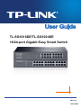
TL-SG1016DE/TL-SG1024DE
16/24-port Gigabit Easy Smart Switch
REV1.0.2
1910010980
COPYRIGHT & TRADEMARKS
Specifications are subject to change without notice.
is a registered trademark of
TP-LINK TECHNOLOGIES CO., LTD. Other brands and product names are trademarks or
registered trademarks of their respective holders.
No part of the specifications may be reproduced in any form or by any means or used to make any
derivative such as translation, transformation, or adaptation without permission from TP-LINK
TECHNOLOGIES CO., LTD. Copyright © 2014 TP-LINK TECHNOLOGIES CO., LTD. All rights
reserved.
http://www.tp-link.com
FCC STATEMENT
This equipment has been tested and found to comply with the limits for a Class A digital device,
pursuant to part 15 of the FCC Rules. These limits are designed to provide reasonable protection
against harmful interference when the equipment is operated in a commercial environment. This
equipment generates, uses, and can radiate radio frequency energy and, if not installed and used
in accordance with the instruction manual, may cause harmful interference to radio
communications. Operation of this equipment in a residential area is likely to cause harmful
interference in which case the user will be required to correct the interference at his own expense.
This device complies with part 15 of the FCC Rules. Operation is subject to the following two
conditions:
1)
2)
This device may not cause harmful interference.
This device must accept any interference received, including interference that may cause
undesired operation.
Any changes or modifications not expressly approved by the party responsible for compliance
could void the user’s authority to operate the equipment.
CE Mark Warning
This is a class A product. In a domestic environment, this product may cause radio interference, in
which case the user may be required to take adequate measures.
Продукт сертифіковано згідно с правилами системи УкрСЕПРО на відповідність вимогам
нормативних документів та вимогам, що передбачені чинними законодавчими актами
України.
III
Safety Information
When product has power button, the power button is one of the way to shut off the product;
When there is no power button, the only way to completely shut off power is to disconnect the
product or the power adapter from the power source.
Don’t disassemble the product, or make repairs yourself. You run the risk of electric shock and
voiding the limited warranty. If you need service, please contact us.
Avoid water and wet locations.
This product can be used in the following countries:
AT
BG
BY
CA
CZ
DE
DK
EE
ES
FI
FR
GB
GR
HU
IE
IT
LT
LV
MT
NL
NO
PL
PT
RO
RU
SE
SK
TR
UA
IV
CONTENTS
Package Contents ..........................................................................................................................1
Chapter 1 About this Guide...........................................................................................................2
1.1
Intended Readers .........................................................................................................2
1.2
Conventions..................................................................................................................2
1.3
Overview of This Guide ................................................................................................2
Chapter 2 Introduction ..................................................................................................................4
2.1
Overview of the Switch .................................................................................................4
2.2
Main Features...............................................................................................................4
2.3
Appearance Description ...............................................................................................4
2.3.1
Front Panel ........................................................................................................4
2.3.2
Rear Panel .........................................................................................................5
Chapter 3 Login to the Switch.......................................................................................................6
3.1
Login.............................................................................................................................6
3.2
Configuration ................................................................................................................6
Chapter 4 System .........................................................................................................................8
4.1
System Info...................................................................................................................8
4.2
IP Setting ......................................................................................................................8
4.3
User Account ................................................................................................................9
4.4
Switching ....................................................................................................................10
4.5
4.6
4.4.1
Port Setting ......................................................................................................10
4.4.2
IGMP Snooping................................................................................................12
4.4.3
Port Trunk ........................................................................................................12
Monitoring ...................................................................................................................14
4.5.1
Port Statistics ...................................................................................................14
4.5.2
Port Mirror ........................................................................................................15
4.5.3
Cable Test ........................................................................................................17
4.5.4
Loop Prevention...............................................................................................18
System Tools ..............................................................................................................18
4.6.1
Backup and Restore ........................................................................................18
4.6.2
System Reboot ................................................................................................19
4.6.3
System Reset...................................................................................................20
4.6.4
Firmware Upgrade ...........................................................................................20
Chapter 5 VLAN..........................................................................................................................22
5.1
MTU VLAN .................................................................................................................23
5.2
Port Based VLAN........................................................................................................24
5.3
802.1Q VLAN..............................................................................................................25
III
5.4
802.1Q PVID Setting ..................................................................................................27
Chapter 6 QoS............................................................................................................................29
6.1
QoS Basic...................................................................................................................30
6.2
Bandwidth Control ......................................................................................................32
6.3
Storm Control..............................................................................................................33
Appendix A: Specifications ...........................................................................................................36
Appendix B: Configuring the PCs .................................................................................................37
IV
Package Contents
The following items should be found in your box:
One 16/24-port Gigabit Easy Smart Switch
One power cord
Two mounting brackets and other fittings
Installation Guide
Resource CD for TL-SG1016DE/TL-SG1024DE switch, including:
This User Guide
Easy Smart Configuration Utility.exe
Easy Smart Configuration Utility User Guide
Other Helpful Information
Note:
Make sure that the package contains the above items. If any of the listed items are damaged or
missing, please contact your distributor.
1
Chapter 1 About this Guide
This User Guide contains information for setup and management of TL-SG1016DE/TL-SG1024DE
16/24-port Gigabit Easy Smart Switch. Please read this guide carefully before operation.
1.1 Intended Readers
This Guide is intended for network managers familiar with IT concepts and network terminologies.
1.2 Conventions
In this Guide the following conventions are used:
The switch or TL-SG1016DE/TL-SG1024DE mentioned in this Guide stands for
TL-SG1016DE/TL-SG1024DE
16/24-port
Gigabit
Easy
Smart
Switch
without
any
explanation.
Tips:
The two devices of TL-SG1016DE and TL-SG1024DE are sharing this User Guide. For simplicity,
we will take the operation on TL-SG1016DE for example throughout the configuration chapters.
TL-SG1016DE and TL-SG1024DE just differ in the number of LED indicators and ports and all
figures in this guide are of TL-SG1016DE.
Menu Name→Submenu Name→Tab page indicates the menu structure. System→System
Info→System Summary means the System Summary page under the System Info menu
option that is located under the System menu.
Bold font indicates a button, a toolbar icon, menu or menu item.
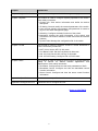
Symbols in this Guide:
Symbol
Description
Note:
Ignoring this type of note might result in a malfunction or damage to the device.
Tips:
This format indicates important information that helps you make better use of your
device.
1.3 Overview of This Guide
Chapter
Introduction
Chapter 1 About This Guide
Introduces the guide structure and conventions.
Chapter 2 Introduction
Introduces the features, application
TL-SG1016DE/TL-SG1024DEswitch.
2
and
appearance
of
Chapter
Introduction
Chapter 3 Login to the Switch
Introduces how to log on to the Web management page.
Chapter 4 System
This module is used to configure system properties of the switch.
Here mainly introduces:
System Info: View device information and define the device
description.
IP Setting: Get and modify the network parameters of the switch.
User Account: Modify the username and password for users to
log on to the Web management page.
Switching: Configure the basic functions of the switch.
Monitoring: Monitor the traffic information of the switch, and
provide the convenient method to locate and solve the network
problem.
System Tools: Manage the configuration file of the switch.
Chapter 5 VLAN
This module is used to configure VLANs to control broadcast in
LANs. Here mainly introduces:
MUT VLAN: Set the MTU VLAN mode.
Port Based VLAN: Set the Port-Based VLAN mode
802.1Q VLAN: Set the 802.1Q Tag VLAN mode.
802.1Q PVID Setting: Configure 802.1Q PVID value.
Chapter 6 QoS
This module is used to configure QoS function to provide different
quality of service for various network applications and
requirements. Here mainly introduces:
QoS Basic: Configure and view the basic parameters of QoS.
Bandwidth Control: Configure and view the bandwidth control
function information.
Storm Control: Configure and view the storm control function
information.
Appendix A Specifications
Lists the hardware specifications of the switch.
Appendix B Configure the PCs
Introduces how to configure the PCs.
Return to CONTENTS
3
Chapter 2 Introduction
Thanks for choosing the TL-SG1016DE/TL-SG1024DE 16/24-port Gigabit Easy Smart Switch!
2.1 Overview of the Switch
The TL-SG1016DE/TL-SG1024DE 16/24-port Gigabit Easy Smart Switch is an ideal upgrade from
an unmanaged switch, designed for Small and Medium Business networks that require simple
network management. Network administrators can effectively monitor traffic via Port Mirroring,
Loop Prevention and Cable Test features. To optimize traffic on your business network, they offer
both port and tag based QoS to keep latency-sensitive traffic moving smoothly and jitter-free.
Additionally, port-based, tag-based and MTU VLAN can improve security and meet more network
segmentation requirements. Moreover, with the innovative energy-efficient technology, they are
eco-friendly solution for your business network.
2.2 Main Features
Resiliency and Availability
+ Multicast snooping automatically prevents flooding of IP multicast traffic.
Layer 2 Switching
+ Supports up to 32 VLANs simultaneously (out of 4K VLAN IDs).
Quality of Service
+ Supports L2/L3 granular CoS with 4 priority queues per port.
+ Rate limiting confines the traffic flow accurately according to the preset value.
Manageability
+ Supports Easy Smart Configuration Utility for central configuration and management.
+ Supports web access.
+ Port Mirroring enables monitoring selected ingress/egress traffic.
Note:
For details about Easy Smart Configuration Utility, please refer to the User Guide of the Easy
Smart Configuration Utility in the Resource CD.
2.3 Appearance Description
2.3.1 Front Panel
The front panel of TL-SG1016DE is shown as Figure 2-1.
Figure 2-1 Front Panel of TL-SG1016DE
The front panel of TL-SG1024DE is shown as Figure 2-2.
4
Figure 2-2 Front Panel of TL-SG1024DE
The following parts are located on the front panel of the switch:
Reset: With the switch powered on, press this button for five seconds or above to reset the
software setting back to factory default setting.
1000Mbps Ports: Designed to connect to the device with a bandwidth of 10Mbps, 100Mbps or
1000Mbps. Each has a corresponding 1000Mbps LED and link/Act LED.
LEDs
Name
Status
On
Power
1000Mbps
Link/Act
Flashing
Indication
Power is on.
Power supply is abnormal.
Off
Power is off or power supply is abnormal.
On
A 1000Mbps device is connected to the corresponding port.
Off
A 10/100Mbps device or no device is connected to the
corresponding port.
On
A device is connected to the corresponding port but no activity.
Flashing
Off
Data is being transmitted or received.
No device is connected to the corresponding port.
2.3.2 Rear Panel
The rear panel of TL-SG1016DE/TL-SG1024DE features a power socket and a Grounding
Terminal (marked with ).
Figure 2-3 Rear Panel of TL-SG1016DE
Grounding Terminal: TL-SG1016DE/TL-SG1024DE already comes with Lightning Protection
Mechanism. You can also ground the switch through the PE (Protecting Earth) cable of AC cord
or with Ground Cable.
AC Power Socket: Connect the female connector of the power cord here, and the male
connector to the AC power outlet. Please make sure the voltage of the power supply meets the
requirement of the input voltage (100-240V~ 50/60Hz 0.6A).
Return to CONTENTS
5
Chapter 3 Login to the Switch
3.1 Login
1) To access the configuration utility, open a web-browser and type the default address
http://192.168.0.1 in the address field of the browser, then press the Enter key.
Figure 3-1 Web-browser
Tips:
To log in to the switch, the IP address of your PC should be set in the same subnet addresses of
the switch. The IP address is 192.168.0.x ("x" is any number from 2 to 254), Subnet Mask is
255.255.255.0. For the detailed instructions as to how to do this, please refer to Appendix B.
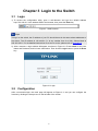
2) After a moment, a login window will appear, as shown in Figure 3-2. Enter admin for the User
Name and Password, both in lower case letters. Then click the Login button or press the Enter
key.
Figure 3-2 Login
3.2 Configuration
After a successful login, the main page will appear as Figure 3-3, and you can configure the
function by clicking the setup menu on the left side of the screen.
6
Figure 3-3 Main Setup-Menu
Note:
Clicking Apply can only make the new configurations effective before the switch is rebooted. If
you want to keep the configurations effective even the switch is rebooted, please click Save
Config. You are suggested to click Save Config before cutting off the power or rebooting the
switch to avoid losing the new configurations.
Return to CONTENTS
7
Chapter 4 System
The System module is mainly for basic settings of the switch, including six submenus: System
Info, IP Setting, User Account, Switching, Monitoring and System Tools.
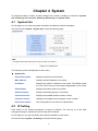
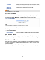
4.1 System Info
On this page you can view the system information and define the device description.
Choose the menu System→System Info to load the following page.
Figure 4-1 System Info
The following entries are displayed on this screen:
System Info
Device Description:
Displays the device model number.
MAC Address:
Displays the MAC address of the switch.
IP Address:
Displays the system IP address of the switch. The default system
IP is 192.168.0.1 and you can change it appropriate to your needs.
Subnet Mask:
Displays the subnet mask of the switch.
Default Gateway:
Displays the default gateway of the switch.
Firmware Version:
Displays the installed software version number.
Hardware Version:
Displays the installed device hardware version number.
Device Description:
Give a description to the device for identification.
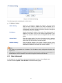
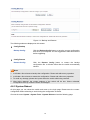
4.2 IP Setting
Each device in the network possesses a unique IP Address. You can log on to the Web
management page to operate the switch using this IP Address.
On this page you can get and modify the network parameters of the switch.
Choose the menu System→IP Setting to load the following page.
8
Figure 4-2 IP Address Setting
The following entries are displayed on this screen:
IP Address Setting
DHCP Setting:
Allows you to enable or disable the switch to serve as DHCP
client. If DHCP client is enabled, the switch will obtain the IP
address, subnet mask and default gateway from the DHCP server
automatically; otherwise, these three items should be configured
manually. By default, it is disabled.
IP Address:
Specify the system IP address of the switch. The default system IP
address is 192.168.0.1 and you can change it appropriate to your
needs. The switch IP address must be compliant with the subnet
layout.
Subnet Mask:
Enter the subnet mask of the switch. Subnet mask is an address
code that determines the size of the network. By default, the
switch uses 255.255.255.0 as the subnet mask.
Default Gateway:
Enter the default gateway of the switch. Gateway serves as the
default destination where the packet is to be forwarded when its
destination IP address is not within the switch’s subnet.
Note:
1. The switch only possesses an IP address. The IP address newly configured will replace the
original one.
2. Changing the IP address to a different IP segment will interrupt the network communication, so
please keep the new IP address in the same IP segment with the local network.
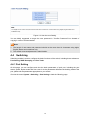
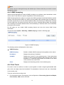
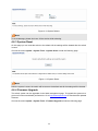
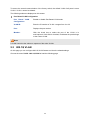
4.3 User Account
On this page you can modify the username and password in order to refuse illegal users.
Choose the menu System→User Account to load the following page.
9
Figure 4-3 User Account Setting
You are kindly suggested to retype the new password in "Confirm Password" box instead of
copying in order to avoid mistakes.
Note:
1. The length of user name and password should not be more than 16 characters using digits,
English letters and underlines only.
2. The default username/password is admin/admin.
4.4 Switching
Switching module is used to configure the basic functions of the switch, including three submenus:
Port Setting, IGMP Snooping and Port Trunk.
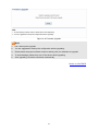
4.4.1 Port Setting
On this page, you can configure and view the basic parameters of each port, including the port
status, speed, duplex mode and flow control. As the parameters will affect the working mode of the
port, please set the parameters appropriate to your needs.
Choose the menu System→Switching→Port Setting to load the following page.
10
Figure 4-4 Port Setting
The following entries are displayed on this screen:
Port Setting
Port:
Select the desired port for configuration. It is multi-optional.
Status:
Allows you to enable of disable the port. “Enable" indicates that
the port is operational and "Disable" indicates the port is
non-operational. If a port is unused for a long time, its status can
be set to “Disable” to cut down the energy cost.
Speed/Duplex:
Select the Speed and Duplex mode for the port. The device
connected to the switch should be in the same Speed and Duplex
mode with the switch. Available field values are “Auto”, “10M HD”,
“10M FD”, “100M HD”, “100M FD” and “1000M FD”. "HD" stands
for Half-Duplex and "FD" stands for Full-Duplex. "Auto" means
auto negotiation.
Flow Control:
Allows you to On/Off the Flow Control feature. When “On” is
selected, the switch can synchronize the speed with its peer to
avoid the packet loss caused by congestion.
11
Note:
The switch cannot be managed through the disabled port. Please enable the port which is used to
manage the switch.
4.4.2 IGMP Snooping
Internet Group Management Protocol (IGMP) snooping is a multicast control mechanism, which
can be used on the switch for dynamic registration of the multicast group.
IGMP Snooping allows the switch to recognize the IGMP messages transmitted between network
stations or devices and an IGMP host. When receiving IGMP report message from the IGMP host,
the switch will add the port to the multicast address table; when listening to IGMP leave message
from the IGMP host, the switch will remove the port from the multicast address table. By managing
and controlling the multicast address table, the broadcasting of multicast traffic can be effectively
prevented in the network.
On this page you can enable IGMP snooping feature and view the current IGMP Group
information.
Choose the menu System→Switching→IGMP Snooping to load the following page.
Figure 4-5 IGMP Snooping
The following entries are displayed on this screen:
IGMP Snooping
IGMP Snooping:
Enable or disable IGMP snooping function globally on the switch.
IP Address:
Displays the multicast IP address.
VLAN ID:
Displays the VLAN ID of the multicast group. If the packet does
not carry VLAN ID, then here displays the PVID of the port. All port
members of a multicast group should be divided to the same
VLAN, and have the same PVID.
Ports:
Displays the forwarding port list of the multicast group.
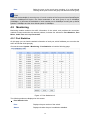
4.4.3 Port Trunk
Port trunk is used to combine a number of ports together to make a single high-bandwidth data
path, which can highly extend the bandwidth. The bandwidth of the trunk is the sum of bandwidth
of its member ports.
There are some rules on using trunk:
For the member ports in a trunk group, their configuration of Port setting (Speed and Duplex,
Flow Control), QoS must be the same.
12
For the newly joined member ports in a trunk group, their default setting of Port setting
(Speed and Duplex, Flow Control), QoS will be configured the same as that of the first
member port in the trunk group.
The trunk member ports cannot be set as mirroring port.
Before setting the trunk, its member ports should be divided to the same VLAN, and have the
same PVID and drop the untagged packet rule. Change of the trunk setting will not affect the
VLAN setting.
If the port trunk is needed, you are suggested to configure the port trunk function here before
configuring the other functions for the member ports.
On this page, you can configure and view the information of the trunk group of the switch.
Choose the menu System→Switching→Port Trunk to load the following page.
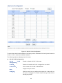
Figure 4-6 Trunk Group Setting
Here you can configure and view the port parameters.
Trunk Group Setting
Group ID:
Select an identified number for the trunk group from the
drop-down list.
13
Port:
Select the port as the trunk group member. It is multi-optional.
Clearing all the ports of the trunk group will delete this trunk group.
Tips:
Calculate the bandwidth for a trunk group: If a trunk consists of the four ports whose Speed/Duplex
mode is 1000Mbps/Full Duplex, the whole bandwidth of the trunk group is up to 8000Mbps
(2000Mbps * 4) because the bandwidth of each member port is 2000Mbps counting the up-linked
speed of 1000Mbps and the down-linked speed of 1000Mbps.
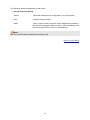
4.5 Monitoring
Monitoring module monitors the traffic information of the switch, and provides the convenient
method to locate and solve the network problem, includes four submenus: Port Statistics, Port
Mirror, Cable Test and Loop Prevention.
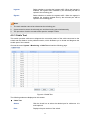
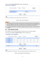
4.5.1 Port Statistics
On this page you can view the statistic information of each port, which facilitates you to monitor the
traffic and locate faults promptly.
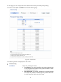
Choose the menu System→Monitoring→Port Statistics to load the following page.
Figure 4-7 Port Statistics Info
The following entries are displayed on this screen:
Port Statistics Info
Port:
Displays the port number of the switch.
Status:
Displays whether the port is enabled or disabled.
14
Link Status:
Displays whether the port is link up or link down.
TxGoodPkt:
Displays the number of good packets transmitted on the port. The
error packets are not counted in.
TxBadPkt:
Displays the number of error packets transmitted on the port.
RxGoodPkt:
Displays the number of good packets received on the port. The
error packets are not counted in.
RxBadPkt:
Displays the number of error packets received on the port.
4.5.2 Port Mirror
Port mirror functions to monitor and mirror network traffic by forwarding copies of incoming and
outgoing packets from one/multiple ports (mirrored port) to a specific port (mirroring port). Usually,
the mirroring port is connected to a data diagnosis device, which is used to analyze the mirrored
packets for monitoring and troubleshooting the network.
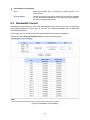
Choose the menu System→Monitoring→Port Mirror to load the following page.
15
Figure 4-8 Port Mirror
The following entries are displayed on this screen:
Port Mirror
Port Mirror:
Allows you to enable or disable the port mirror feature of the
specified port.
Mirroring Port:
Select a port from the pull-down list as the mirroring port.
Mirrored Port
Mirrored Port:
Select a port from the pull-down list as the mirrored port to monitor
the traffic. Trunk member cannot be defined here. It is
multi-optional.
16
Ingress:
Select whether to monitor the ingress traffic. When the ingress is
enabled, the ingress traffic received by the mirrored port will be
copied to the mirroring port.
Egress:
Select whether to monitor the egress traffic. When the egress is
enabled, the outgoing packets sent by the mirrored port will be
copied to the mirroring port.
Note:
1.
The trunk member cannot be selected as the mirroring port.
2.
A port cannot be set as the mirrored port and the mirroring port simultaneously.
3.
The port mirror function can take effect span the multiple VLANs.
4.5.3 Cable Test
This switch provides cable test to diagnose the connection status of the cable connected to the
switch and the distance to the problem location, which facilitates you to locate and diagnose the
trouble spot of the network.
Choose the menu System→Monitoring→Cable Test to load the following page.
Figure 4-9 Cable Test
The following entries are displayed on this screen:
Cable Test
Select:
Click the check box to select the desired port for cable test. It is
multi-optional.
Port:
Displays the port number of the switch.
17
Test Result:
Displays the connection status of the cable connected to the port.
The test results of the cable include “No Cable”, “Open”,
“Short”, ”Open Short”, “Normal”, “Cro Cable” and “others”.
Cable Fault
Distance(m):
Displays the error length (in meters) of the cable.
Note:
The test result is just for your reference.
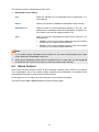
4.5.4 Loop Prevention
With loop prevention feature enabled, the switch can detect loops using loop detection packets.
When a loop is detected, the switch will block the corresponding port automatically.
Choose the menu System→Monitoring→Loop Prevention to load the following page.
Figure 4-10 Loop Function Setting
The following entries are displayed on this screen:
Loop Prevention Setting
Loop Prevention:
Allows you to enable or disable loop prevention function globally.
4.6 System Tools
The System Tools function, allowing you to manage the configuration file of the switch, can be
implemented on Backup and Restore, System Reboot, System Reset and Firmware Upgrade
pages.
4.6.1 Backup and Restore
On this page you can download the current configuration and save it as a file to your computer for
your future configuration to upload a backup configuration file to restore your switch to this
previous configuration.
Choose the menu System→System Tools→Backup and Restore to load the following page.
18
Figure 4-11 Backup and Restore
The following entries are displayed on this screen:
Config Backup
Backup Config:
Click the Backup Config button to save the current configuration
as a file to your computer. You are suggested to take this measure
before upgrading.
Config Restore
Restore Config:
Click the Restore Config button to restore the backup
configuration file. It will take effect after the switch automatically
reboots.
Note:
1. It will take a few minutes to backup the configuration. Please wait without any operation.
2. It will take a few minutes to restore the configuration. Please wait without any operation.
3. To avoid any damage, please don’t power down the switch while being restored.
4. After being restored, the current settings of the switch will be lost. Wrong uploaded
configuration file may cause the switch unmanaged.
4.6.2 System Reboot
On this page you can reboot the switch and return to the login page. Please save the current
configuration before rebooting to avoid losing the configuration unsaved.
Choose the menu System→System Tools→System Reboot to load the following page.
19
Figure 4-12 System Reboot
Note:
To avoid damage, please don't turn off the device while rebooting.
4.6.3 System Reset
On this page you can reset the switch to the default. All the settings will be cleared after the switch
is reset.
Choose the menu System→System Tools→System Reset to load the following page.
Figure 4-13 System Reset
Note:
After the system is reset, the switch will be reset to the default and all the settings will be cleared.
4.6.4 Firmware Upgrade
The switch system can be upgraded via the Web management page. To upgrade the system is to
get more functions and better performance. Go to http://www.tp-link.com to download the updated
firmware.
Choose the menu System→System Tools→Firmware Upgrade to load the following page.
20
Figure 4-14 Firmware Upgrade
Note:
1.
Don’t interrupt the upgrade.
2.
You are suggested to backup the configuration before upgrading.
3.
Please select the proper software version matching with your hardware to upgrade.
4.
To avoid damage, please don't turn off the device while upgrading.
5.
After upgrading, the device will reboot automatically.
Return to CONTENTS
21
Chapter 5 VLAN
The traditional Ethernet is a data network communication technology based on CSMA/CD (Carrier
Sense Multiple Access/Collision Detect) via shared communication medium. Through the
traditional Ethernet, the overfull hosts in LAN will result in serious collision, flooding broadcasts,
poor performance or even breakdown of the Internet. Though connecting the LANs through
switches can avoid the serious collision, the flooding broadcasts cannot be prevented, which will
occupy plenty of bandwidth resources, causing potential serious security problems.
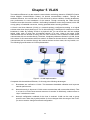
A Virtual Local Area Network (VLAN) is a network topology configured according to a logical
scheme rather than the physical layout. The VLAN technology is developed for switches to control
broadcast in LANs. By creating VLANs in a physical LAN, you can divide the LAN into multiple
logical LANs, each of which has a broadcast domain of its own. Hosts in the same VLAN
communicate with one another as if they are in a LAN. However, hosts in different VLANs cannot
communicate with one another directly. Therefore, broadcast packets are limited in a VLAN. Hosts
in the same VLAN communicate with one another via Ethernet whereas hosts in different VLANs
communicate with one another through the Internet devices such as router, the Lay3 switch, etc.
The following figure illustrates a VLAN implementation.
Figure 5-1 VLAN implementation
Compared with the traditional Ethernet, VLAN enjoys the following advantages.
(1) Broadcasts are confined to VLANs. This decreases bandwidth utilization and improves
network performance.
(2) Network security is improved. VLANs cannot communicate with one another directly. That
is, a host in a VLAN cannot access resources in another VLAN directly, unless routers or
Layer 3 switches are used.
(3) Network configuration workload for the host is reduced. VLAN can be used to group
specific hosts. When the physical position of a host changes within the range of the VLAN,
you do not need to change its network configuration.
22
There are 3 types of VLAN modes supported in the switch:
1. MTU VLAN
MTU VLAN (Multi-Tenant Unit VLAN) defines an uplink port which will build up several VLANs with
each of the other ports. Each VLAN contains two ports, the uplink port and one of the other ports in
the switch, so the uplink port can communicate with any other port but other ports cannot
communicate with each other.
2. Port Based VLAN
VLANs are divided based on ports. By default, the Port Based VLAN is enabled.
3. 802.1Q VLAN
The IEEE 802.1Q protocol defines a new format of the frame; it adds a Tag header in the original
Ethernet frame, as follows:
Figure 5-2 IEEE 802.1Q frame
VLAN tags in the packets are necessary for the switch to identify packets of different VLANs. The
switch works at the data link layer in OSI model and it can identify the data link layer encapsulation
of the packet only, so you can add the VLAN tag field into the data link layer encapsulation for
identification.
IEEE 802.1Q Tag VLAN is divided by VLAN ID (VID). On receiving a frame, the switch checks the
VID in the Tag header of the frame to decide which VLAN it belongs to. If the receiving frame
doesn’t contain the Tag header, the switch will assign a Tag to the frame, using the PVID of the
port as its VID.
In this User Guide, the tagged packet refers to the packet with VLAN tag whereas the untagged
packet refers to the packet without VLAN tag.
The VLAN module is mainly for VLAN configuration, including four submenus: MTU VLAN, Port
Based VLAN, 802.1Q VLAN and 802.1Q PVID Setting.
5.1 MTU VLAN
On this page you can choose to enable MTU VLAN mode and configure VLANs.
23
Choose the menu VLAN→MTU VLAN to load the following page.
Figure 5-3 MTU VLAN Configuration
Note:
1.
The uplink port will form several VLANs with each of the other ports. Each VLAN contains two
ports, the uplink port and one of the other ports in the switch, thus the uplink port can
communicate with any other port but other ports cannot communicate with each other.
2.
For the first time the MTU VLAN mode is enabled, the switch will set port 1 as the uplink port
by default.
5.2 Port Based VLAN
On this page you can configure Port Based VLAN feature and view the related settings.
Choose the menu VLAN→Port Based VLAN to load the following page.
Figure 5-4 Port Based VLAN Configuration
24
To ensure the normal communication of the factory switch, the default VLAN of all ports is set to
VLAN1. VLAN 1 cannot be deleted.
The following entries are displayed on this screen:
Port Based VLAN Configuration
Port Based VLAN
Configuration:
Enable or disable Port Based VLAN mode.
VLAN ID:
Enter the ID number of VLAN. It ranges from 2 to 32.
Port:
Displays the port number.
Member:
Click the check box to select the port of the VLAN. It is
multi-optional. If this field is checked, it indicates the port belongs
to the current VLAN.
Note:
A VLAN cannot be the subset or superset of the other VLANs.
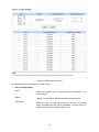
5.3 802.1Q VLAN
On this page you can configure 802.1Q VLAN feature and view the related settings.
Choose the menu VLAN→802.1Q VLAN to load the following page.
25
Figure 5-5 802.1Q VLAN Configuration
To ensure the normal communication of the factory switch, the default VLAN of all ports is set to be
VLAN1. VLAN 1 cannot be modified or deleted.
The following entries are displayed on this screen:
802.1Q VLAN Configuration
802.1Q
VLAN
Configuration:
Enable or disable 802.1Q VLAN mode.
VLAN ID:
Enter the ID number of VLAN. It ranges from 2 to 4094.
VLAN Name:
Give a name to the VLAN for identification.
Port:
Displays the port number.
Untagged:
Click the check box to configure the egress rule of the traffic on
this port as untagged. The switch drops the tag header before
sending the packet.
26
Tagged:
Click the check box to configure the egress rule of the traffic on
this port as tagged. The switch adds the tag header before
sending the packet.
Not Member:
Click the check box to exclude the port from the current VLAN.
5.4 802.1Q PVID Setting
PVID (Port Vlan ID) is the default VID of the port. When the switch receives an un-VLAN-tagged
packet, it will add a VLAN tag to the packet according to the PVID of its received port and forward
the packets.
When creating VLANs, the PVID of each port, indicating the default VLAN to which the port
belongs, is an important parameter with the following two purposes:
(1) When the switch receives an un-VLAN-tagged packet, it will add a VLAN tag to the packet
according to the PVID of its received port
(2) PVID determines the default broadcast domain of the port, i.e. when the port receives UL
packets or broadcast packets, the port will broadcast the packets in its default VLAN.
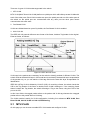
On this page you can configure PVID of the specified port. By default, the PVID of all ports is 1.
Choose the menu VLAN→802.1Q VLAN Port Setting to load the following page.
Figure 5-6 802.1Q VLAN Port Setting
27
The following entries are displayed on this screen:
802.1Q VLAN Port Setting
Select:
Select the desired port for configuration. It is multi-optional.
Port:
Displays the port number.
PVID:
Enter a PVID number for the port. When adding the tag header to
the received untagged packet, the switch will automatically uses
this PVID value as the VLAN ID of the added tag.
Note:
802.1Q VLAN should be enabled before setting PVID.
Return to CONTENTS
28
Chapter 6 QoS
QoS (Quality of Service) functions to provide different quality of service for various network
applications and requirements and optimize the bandwidth resource distribution so as to provide a
network service experience of a better quality.
QoS
This switch classifies the ingress packets, maps the packets to four different priority queues and
then forwards the packets according to Strict-Priority scheduling algorithms to implement QoS
function.
Figure 6-1 QoS function
Traffic classification: Identifies packets conforming to certain characters according to certain
rules.
Map: This switch supports four priority queues. The priority queues are labeled as 1(Lowest),
2(Normal), 3(Medium) and 4(Highest), among them the bigger the value, the higher the
priority. The ingress packets are mapped to four different priority queues based on the QoS
modes. This switch implements two QoS modes based on port and on 802.1P.
Queue scheduling algorithm: When the network is congested, the problem that many packets
compete for resources must be solved, usually in the way of queue scheduling. In both
port-based and 802.1P QoS modes, this switch adopts Strict-Priority scheduling algorithm. In
Strict-Priority scheduling algorithm, the queue with higher priority will occupy the whole
bandwidth. Packets in the queue with lower priority are sent only when the queue with higher
priority is empty.
QoS Mode
This switch implements two QoS modes based on port and on 802.1P. By default, the QoS mode
based on port is enabled and the other one is optional.
29
1. Port Based
When port-base QoS mode is enabled, the user can manually map the ingress packets of the port
to four different priority queues. After that, the switch will preferentially send packets in the queue
with higher priority, and only when the queue with higher priority is empty, packets in the queue
with lower priority are sent.
2. 802.1P Based
Figure 6-2 802.1Q frame
As shown in the figure above, each 802.1Q Tag has a Pri field, comprising 3 bits. The 3-bit priority
field is 802.1p priority in the range of 0 to 7. The 802.1p priority value determines how the switch
maps the ingress packets to the priority queues. The mapping relationship between eight 802.1p
priority value and priority queues is shown as follows:
Figure 6-3 Map 802.1P priority
Priority 1 and 2 are assigned to the 1 (Lowest) priority queue.
Priority 0 and 3 are assigned to the 2 (Normal) priority queue.
Priority 4 and 5 are assigned to the 3 (Medium) priority queue.
Priority 6 and 7 are assigned to the 4 (Highest) priority queue.
When 802.1P QoS mode is enabled, the switch will automatically map the ingress packets to
priority queues based on the 802.1p priority and the above mapping relationship. After that, the
switch will preferentially send packets in the queue with higher priority, and only when the queue
with higher priority is empty, packets in the queue with lower priority are sent. As for the untagged
packets, the switch will forward it according to the default port-based QoS mode.
The QoS module is mainly for priority configuration and traffic control, including three submenus:
QoS Basic, Bandwidth Control and Storm Control.
6.1 QoS Basic
This switch classifies the ingress packets, maps the packets to different priority queues and then
forwards the packets to implement QoS function.
This switch implements two priority modes based on port and on 802.1P. The port-based QoS mode
supports four priority queues. The port priority queues are labeled as 1, 2, 3, and 4.
30
On this page you can configure and view QoS mode and the port-based priority setting.
Choose the menu QoS→QoS Basic to load the following page.
Figure 6-4 QoS Basic
The following entries are displayed on this screen:
Global Config
QoS Mode:
Select the desired QoS mode.
Port Based: The switch classifies the ingress packets and
maps the packets to different priority queues based on which
port the packets come from.
802.1p Based: The switch classifies the ingress packets
and maps the packets to different priority queues based on
the 802.1p priority field in the 802.1Q tag.
31
Port-based Priority Setting
Port:
Select the desired port to configure its priority queue. It is
multi-optional.
Priority Queue:
Specify the priority queue the packets from the port are mapped
to. The priorities are labeled as 1~4 and among them the bigger
the value, the higher the priority.
6.2 Bandwidth Control
Bandwidth control functions to control the ingress/egress traffic rate on each port via configuring
the available bandwidth of each port. In this way, the network bandwidth can be reasonably
distributed and utilized.
On this page you can configure and view the bandwidth control function information.
Choose the menu QoS→Bandwidth Control to load the following page.
Figure 6-5 Bandwidth Control Setting
32
The following entries are displayed on this screen:
Bandwidth Control Setting
Port:
Select the desired port for bandwidth control configuration. It is
multi-optional.
Status:
Allows you to enable or disable the bandwidth control function..
Rate(Kbit/sec):
Select the rate for receiving/sending packets on the port. The
packet traffic exceeding the rate will be discarded. It ranges from
0 to 100000, and must be integral multiple of 64.
Type:
Select to control the ingress/egress traffic rate on each port. It is
multi-optional.
Ingress: If the rate for receiving packets on the port exceeds
the set rate, the packets will be discarded.
Egress: If the rate for sending packets on the port exceeds
the set rate, the packets will be discarded.
Note:
1.
If you enable ingress bandwidth control feature for the storm control-enabled port, storm
control feature will be disabled for this port.
2.
When egress bandwidth control feature is enabled for one or more ports, you are suggested
to disable the flow control on each port to ensure the switch works normally.
6.3 Storm Control
Storm control function allows the switch to filter broadcast, multicast and UL frame in the network.
If the transmission rate of the chosen packets exceeds the set bandwidth, the packets will be
automatically discarded to avoid network broadcast storm.
On this page you can configure and view the storm control function information.
Choose the menu QoS→Storm Control to load the following page.
33
Figure 6-6 Storm Control Setting
The following entries are displayed on this screen:
Storm Control Setting
Port:
Select the desired port for storm control configuration. It is
multi-optional.
Status:
Allows you to enable or disable the storm control function.
Total Rate:
Select the rate for receiving packets on the port. The packet
traffic exceeding the rate will be discarded. It ranges from 0 to
100000, and must be integral multiple of 64.
34
Included
Type:
Storm
Select to filter broadcast/multicast/UL frame in the network, if the
transmission rate of the chosen packets exceeds the set rate, the
packets will be automatically discarded to avoid network
broadcast storm. It is multi-optional.
UL-Frame: If UL-Frame packets traffic exceeds the rate on
the port, they will be discarded.
Multicast: If multicast packets traffic exceeds the rate on the
port, they will be discarded.
Broadcast: If broadcast packets traffic exceeds the rate on
the port, they will be discarded.
Note:
If you enable storm control feature for the ingress rate control-enabled port, the ingress rate
control feature will be disabled for this port.
Return to CONTENTS
35
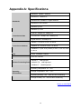
Appendix A: Specifications
IEEE802.3 10Base-T Ethernet
IEEE802.3u 100Base-TX
Standards
IEEE802.3ab 1000Base-T Gigabit Ethernet
IEEE802.3x Flow Control
IEEE802.1p QoS
IEEE802.1q VLAN
Ethernet: 10Mbps HD, 20Mbps FD
Transmission Rate
Fast Ethernet: 100Mbps HD, 200Mbps FD
Gigabit Ethernet: 2000Mbps FD
10Base-T: UTP/STP of Cat. 3 or above
Transmission Medium
100Base-TX: UTP/STP of Cat. 5 or above
1000Base-T: 4-pair UTP (≤100m) of Cat. 5, Cat. 5e, Cat.6
or above
LED
Power, 1000Mbps, Link/Act
Transmission Method
Store and Forward
10BASE-T:14881pps/port
Packets Forwarding Rate
100BASE-TX:148810pps/port
1000Base-T:1488095pps/port
Operating Temperature: 0℃~ 40℃
Operating
Environment
Storage Temperature: -40℃ ~ 70℃
Operating Humidity: 10% ~ 90% RH Non-condensing
Storage Humidity: 5% ~ 90% RH Non-condensing
Return to CONTENTS
36
Appendix B: Configuring the PCs
In this section, we’ll introduce how to install and configure the TCP/IP correctly in Windows 2000.
First make sure your Ethernet Adapter is working, refer to the adapter’s manual if necessary.
1)
On the Windows taskbar, click the Start button, and then click Control Panel.
2)
Click the Network and Internet Connections icon, and then click on the Network
Connections tab in the appearing window.
3)
Right click the icon that showed below, select Properties on the prompt page.
Figure B-1
4)
In the prompt page that showed below, double click on the Internet Protocol (TCP/IP).
Figure B-2
37
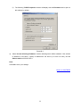
5)
The following TCP/IP Properties window will display and the IP Address tab is open on
this window by default.
Figure B-3
6)
Select Use the following IP address. And the following items will be available. If the switch's
IP address is 192.168.0.1, specify IP address as 192.168.0.x (x is from 2 to 254), and the
Subnet mask as 255.255.255.0.
Now:
Click OK to save your settings.
Return to CONTENTS
38