1
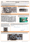
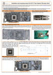
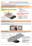
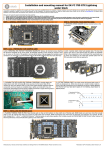
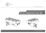
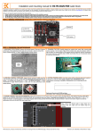
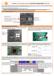
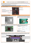
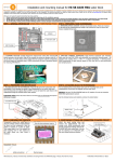
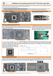
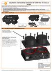
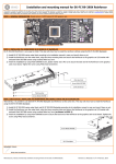
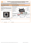
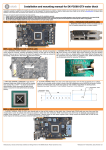
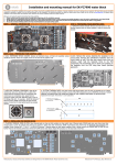
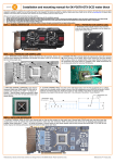
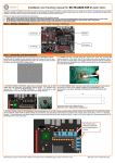
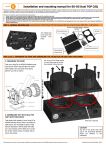
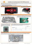
Installation and mounting manual for EK-FC Titan SE water block
This product is intended for installation only by expert users. Please consult with a qualified technician for installation. Improper installation may result in damage to your equipment. EK Water Blocks assumes no liability
whatsoever, expressed or implied, for the use of these products, nor their installation. The following instructions are subject to change without notice. Please visit our web site at www.ekwb.com for updates. Before
installation of this product please read important notice, disclosure and warranty conditions printed on the back of the box.
Before you start using this product please follow these basic guidelines:
1. Please carefully read the manual before through before beginning with the installation process!
2. Please remove your motherboard from the computer to assure safest mounting process in order to prevent any possible damages to your CPU and/or motherboard’s circuit board (PCB).
3. The EK High Flow and EK-PSC type fittings require only a small amount of force to screw them firmly in place since the liquid seal is ensured by the rubber O-ring gaskets.
4. The use of corrosion inhibiting coolants is always recommended for any liquid cooling system.
STEP 1: GENERAL INFORMATION. Sample picture of GeForce GTX Titan series graphics card.
STEP 2: PREPARING YOUR GRAPHIC CARD.
1. REMOVING STOCK COOLER: Remove encircled screw on the
bracket (required only on certain models):
STEP 2 cont.: PREPARING YOUR GRAPHIC CARD
2 cont.. REMOVING STOCK COOLER. Remove all encircled screws. All heat sink assembly screws 2. CLEANING THE PCB. Carefully detach the original stock cooler
should be removed, including self-adhesive washers on both sides of the PCB (if present). There are up to
19 screws on the back of the graphics card. Depending on the manufacturer a Torx T6 head screwdriver
might be needed to complete this step.
3. APPLYING THERMAL COMPOUND. Wipe off the
remains (by using non–abrasive cloth or qtip) of the
original thermal compound until the components and
circuit board are completely clean. Apply thermal
compound: lightly coat NVIDIA GPU chip with enclosed
EK-TIM Ectotherm thermal grease. EKWB recommends to
apply thermal grease in cross form for best performance
(see sample picture).
after removing all screws securing it to the board. Wipe off the
remains (by using non–abrasive cloth or qtip, as shown on sample
photo) of the original thermal compound until the components and
circuit board are completely clean. EKWB recommends the use of
denatured alcohol for removing TIM leftovers.
4. CUTTING THERMAL PADS. Your block comes with thermal pads, some of which are already pre-cut. Others
have to be cut to smaller chunks in order to cover all the VRM components such as MOSFETs and drivers. PLEASE
REMOVE THE PROTECTIVE FOIL FROM BOTH SIDES OF THE THERMAL PADS PRIOR TO INSTALLATION.
Replacement thermal pads: Thermal Pad D – 0.5mm (RAM 8x), Thermal Pad B – 0.5mm (75x50mm)
1: Thermal pad D – 0.5mm
(for memory IC):
1 1
1 1 1
1
1
1
2
2: Thermal pad B – 0.5mm
(for VRM/MOSFET):
STEP 3: INSTALLING THE WATER BLOCK
1. PLACING THERMAL PADS ON PCB. Place thermal pads on chips so that numbers on chips match size of thermal pads. EKWB made sure users have more than
enough pads to cover all surfaces that need to be covered to make block fully functional). EKWB recommends using small drops of electrically non-conductive (for
example: EK-TIM Ectotherm, Arctic Cooling MX-2 ™, MX-4 ™ or GELID GC-Extreme™) thermal grease on each phase regulator (that is being covered with thermal pad)
in order to even further improve the thermal performance of the EK-FC Titan SE series water block. Repeat the procedure on the back side of the PCB (GTX Titan only).
1
1
1
1
1
1
1
1
1
1
1
1
2
2
2
2
All disclosures, notices and warranty conditions are being written on the EKWB website. Please read terms of use.
2
th
Released on 28 of May, 2013. Revision 1.0
2. PLACING BLOCK TO GRAPHIC CARD. Carefully position the water block with
3. ATTACHING BLOCK TO GRAPHIC CARD. By using Philips screwdriver screw in
preinstalled 2.5 mm standoffs on to the graphics card. During this process please make
sure you align mounting holes on PCB with holes on the water block. Also pay attention
not to use too much force by pressing block down to PCB. Chip dies are prone to
cracking.
enclosed M3x4 DIN7985 screws. EKWB recommends users to start tightening the
screws around the GPU core and continue outwards. Always use a plastic washer
under each and every screw!
Screw M3x4 DIN7985
Plastic washer
STEP 4: CHECKING FOR CONTACTS
If necessary temporarily remove the water block to check for uniform surface contact between the block and the components, pay special attention to the VRM section of the
graphics card. Check whether the water block makes contact with the intended integrated cirucit. Then repeat sub-steps in previous section to re-attach the block. In case you
fail to obtain good contact, please check again your thermal pad thickness or contact our support service at http://www.ekwb.com/support.
STEP 5: SECURING I/O BRACKET
STEP 6: INSTALLATION OF FITTINGS AND TUBING
Use one M3x6 screw, one PVC washer and one M3 nut to secure the I/O (also
known as PCI) bracket firmly to the circuit board. This will allow the computer
chassis to carry the weight of the water block thus reducing the tension to the
PCI-express slot. Tighten the screw with Philips head screwdriver while holding
the M3 nut with your thumbs firmly.
Screw in the two G1/4 threaded male fittings. Attach the liquid cooling tubes and connect
the water-block(s) into the cooling circuit. EKWB recommends using EK-PSC fittings
with the EK-FC Titan SE series water blocks. To ensure that the tubes are securely
attached to the barb/fittings, please use hose clamps or an appropriate substitute.
You can use any opening as an inlet/outlet port.
M3x6 DIN7985 screw
CAUTION: In case of using connectors other than EK-PSC series compression fittings take
special attention to the length of the fittings’ male G1/4” thread. In case the thread is longer
than 5mm please use the enclosed 1.8mm nickel plated distancer!
5mm is the maximum allowed G1/4” thread length!
M3 PVC washer
M3 nut
Tubing
EK-Plug G1/4
EK-PSC Fitting
Acetal Terminal
STEP 7: INSERTING CARD IN YOUR PC CASE
Carefully lift your graphics card with installed block and insert it in your PC’s
motherboard PCI-express expansion slot. Please bear in mind that your graphics
card is probably heavier than when it was equipped with original heat sink fan
assembly. One needs to be very careful when handling the graphics card. Avoid
all un-needed manipulation of the VGA/water block assembly that might damage
your card or water block during final installation.
REQUIRED TOOLS:
scissors
Philips- and Torx T6 head screwdriver
All disclosures, notices and warranty conditions are being written on the EKWB website. Please read terms of use.
th
Released on 28 of May, 2013. Revision 1.0