1
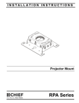
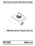
INSTALLATION INSTRUCTIONS
Projector Mount
Spanish Product Description
German Product Description
Portuguese Product Description
Italian Product Description
Dutch Product Description
French Product Description
RPA Series
RPA Series
Installation Instructions
DISCLAIMER
Milestone AV Technologies and its affiliated corporations and
subsidiaries (collectively "Milestone"), intend to make this
manual accurate and complete. However, Milestone makes no
claim that the information contained herein covers all details,
conditions or variations, nor does it provide for every possible
contingency in connection with the installation or use of this
product. The information contained in this document is subject
to change without notice or obligation of any kind. Milestone
makes no representation of warranty, expressed or implied,
regarding the information contained herein. Milestone assumes
no responsibility for accuracy, completeness or sufficiency of
the information contained in this document.
Chief® is a registered trademark of Milestone AV Technologies.
All rights reserved.
IMPORTANT SAFETY INSTRUCTIONS
WARNING: Exceeding the weight capacity can result in
serious personal injury or damage to equipment! It is the
installer’s responsibility to make sure the combined weight of
all components attached to the RPA does not exceed 50 lbs
(22.7 kg).
•
The weight capacity of the RPA may be LIMITED to the
lowest weight capacity of any other components
located between the RPA and the supporting structure!
WARNING: Use this mounting system only for its intended
use as described in these instructions. Do not use
attachments not recommended by the manufacturer.
WARNING: Never operate this mounting system if it is
damaged. Return the mounting system to a service center for
examination and repair.
WARNING: A WARNING alerts you to the possibility of
serious injury or death if you do not follow the instructions.
WARNING: Do not use this product outdoors.
IMPORTANT ! : The RPA mounts are designed to be:
CAUTION: A CAUTION alerts you to the possibility of
damage or destruction of equipment if you do not follow the
corresponding instructions.
•
WARNING: Failure to read, thoroughly understand, and
•
follow all instructions can result in serious personal injury,
damage to equipment, or voiding of factory warranty! It is the
installer’s responsibility to make sure all components are
properly assembled and installed using the instructions
provided.
WARNING: Failure to provide adequate structural strength
for this component can result in serious personal injury or
damage to equipment! It is the installer’s responsibility to
make sure the structure to which this component is attached
can support five times the combined weight of all equipment.
Reinforce the structure as required before installing the
component.
•
mounted to a 1-1/2" NPT or NPSM following ANSI/
ASME B1.20.1 (Schedule 40, 0.154" minimum
thickness steel or aluminum - ASTM B221) threaded
extension column (not included); or
mounted to a double 2" x 4" wood joist with a maximum
drywall covering of 5/8"; or
suspended from four 1/4-20 Grade ASTM A307 or
better threaded rods (not included) which are secured
to unistrut by 1/4-20 Grade 2 or better channel nuts (not
included), or to angle or channel assembly overhead
structural members (trusses or I-beams) by 1/4-20
Grade 2 or better jam nuts (not included).
NOTE: RPA Series may be used with UL Listed models
WM210S, WM220S, WM230S, WM240S, WM210SI,
WM220SI, WM230SI and WM240SI (not included).
--SAVE THESE INSTRUCTIONS--
DIMENSIONS
3.75
BOLT CIRCLE
1 ½" NPT
3.50
2.25
1.25
5.50
3.25
STUDS ON SLB CENTER
IN THESE SLOTS
4.50
.75
ACCESS HOLE
2.75
5.50
4.38
5.02
1.75
3.10
2.77
NOTE: CUSTOM INTERFACE BRACKET
NOT SHOWN. THE CUSTOM INTERFACE
BRACKET NEEDED FOR YOUR PROJECTOR
WILL ADD DEPTH TO INTALLATION AND
WILL AFFECT LOCATION OF PROJECTOR
ON MOUNT.
SEE SLB-XXXX DRAWING ALSO.
DIMENSIONS: INCHES
2
Installation Instructions
RPA Series
LEGEND
Tighten Fastener
Adjust
Apretar elemento de fijación
Ajustar
Befestigungsteil festziehen
Einstellen
Apertar fixador
Ajustar
Serrare il fissaggio
Regolare
Bevestiging vastdraaien
Afstellen
Serrez les fixations
Ajuster
Loosen Fastener
Security Wrench
Aflojar elemento de fijación
Llave de seguridad
Befestigungsteil lösen
Sicherheitsschlüssel
Desapertar fixador
Chave de segurança
Allentare il fissaggio
Chiave di sicurezza
Bevestiging losdraaien
Veiligheidssleutel
Desserrez les fixations
Clé de sécurité
Phillips Screwdriver
Hex-Head Wrench
Destornillador Phillips
Llave de cabeza hexagonal
Kreuzschlitzschraubendreher
Sechskantschlüssel
Chave de fendas Phillips
Chave de cabeça sextavada
Cacciavite a stella
Chiave esagonale
Kruiskopschroevendraaier
Zeskantsleutel
Tournevis à pointe cruciforme
Clé à tête hexagonale
Open-Ended Wrench
Socket Wrench
Llave de boca
Clé à douilles
Gabelschlüssel
Steckschlüssel
Chave de bocas
Chave de caixa
Chiave a punte aperte
Chiave a brugola
Steeksleutel
Dopsleutel
Clé à fourche
Clé à douilles
TOOLS REQUIRED FOR INSTALLATION / PARTS
Hardware required - not included
(dependent on installation method)
5/32"
1.
7/16"
2.
1/8" (wood)
3.
7/16"
Install to threaded extension column
•
1-1/2" NPT or NPSM following ANSI/ASME
B1.20.1 (Schedule 40, 0.154" minimum
thickness steel or aluminum - ASTM B221)
threaded extension column (not included)
A (1)
[RPA]
Install to wood ceiling joists (Qty. of 4 each)
•
1/4" x 2" (minimum length) Grade 2 lag bolts
•
1/4" Grade 2 nuts
•
1/4" Grade 2 washers
Install to threaded rod
•
•
•
•
1/4-20 steel threaded rods (Qty. 4)
1/4-20 Grade 2 channel nuts (Qty. 4)
1/4-20 Grade 2 jam nuts (Qty. 8)
1/4" Grade 2 washers (Qty. 8)
B (1)
[Example of SLB bracket]
3
RPA Series
Installation Instructions
PREPARATION
Locate Mounting Site
1
WARNING: IMPROPER INSTALLATION MAY LEAD TO
Threaded extension
column (not included)
PROJECTOR MOUNT FALLING CAUSING SEVERE
PERSONAL INJURY OR DAMAGE TO EQUIPMENT! It is
the installers responsibility to make certain the structure to
which the projector mount is being mounted is capable of
supporting five times the weight of the projector mount and all
attached equipment. Reinforce the structure as required
before installing the projector mount.
1.
Determine required position of the RPA projector mount.
2.
Determine required distance of the projector mount from the
screen using the lens-to-screen distance information.
2
4
(A)
x1
NOTE: Proceed to Installing to 1-1/2" Threaded Extension
Column, Installing to Wood Framework (Joists), or
Installing to Threaded Rod section, as appropriate.
INSTALLATION
Installing to 1-1/2" Threaded Extension Column
1.
2.
3.
Install 1-1/2" NPT or NPSM following ANSI/ASME B1.20.1
(Schedule 40, 0.154" minimum thickness steel or aluminum
- ASTM B221) threaded extension column (not included)
into threaded collar until tight, with a minimum of four
threads engaged.
Thread RPA projector mount (A) onto the threaded
extension column (not included) until hand tight, with a
minimum of four threads engaged.
Turn RPA clockwise or counter-clockwise until front of
mount is facing target.
Figure 1
5.
Proceed to Installing Projector with Interface Bracket
section.
Installing to Wood Framework (Joists)
1.
Using the RPA as a guide, mark four mounting hole
locations. (See Figure 2)
2.
Drill four 1/8" x 1-1/2" deep (minimum depth) pilot holes.
(See Figure 2)
IMPORTANT ! : When RPA is properly positioned, the
set screw access hole should be pointing directly at
target, or 180° AWAY from target.
4.
1
Secure RPA to pipe by turning set screw until tight. (See
Figure 1)
x4
2
CAUTION: DO NOT OVERTIGHTEN! Overtightening of set
screw can damage threads on pipe.
(example only)
Figure 2
3.
4
Align four mounting holes in RPA with four pilot holes.
Installation Instructions
IMPORTANT ! : When RPA is properly positioned, the
set screw access hole should be pointing directly at
target, or 180° AWAY from target.
4.
RPA Series
4.
Secure the threaded rods to the RPA with one 1/4-20 jam
nut (not included) and one 1/4" washer (not included) on
each threaded rod. (See Figure 4)
Secure RPA to structure using four 1/4" x 2" minimum length
lag bolts (not included) and four 1/4" flat washers (not
included). (See Figure 3)
1 Secure to unistrut
using channel nuts
(not included).
Secure to angle or
channel assembly
using jam nuts
(not included).
NOTE: If the wood framework structure allows, the hardware
may be installed from above the RPA projector mount.
Threaded
rods
3
3
(A)
4
x4
Secure with jam
4 nuts and washers
(not included)
Figure 4
Figure 3
5.
5.
Proceed to Installing Projector with Interface Bracket
section.
Installing to Threaded Rod
NOTE: The RPA projector mount may be suspended from four
1/4-20 steel threaded rods (not included) which are
secured to unistrut by 1/4-20 Grade 2 or better channel
nuts (not included), or to angle or channel assembly
overhead structural members (trusses or I-beams) by
1/4-20 Grade 2 or better jam nuts (not included).
Threaded rods must have 16 threads per square inch.
1.
Secure one end of each of the four threaded rods (not
included) to the structural member.
2.
Install one 1/4-20 jam nut (not included) and one 1/4"
washer (not included) onto each threaded rod.
3.
Install RPA onto threaded rods, inserting the rods into the
four slots on top of the RPA.
Proceed to Installing Projector with Interface Bracket
section.
PROJECTOR INSTALLATION
IMPORTANT ! : Model RPA uses optional Chief "SLB"
Series interface brackets. See Parts drawing.
1.
Attach projector to interface bracket (B) using installation
instructions and hardware included with the interface
bracket.
NOTE: Security screws can be substituted when mounting
interface bracket to projector by using the hardware
and installation instructions in the All-Points Security
Kit (included with interface bracket).
NOTE: Hole in the RPA allows socket wrench access without
unit disassembly.
5
RPA Series
Installation Instructions
Installing Projector with Interface Bracket
(Mounting structure not shown for clarity)
1.
Orient projector with interface bracket.
2.
Loosen (but do not remove) thumb nuts on the interface
bracket. (See Figure 5)
3.
Raise projector with attached interface bracket to RPA
projector mount (A). (See Figure 5)
6
5
x4
(Mounting structure not shown for clarity)
(A)
5
2
x4
Locating slots
3
Figure 6
7.
Figure 5
4.
Align the thumb nuts on the interface bracket with the
locating slots on the RPA projector mount. (See Figure 6)
5.
Slide the interface bracket with attached projector to the
limit of the locating slots. (See Figure 6)
WARNING: IMPROPER INSTALLATION CAN LEAD TO
PROJECTOR FALLING RESULTING IN SERIOUS
PERSONAL INJURY OR DAMAGE TO EQUIPMENT. Make
certain mounting slots in RPA projector mount base slide
under thumb screws and that screws are seated in the back
of locating slots.
6.
6
Tighten thumb nuts to secure projector in place.
Route all cables as required.
Installation Instructions
RPA Series
ADJUSTMENTS
4
The RPA projector mount can be adjusted for pitch (vertical
elevation), roll (horizontal tilt), and yaw (rotation).
5
6
x4
WARNING: OVER-LOOSENING OR REMOVAL OF
HARDWARE MAY RESULT IN PERSONAL INJURY OR
SERIOUS DAMAGE TO EQUIPMENT! RPA projector mount
and hardware is to be loosened only enough to allow for
necessary movement.
5
Pitch (Vertical Elevation)
Adjust pitch using the two pitch adjustment screws located on
each end of the RPA.
1.
Loosen two pitch adjustment screws located on each end of
the RPA.
2.
Adjust projector angle to desired pitch. (See Figure 7)
3.
Tighten two pitch adjustment screws located on each end of
the RPA.
1
2
Yaw (Rotation)
Adjust yaw by threading or unthreading the RPA projector
mount on the threaded extension column (not included).
3
x4
2
Figure 8
7.
Loosen set screw. (See Figure 9)
WARNING: IMPROPER ADJUSTMENT CAN LEAD TO
PROJECTOR FALLING RESULTING IN SERIOUS
PERSONAL INJURY OR DAMAGE TO EQUIPMENT. Do
NOT unthread RPA to the end of pipe threads!
2
8.
Adjust projector by turning RPA projector mount on the
extension column to the desired yaw position.
9.
Tighten set screw.
7
8
9
Figure 7
8
Roll (Horizontal Tilt)
Adjust roll using the four roll adjustment screws, two on front
and two on the back of the RPA.
4.
Loosen two roll adjustment screws on each side of the RPA.
5.
Adjust projector to desired position. (See Figure 8)
6.
Tighten two roll adjustment screws on each side of the RPA.
Figure 9
7
RPA Series
Installation Instructions
USA/International
Europe
Chief Manufacturing, a products division
of Milestone AV Technologies
8800-002417 Rev00
2013 Milestone AV Technologies, a
Duchossois Group Company
www.chiefmfg.com
06/13
Asia Pacific
A
P
F
A
P
F
A
6436 City West Parkway, Eden Prairie, MN 55344
800.582.6480 / 952.225.6000
877.894.6918 / 952.894.6918
Franklinstraat 14, 6003 DK Weert, Netherlands
+31 (0) 495 580 852
+31 (0) 495 580 845
Office No. 1 on 12/F, Shatin Galleria
18-24 Shan Mei Street
Fotan, Shatin, Hong Kong
P 852 2145 4099
F 852 2145 4477