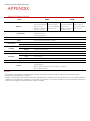
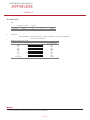
1
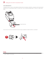
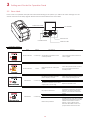
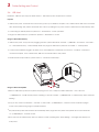
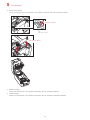
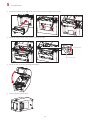
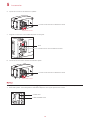
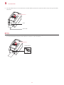
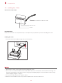
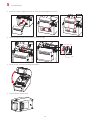
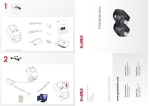
RT200i/RT230i BARCODE PRINTER USER MANUAL User Manual : RT200i series Version : Rev. 1.4 Issue Date : 2012.10.25 P/N : 920-014511-00 RT200i/RT230i USER MANUAL FCC COMPLIANCE STATEMENT FOR AMERICAN USERS This equipment has been tested and found to comply with the limits for a CLASS A digital device, pursuant to Part 15 of the FCC Rules. These limits are designed to provide reasonable protection against harmful interference when the equipment is operated in a commercial environment. This equipment generates, uses, and can radiate radio frequency energy and, if not installed and used in accordance with the instructions, may cause harmful interference to radio communications. Operation of this equipment in a residential area is likely to cause harmful interference in which case the user will be required to correct the interference at own expense. EMS AND EMI COMPLIANCE STATEMENT FOR EUROPEAN USERS This equipment has been tested and passed with the requirements relating to electromagnetic compatibility based on the standards EN 55022:1998+A1:2000+A2:2003, CISPR 22, Class A EN 55024: 1998+A1: 2001+A2: 2003, IEC 61000-4 Series EN 61000-3-2/2000&EN 61000-3-3/1995. The equipment also tested and passed in accordance with the European Standard EN55022 for the both Radiated and Conducted emissions limits. RT200i SERIES TO WHICH THIS DECLARATION RELATES IS IN CONFORMITY WITH THE FOLLOWING STANDARDS EN55022: 1998, CLSPR 22, Class A/EN55024: 1998/IEC 61000-4 Serial/EN61000-3-2: 2000/EN 6100-3-3: 1995/CFR 47, Part 15/CISPR 22 3rd Edition: 1997, Class A/ANSI C63.4: 2001/CNS 13438/IEC60950-1: 2005 (EN 60950-1: 2006+A11: 2009)/ GB4943: 2001/ GB9254: 1998/GB17625.1: 2003/EN60950-1: 2001 Caution **** Danger of explosion if battery is incorrectly replaced. Replace only with the equivalent type recommended by the manufacturer. **** Dispose of used batteries according to the manufacturer’s instructions. **** Only use with designated power supply adapter model. **** Changes or modifications not expressly approved by the party responsible for compliance could void the user's authority to operate the equipment. Declaration RT200i/RT230i USER MANUAL SAFETY INSTRUCTIONS Please read the following instructions carefully. 1. Keep the equipment away from humidity. 2. Before you connect the equipment to the power outlet, please check the voltage of the power source. 3. Make sure the printer is off before plugging the power connector into the power jack. 4. It is recommended that you connect the printer to a surge protector to prevent possible transient overvoltage damage. 5. Be careful not to get liquid on the equipment to avoid electrical shock. 6. For safety and warranty reasons, ONLY qualified service personnel should open the equipment. 7. Do not repair or adjust energized equipment under any circumstances. Safety instructions RT200i/RT230i USER MANUAL CONTENTS 1 Barcode Printer 001 1.1 Box Content 001 1.2 Getting to Know Your Printer 002 2 Printer Setup 005 2.1 Open the Printer 005 2.2 Loading the Ribbon 006 2.3 Loading the Label Roll Module 010 2.4 Connecting the Printer to the Host Computer 013 2.5 Installing Printer Driver and QLabel with Super 015 Wizard CD 3 Setting and Control for Operation Panel 020 3.1 Operation Panel 020 3.2 LCD Interface Introduction 021 3.3 LCD Interface Function 026 3.4 Label Calibration and Self Test 030 3.5 Error Alerts 032 3.6 USB Host 034 4 NetSetting for Ethernet 036 4.1 Installing the NetSetting Software 036 4.2 The Interface of NetSetting 037 5 Accessories 044 5.1 Preparation Steps 044 5.2 Installing the Label Dispenser 046 5.3 Installing the Cutter 052 6 Maintenance and Adjustment 056 6.1 Cleaning the Print Head 056 6.2 Troubleshooting 057 Appendix Product Specifications Interface File Manipulation When Using USB Stick Contents 1 Barcode Printer 1.1 Box Content Please check that all of the following items are included with your printer. RT200i/RT230i Barcode Printer Label Stock USB Cable Ribbon Module Power Adapter Empty Ribbon Core Power Cord Ribbon AC Adapter CD RT200i/RT230i Quick Guide Including GoLabel software and RT200i/RT230i user manual. RT200i RT200/ Series * Package content may vary per region. 001 1 Barcode Printer 1.2 Getting to Know Your Printer Device Overview Front View OPERATION PANEL LCD SCREEN FEED BUTTON DIRECTION KEY POWER BUTTON FRONT COVER COVER RELEASE CATCHES Pull catches for opening the printer cover Rear View FAN-FOLD LABEL INSERT Feed slot for continuous labels USB HOST ETHERNET PORT CALIBRATION BUTTON SERIAL PORT USB PORT POWER JACK 002 1 Barcode Printer Bottom View COVER OF THE MODULE CONNECTION JACKS **** Cut-outs are not intended for wall-mount use. 003 1 Barcode Printer The Internal View of Printer LABEL SUPPLY MODULE PAPER PRESS BAR TOP COVER LABEL SUPPLY HUB RELEASE CATCH RELEASE CATCH Release catch for closing the printer cover Release catch for opening the label supply hub LABEL SENSOR MODULE LABEL GUIDES PLATEN MODULE LABEL SENSOR GUIDE TRACK PLATEN PLATEN LOCKERS The Printing Mechanism RIBBON REWIND MECHANISM RIBBON REWIND WHEEL HOLDER OF RIBBON REWIND CORE RIBBON SUPPLY MECHANISM HOLDER OF RIBBON SUPPLY CORE RIBBON SUPPLY WHEEL PRINT HEAD 004 2 Printer Setup 2.1 Open the Printer Open the Printer Cover and the Printing Mechanism Place the printer on a flat surface. Open the printer cover by pulling the release catches on both sides of the printer and lift the cover. Pull the catches toward the direction Pull the catches toward the direction COVER RELEASE CATCHES Pull the catches for opening the printer cover Lift the printer cover backward The printing mechanism is lifted up with the printer cover 005 2 Printer Setup 2.2 Loading the Ribbon A New Ribbon Module Installation A NEW RIBBON 1. EMPTY RIBBON CORE Attach the ribbon to the empty ribbon core with the adhesive strip at the end of the ribbon. Notch on left side Stick on empty ribbon core 2. Wind the ribbon around the empty ribbon core for 2 to 3 circles. Wind the ribbon around the core 3. A ribbon module is assembled as below. A NEW RIBBON MODULE RIBBON SUPPLY RIBBON REWIND 006 2 Printer Setup Load the Ribbon on the Printer For Ribbon Supply Module RIBBON SUPPLY MODULE 1. Place the right-hand side of ribbon first. Push the ribbon to tighten the spring of the holder Right side SPRING OF HOLDER Align the ribbon core to the holder 2. Then place the left-hand side of the ribbon. Align the notch of the ribbon core to the spoke Left side NOTCH OF RIBBON CORE SPOKE 007 2 3. Printer Setup The ribbon supply module loading is completed. Load the Ribbon on the Printer For Ribbon Rewind Module RIBBON REWIND MODULE 1. Pass the ribbon to round the print head. Move the empty ribbon core upward to ribbon rewind mechanism 008 2 2. Printer Setup Place the right-hand side of empty ribbon core first. Right side Align the empty ribbon core to the holder Push the empty ribbon core to tighten the spring of the holder SPRING OF HOLDER 3. Then place the left-hand side of the empty ribbon core. Turn the ribbon wheel to align the notch of empty ribbon core to the spoke. Left side Rotate backward Align the notch of empty ribbon core to the spoke NOTCH OF RIBBON CORE SPOKE 4. Turn the ribbon rewind wheel to tighten the ribbon until it has no wrinkles. The ribbon loading is completed once the ribbon supply module and ribbon rewind module are assembled correctly. Rotate backward RIBBON REWIND WHEEL 009 2 Printer Setup 2.3 Loading the Label Roll Module A New Label Supply Module Loading LABEL STOCK LABEL SUPPLY HUB 1. Unlock the release catch to lift the label supply hub. 1 Push rightward 2 Lift the label supply hub upward 2. Place the label stock on the label supply hub. Place on the label supply hub 010 2 3. Printer Setup Push the label supply module downward and close the release catch. Push downward to fix the module 4. A new label supply module is completed. Loading the Label Roll Module on the Printer 1. Feed the Label through the label guides and adjust the label guides to the label width. The label guides will help to prevent the label swaying. Through the label guides Adjust the label guides 011 2 2. Printer Setup Unlock the release catch to close the printer cover. 2 1 Close the printer cover 3. Push the release catch Press the FEED key and make sure the label is fed smoothly. The label loading is completed now. **** Please keeps the rack gear clean to ensure the smoothness of label holder. 012 2 Printer Setup 2.4 Connecting the Printer to the Host Computer 1. Please make sure that the printer is switched off. 2. Connect the power cord to the AC adapter. POWER CORD AC ADAPTER Connect the jack of the power adapter to the printer and connect the plug of the power adapter to the socket of the wall. RT200i/RT230i BARCODE PRINTER POWER ADAPTER JACK SLOT THE WALL PLUG 013 SOCKET 2 3. Printer Setup Connect the USB/serial cable to the printer and host computer. RT200i/RT230i BARCODE PRINTER USB PORT USB CABLE PLUG PLUG PC 4. Pressing the POWER button. The LCD screen should now lights up. Pressing the POWER button OPERATION PANEL LCD SCREEN POWER BUTTON 014 2 Printer Setup 2.5 Installing Printer Driver and GoLabel with Super Wizard CD 1. Insert the Super Wizard CD in the CD/DVD drive of the host computer and the program should pop up automatically. You will see the Welcome screen first. On the Welcome screen, choose “Standard Installation”. 2. The wizard will then ask you to make sure your USB and power cables are connected and that the power is turned on. Make sure that is done and then click “Next”. 3. The next screen you will see is, “Install the GoLabel Software and Windows driver”. Click “Next” to continue. ****If the Super Wizard program did not run automatically, you can either turn on the “Auto-run” setting for your CD/DVD driver or double-click the icon of CD/DVD driver to run the program. 015 2 Printer Setup 4. As the printer driver and GoLabel are installing, a screen will display a progress bar. 5. Once the installation is complete, you can start to make and print labels with GoLabel or throug the printer driver. 6. As the optional steps, you can also print a test label or register your printer during the “Standard Installation” procedure. ****If you need more resources, tools or reference documents, you can also find them on Super Wizard CD. Just click “Other Choices” on Welcome Screen to access the files. 016 2 Printer Setup Installing Printer Driver Directly From CD Folder 1. Insert the product CD in the CD/DVD drive of the host computer and open the "Seagull Drivers" folder on the CD. Select the icon for the driver file and click it to start the installation. 2. Follow the instructions on the screen. The Driver Wizard guides you through the installation procedure. Select "Install printer drivers". 3. Specify your printer model. Godex RT200i 017 2 Printer Setup 4. Specify the port used to connect the printer to the host computer. 5. Enter a printer name and assign the appropriate rights. Godex RT200i Godex RT200i 6. Once the installation is complete, a summary of the printer settings is displayed. Check whether the printer settings are correct and click "Finish" to start copying the driver files. Wait until copying is complete, then finish the installation. Godex RT200i Godex RT200i 018 2 7. Printer Setup Once the driver installation is complete, the new printer should appear in the "Printers and Faxes" folder. Godex RT200i Godex RT200i 019 3 Setting and Control for Operation Panel 3.1 Operation Panel Operation Panel Introduction OPERATION PANEL LCD SCREEN POWER BUTTON FEED BUTTON DIRECTION KEY POWER Button Press the POWER button to turn on the printer, and the START UP SCREEN appears. The printer is on “ready to print” status, the LCD screen should display the message “READY“ on the screen. When printer is turned on, keep pressing the POWER button for 3 second will turn the printer off. FEED Button When you press the FEED button, the printer moves the label to the defined stop position. If you are using continuous labels, pressing the FEED button will move label stock until you release the button again. If you are using individual labels, pressing the FEED button will move only one label. If the label does not stop at the correct position, you need to run the auto-detection function on the label stock, please see Section 3.4 Label Calibration and Self Test. 020 3 Setting and Control for Operation Panel 3.2 LCD Interface Introduction Getting Started Press the POWER button to turn on the printer, and the START UP SCREEN appears. Power on If the printer is on “ready to print” status, the LCD screen should display the message “Ready“ on the screen. Please keep pressing button and wait for the timer to be filled, then the LCD interface will enter into the MAIN PAGE for SETTING MODE. You can make various setting functions in SETTING MODE. Enter Main page 021 3 Setting and Control for Operation Panel Operations on Setting Page On MAIN PAGE, press or button to move the cursor and select the functions. Select a designated function and press FEED button, you will enter the SETTING PAGES for the function. Select or Enter On SETTING PAGES, press or button to select the setting items. Select a designated function and press FEED button, you will enter the SETTING VALUE PAGES for the function. Select or Enter 022 3 Setting and Control for Operation Panel On SETTING VALUE PAGES, press or button to change the setting values. Select or Press FEED button will apply the setting value you just selected, and the red tick will appear to mark the value. Apply **** The blue arrow indicates the value you are selected. **** The red tick indicates that the selected value is applied now. 023 3 Setting and Control for Operation Panel Exit from Current Page to Ready Status The icon on top-left corner displays the capture of upper level screen and also guides you back to upper level with left or up arrow. NAVIGATION ICON On SETTING VALUE PAGES, press button will go back to the upper level screen. Back to the Setting page On SETTING PAGES, press button will go back to the MAIN PAGE screen. Back to the Main page 024 3 Setting and Control for Operation Panel On MAIN PAGE, select the “EXIT” icon and press the FEED button to exit from SETTING MODE and the printer goes back to READY status. EXIT from Setting Mode or Back to the Ready status 025 3 Setting and Control for Operation Panel 3.3 LCD Interface Function Main Page Printer Setting Setting items for printer, ex. Printing speed, darkness. Also includes a Printing Wizard for your ease of printing. Setting items for printing label, ex. Rotation, Printing position offset. Label Setting Option modules and connection port settings. Device Self-Diagnose functions for printer, ex. TPH testing, self-test page printing. Analysis Exit from Setting Mode. Exit 026 3 Setting and Control for Operation Panel Setting Items in Setting Mode English German 繁體中文 简体中文 2-5 or 7 0-19 Label with Gaps Label with Marks Continuous Direct Thermal Thermat Transfer 0-40 0-19 2-5 or 7 LCD Language Printer Setting Speed Darkness Wizard Media Type Printer Mode Tear-off Position Darkness Speed Media Detection Sensor Media Type Direct Thermal Thermat Transfer 0-40 Apply Cancel 850 852 437 860 863 865 857 861 862 855 866 737 851 869 Win 1252 Win 1250 Win 1251 Win 1253 Win 1254 Win 1255 Win 1257 Printing Mode Tear-off Position Top of Form Setting Codepage 0° 90° 180° 270° -100 - 100 -100 - 100 -100 - 100 001 Form Name 002 Form Name Rotation Label Setting Horizental Offset Vertical Offset Start Offset Recall Label 027 Auto Select See-Through Reflective Label with Gaps Label with Marks Continuous 3 Setting and Control for Operation Panel Buzzer Device Optional Setting Option Pre-Printing Baud Rate Serial Port Setting Parity Data bits Stop bits RTC Setting Clock Display RTC Setting Calibration Self-test Analysis TPH Testing Reset to Default Label Format Graphic Clear Memory Bitmap Fonts True Type Fonts Asian Fonts ALL Exit Exit 028 Apply Cancel None Cutter Label Dispensor Applicator Apply Cancel 4800 bps 9600 bps 19200 bps 38400 bps 57600 bps 115200 bps Non Odd Even 7 bits 8 bits 1 bits 2 bits Apply Cancel YYYY/MM/DD HH:MM:SS Apply Cancel Apply Cancel Apply Cancel Apply Cancel Apply Cancel Apply Cancel Apply Cancel Apply Cancel Apply Cancel Apply Cancel 3 Setting and Control for Operation Panel Status of LCD Interface When printer is on standby status (ready to print), the LCD interface will display “Ready” on screen. You can only print on this “Ready“ status. If there is any printers error, the LCD screen will display the error screen to show the type of error. You can fix the error according the notice. WARNING ICON ERROR ICON ERROR DESCRIPTION Icon Definition To upper level To upper level Lock Unlock Scroll the value Appears on the NAVIGATION ICON of Setting Pages. It guides you back to upper level by pressing “LEFT“ key. Appears on the NAVIGATION ICON of Setting Value Pages. It guides you back to upper level by pressing “UP“ key. On Setting Value pages, press “RIGTH“ key to lock the value for preventing unexpected change. For locked value, press “RIGHT” key again to unlock the value. On Setting Value pages, press “UP“ or “DOWN“ key to scroll the values for your selection. 029 3 Setting and Control for Operation Panel 3.4 Label Calibration and Self Test Label Calibration The printer can automatically detect and store label height. That means the host computer does not need to transmit the label height to the printer. Self Test Self-test function lets you check whether the printer is functioning normally. Here is how you run the label size calibration and self test. 1. Check that the label stock is loaded correctly. 2. Turn off the printer. 3. Turn the printer on again, keeping the FEED button pressed. The printer will now measure the label stock and store the label height. 4. Once the printer has successfully measured the label stock, it will print a self-test label. The contents of a self-test printout are listed below. Model & Version USB ID setting Serial port setting MAC address of Ethernet port IP protocol setting IP address of Ethernet port RT200i:GX.XXX USB S/N:12345678 Serial port:96,N,8,1 MAC Addr:xx-xx-xx-xx-xx-xx DHCP Enable IP xxx.xxx.xxx.xxx Gateway setting Gateway xxx.xxx.xxx.xxx Netmask setting Sub-Mask xxx.xxx.xxx.xxx ################################## Number of DRAM installed 1 DRAM installed Image buffer size Image buffer size:1500 KB Number of forms 0000 FORM(S) IN MEMORY Number of graphics Number of fonts 0000 GRAPHIC(S) IN MEMORY 000 FONT(S) IN MEMORY Number of Asian fonts 000 ASIAN FONT(S) IN MEMORY Number of Databases 000 DATABASE(S) IN MEMORY Number of Scalable fonts Free memory size Speed, Density, Ref. Point, Print direction 000 TTF(S) IN MEMORY 4073 KB FREE MEMORY ^S4 ^H8 ^R000 ~R200 Label width, Form length, Stop position ^W102 ^Q100,3 ^E18 Cutter, Label Dispenser, Mode Option:^D0 ^O0 ^AD Sensor Setting Code Page Printer is on factory default Reflective AD:1.96 2.84 2.49[0.88_23] Code Page:850 Default state=Yes 030 3 Setting and Control for Operation Panel Label Calibration Button A hardware button to make a Label Calibration while printer encountering ‘’Media Error’’ during the cases when first-time printer start up or change label or ribbon to another type, such as change using gap label to continuous or black mark labels. CALIBRATION BUTTON Press Press C-button for 2 seconds, it will make an auto-sensing to calibrate the label and ribbon’s parameters. Press ****Press C-button is equivalent to the auto-sensing command ‘’~S,SENSOR’’ that will cancel on-printing-job and make the Label Calibration immediately. 031 3 Setting and Control for Operation Panel 3.5 Error Alerts In the event of a problem that prevents normal functioning of the printer, you will see an error message on LCD screen and hear some beep signals. Please refer to below table for the error alerts. OPERATION PANEL LCD SCREEN FEED BUTTON POWER BUTTON Operation Panel Status DIRECTION KEY Type Beeps Print Head Error 2 x 4 beeps The printing mechanism is not correctly closed. Open the print mechanism and close it again. Print Head Error None High temperature at the print head. Once the print head has cooled down, the printer switches to standby mode. No ribbon is installed and the printer displays an error. Make sure that the printer is set to direct thermal printing mode. The ribbon is finished or the label supply hub is not moving. Replace the ribbon roll. No paper is detected. Make sure that the label sensor is positioned correctly. If the sensor still does not detect the paper, run the auto-detection function again. Paper is finished. Replace the label roll. Printer feed problem. Possible reasons: the print medium has become trapped around the rubber roll; the sensor cannot detect a gap or black mark between the labels; there is no paper. Please reset the sensor. Media Error Media Error Description Solution 2 x 3 beeps 2 x 2 beeps 032 3 Setting and Control for Operation Panel Operation Panel Status Type Beeps Description Solution The memory is full. The printer Delete unnecessary data or install prints the message "File System full additional memory. ". File Error Use the "~X4" command to print Unable to find file. The printer all files. Then check whether the 2 x 2 beeps prints the message "File Name not files exist and whether the names found" are correct. A file of the same name already exists. The printer prints the message "Duplicate Name". 033 Change the name of the file and try storing it again. 3 Printer Setting and Control 3.6 USB Host Definition : USB Host port supports either device:USB memory stick, keyboard or scanner. Purpose USB memory stick : It extends the user memory space up to 32GB for Graphic, Font, Label Format, DBF and Command files downloading. The printer’s Firmware also can be updating if copy new version of Firmware into USB memory stick. Connecting an USB keyboard to printer for ‘’ Standalone’’ mode operation. Plug-in an USB scanner to operate the printer in ‘’Standalone’’ mode. Usage of Extended Memory USB memory stick : It supports hot-plugging function; printer will create a Folder ‘’\LABELDIR’’ and switch ‘’User Flash’’ to ‘’ Extended Memory‘’ automatically while user plugs an USB memory stick into a GoDEX ‘’i’’ model printer. Connect the USB Stick plugged -in printer to PC via USB Device or Ethernet port and run ‘’GoLabel’’ software to download Graphic, Font, Label Format, DBF and Command files to the printer. Detail download procedures, please refer to ‘’GoLabel On-line Help’’. Usage of Firmware Update Remove USB memory stick from printer and plug-in it to a PC’s USB port; delete Firmware ‘’*.bin’’ file from ‘’\LABELDIR\FW’’ of USB memory stick if it existing; or create a Folder ‘’\LABELDIR\FW’’ to USB memory stick if it doesn’t existing. Copy a new version of Firmware ‘’xxxx.bin’’ to the Folder ‘’\LABELDIR\FW’’; and then remove USB and plug-in back to the printer that going to update Firmware. The printer will update the Firmware automatically when plug-it-into the printer and printer find-out the Firmware in ‘’\LABELDIR\FW’’ is newer version. Don’t remove the USB memory stick out while it’s under updating with ‘’Flash Writing...’’message that displays on LCD panel. 034 3 Printer Setting and Control USB Keyboard When plug-in an USB keyboard to the printer, LCD panel will display “Standalone Mode”, press the “Enter” key on keyboard and “Feed” key in the printer to entering to the dialog for “Recall Label” operation. Only the sub-dialog “Recall Label” is able operating by keyboard as follow definition: 1. Press “ESC” key to exist from “Standalone Mode” or back to previous dialog 2. Press “F1”, it will let the printer from “Ready” mode entering into “Standalone Mode” 3. Press “Enter”, “Arrow” and “Alphabetic” keys as the usual in PC that will perform the key-in function of “Recall Label” in “Standalone Mode”. Scanner When plug-in an USB scanner to the printer, LCD panel will display “Standalone Mode”, press the “Feed” key in the printer to entering the dialog of “Recall Label” operation. User performs the “Recall Label” function interactively through the LCD panel, 4 direction keys, Feed key and Scanner. Scanner is using in “standalone Mode” to scanning the “Serial Number, Variable” and Print Quantity while the printer prompts a message on LCD panel and wait for data input. ** The USB Host port on ‘’i’’ ‘’x’’ model printer is without ‘’HUB’’ function. ** The USB Memory Stick supports with ‘’FAT32’’Disk Format and up to 32GB only. The certified venders are Transcend, Apacer, Patriot, Consair and Kingston. * The download function for Graphic, Font, Label Format, DBF and Command files is operated by GoLabel of PC and must go through the a ‘’i’’ ‘’x’’ model printer itself. * On a PC, user may copy entire folder’’\LABELDIR’’ from USB memory stick to PC or vice-versa. Copy a sub-folder or individual file in ‘’\LABELDIR’’ to PC or vice-versa is not supported. 035 4 NetSetting for Ethernet 4.1 Installing the NetSetting software The NetSetting software is used to manage the network configurations when connecting the printer via Ethernet port. It is available on product CD or can be downloaded from official website. To install the NetSetting, please follow below steps. 1. Insert the product CD in the CD/DVD drive of the host computer and open the "Ethernet" folder on the CD. 2. Select the icon for the NetSetting installation file and click it to start the installation. 3. Follow the instructions on the screen. The Setup Wizard guides you through the installation procedure. 4. Specify the “Installation Folder". 5. Click ”Next” to start the installation. 6. Once the installation is completed; you will see the NetSetting icon on your desktop. 036 4 NetSetting for Ethernet 4.2 The Interface of NetSetting Click the NetSetting icon to start the program; you will see the start page as below. The start page will display the basic information of connected printer and your PC. RT200i Click the magnifier icon to search the Godex printers which are connected via Ethernet port in you network environment. Once a connected Godex printer is detected, it will be listed on the start page. There are six tabs on the top of interface which can configure different types of network settings. But for the data security reason, you need correct password to enter the configuration pages. **** The default password is “1111”, you can change the password later from the “IP Setting” tab. 037 4 NetSetting for Ethernet IP Setting The IP Setting tab can change the printer name, Port number, Gateway setting and the password for configuring the printer. You can also set the printer’s IP address ether by DHCP or by Static IP. You can press “Set” button to apply the settings and “ReGet” button to refresh the setting values. **** To fully benefit from the NetSetting software, you should be familiar with basic networking principles. Please contact your network administrator for related network setting information. 038 4 NetSetting for Ethernet Alert Path Setting NetSetting will send the alert messages to designated mail account when the error happened on printer. The alert messages are sent by SMTP (Simple Mail Transfer Protocol) or SNMP (Simple Network Management Protocol). You can set or change the configurations of SMTP and SNMP on this “Alert Path Setting” tab. You can press “Set” button to apply the settings and “ReGet” button to refresh the setting values. 039 4 NetSetting for Ethernet Alert Message Setting For the alert message notification function, you can decide which error cases need to be sent out to the operator. Moreover, the alert messages can be set to be sent by SMTP, SNMP or both. You can press “Set” button to apply the settings and “ReGet” button to refresh the setting values. 040 4 NetSetting for Ethernet Printer Configuration Set or change the configurations of connected printer. Most of key settings for the printer operation can be done by this setting page. RT200i You can press “Set” button to apply the settings and “ReGet” button to refresh the setting values. 041 4 NetSetting for Ethernet User Command The “User Command” tab provides a communication interface for operator to control the printer. Input printer commands in "Input Command" window and press “Send Command” button, the commands will be sent to the printer. For some commands that will return response message, the message will be displayed in "Output Message" window. You can press “Send Command” button to send printer commands via Ethernet port and control the printer remotely. 042 4 NetSetting for Ethernet Firmware Download On “Firmware Download” tab, the current version of printer firmware will be showed on the screen. If you need to update the printer firmware, just specify the file location of firmware file and press “Start Download Firmware” button. The printer firmware then can be updated remotely. BOOT : 1.000a1 F/W : RT200i 1.000a In addition to the firmware update, you can press “Recover To Factory Settings” button to restore the printer configurations back to factory default. 043 5 Accessories 5.1 Preparation Steps Before installing the optional modules, please make some preparations as follows. 1. Turn off the printer 2. Open the printer cover and the printing mechanism Remember to switch off the printer before installing any module. Open the printer cover by pulling the release catches on both sides of the printer and lift the cover. Please see the Section 2.1 for further information about Open The Printer. The printing mechanism is lifted up with the printer cover 3. Remove the front cover Please pull frontward to remove the front cover. Pull frontward 044 5 4. Accessories Remove the platen Lift up the release clips on both sides of the platen to release and pull upward the platen. Release the clip CLIP Pull up the platen 5. Ribbon loading Please see the Section 2.2 for further information about Loading The Ribbon. 6. Label loading Please see the Section 2.3 for further information about Loading The Label Roll Module. 045 5 Accessories 5.2 Installing the Label Dispenser The Overview of the Label Dispenser PAPER SENSOR PAPER FEED ROLLER CONNECTION CABLE OF LABEL DISPENSER COVER Preparation Steps Please see the Section 5.1 Preparation Steps to complete the preparation steps before installing the label dispenser. Installing the Label Dispenser 1. Pass the connection cable through the slot of the printer. **** A label liner thickness of 0.006 mm ± 10% and a weight of 65 g/m2 ± 6% are recommended. **** The label dispenser will take labels up to a max. width of 60 mm. **** When using the label dispenser, set the stop position (printer command ^E) to 13. 046 5 Accessories 2. Place label dispenser to align both holes of screw and then tighten the screws. 3. Place the platen back to the printer and lock the clips. Lock the clip CLIP 4. Close the top cover and printing mechanism. 5. Turn the printer upside down. 047 5 6. Accessories Open the cover on the bottom of printer. COVER OF THE MODULE CONNECTION JACKS Open the cover 7. Plug the connector fo the label dispenser to the jack. Plug JACK CONNECTOR OF THE CONNECTION CABLE 8. Close the cover of the module connection jacks. COVER OF THE MODULE CONNECTION JACKS Close the cover ****The printer must be switched off when plugging the connector, or the motherboard may be destroyed! ****There are 2 jacks : the lower jack for the label dispenser, the upper jack for the cutter. CUTTER JACK LABEL DISPENSER JACK 048 5 Accessories Loading Label Roll with the Label Dispenser Module 1. Remove the first label from the label stock. LABEL STOCK LABEL LINER Tear a label 2. THE FIRST LABEL Feed the Label stock through the label guides. Through the label guides 3. Pull the label liner through the platen and the steel of the label dispenser. LABEL LINER PLATEN STEEL ****Labels should be at least 25 mm high. 049 5 4. Accessories The feeding path of label and liner should be as shown in below graphic. LABEL LABEL LINER LABEL STOCK PLATEN ROLLER 5. Close the label dispenser and printer cover. The installation is completed now. Close the cover 050 5 6. Accessories Press the FEED button to feed the label. The label will be peeled from the liner while it passes through the label dispenser. Press the FEED button LABEL LABEL LINER **** There is a paper sensor on the Label Dispenser module. It will stop the printing if it is covered by label. Remove the last printed label and the printer will then continue to print next label. Press the FEED button PAPER SENSOR 051 5 Accessories 5.3 Installing the Cutter The Overview of the Cutter CONNECTION CABLE OF CUTTER FEED-OUT SLOT COVER Preparation Steps Please see the Section 5.1 Preparation Steps to complete the preparation steps before installing the cutter. Installing the Cutter 1. Pass the connection cable through the slot of the printer. ****Remember to switch off the printer before installing the cutter. ****Do not use to cut adhesive labels! Glue residue will be left on the cutter blade and impair its functioning. The cutter has a blade life of 1000,000 cuts when using paper weighing 120g/m², and of 500,000 cuts when using paper weighing 120g/m² - 170g/m². ****You can cut paper with a max. width of 60mm. ****With the cutter installed, set the stop position in Qlabel to 30, and the E value to 30. 052 5 Accessories 2. Place the cutter to align both holes of screw and then tighten the screws. 3. Place the platen back to the printer and lock the clips. Lock the clip CLIP 4. Close the top cover and printing mechanism. 5. Turn the printer upside down. 053 5 6. Accessories Open the cover on the bottom of printer. COVER OF THE MODULE CONNECTION JACKS Open the cover 7. Plug the connector for the cutter to the jack. Plug JACK CONNECTOR OF THE CONNECTION CABLE 8. Close the cover of the module connection jacks. COVER OF THE MODULE CONNECTION JACKS Close the cover ****The printer must be switched off, or the motherboard may be destroyed! ****There are 2 jacks : the lower jack for the label dispenser, the upper jack for the cutter. CUTTER JACK LABEL DISPENSER JACK 054 5 Accessories Installing the Label Roll Module on the Printer 1. Pass the labels through the guides and the cutter. Through the label guides Through the cutter 2. Close the top cover and printing mechanism. To finish, press the FEED button to set the label position. Close the top cover Press the FEED button ****We advise against using inside wound label stock. ****Labels should be at least 30 mm high. When using the printer with the cutter, you should set the stop position (^E) to 30. 055 6 Maintenance and Adjustment 6.1 Cleaning the Print Head Dirt on the print head or ribbon, or glue residue from the label stock may result in inadequate print quality. The printer cover must therefore always be closed during printing. Keeping dirt and dust away from the paper or labels ensures a good print quality and a longer lifespan of the print head. Cleaning Steps Here is how you clean the print head. 1. Turn off the printer. 2. Open the printer cover. 3. Remove the ribbon. 4. To remove any label residue or other dirt from the print head (see red arrow), please use a soft lint-free cloth dipped in alcohol. To clean the print head PRINT HEAD ****The print head should be cleaned once a week. ****Please make sure that there are no metal fragments or other hard particles on the soft cloth used to clean the print head. 056 6 Maintenance and Adjustment 6.2 Troubleshooting Problem The printer is switched on but the LCD screen does not light up. The LCD screen show the notice icon and printing is interrupted. Solution ♦ Check the power supply. Please see the Section 2.4 ♦ Check the software settings (driver settings) or command codes. ♦ Look for the error alert in the table in Section 3.5. Error Alerts. ♦ Check whether the print mechanism is closed correctly. Please see the Section 3.5 The label stock passes through the printer but no image is printed. ♦ Please make sure that the label stock is loaded the right way up and that it is suitable material. ♦ Choose the correct printer driver. ♦ Choose the correct label stock and a suitable printing mode. ♦ Clear the paper jam. Remove any label material left on the thermal print head and clean the print head using a soft lint-free cloth dipped in alcohol. The label stock jams during printing. Please see the Section 6.1 There is no printed image on some parts of the label. There is no printed image on part of the label or the image is blurred. The printed image is positioned incorrectly. A label is missed out during printing. ♦ Check whether any label material or ribbon is stuck to the thermal print head. ♦ Check for errors in the application software. ♦ Check whether the starting position has been set incorrectly. ♦ Check the ribbon for wrinkles. ♦ Check the thermal print head for dust or other dirt. ♦ Use the internal “~T” command to check whether the thermal print head will carry out a complete print job. ♦ Check the quality of the print medium. ♦ Check whether there is paper or dust covering the sensor. ♦ Check whether the label stock is suitable. Contact your supplier. ♦ Check the paper guide settings. ♦ Check the label height setting. ♦ Check whether there is dust covering the sensor. ♦ Run the auto-detection function. Please see the Section 3.4 ♦ The printed image is blurred. ♦ Check the darkness setting. Check the thermal print head for dust or dirt. Please see the Section 6.1 The cutter does not cut off the labels in a straight line. ♦ Check whether the label stock is positioned straight. The cutter does not cut off the labels completely. ♦ Check whether the label is more than 0.2 mm thick. When using the cutter, the labels are not fed through or cut off incorrectly. ♦ Check whether the cutter has been correctly installed. ♦ Check whether the paper guides are functioning correctly. The label dispenser is not functioning normally. ♦ Check whether there is dust on the label dispenser. ♦ Check whether the label stock is positioned correctly. **** If any problems occur that are not described here, please contact your dealer. 057 RT200i/RT230i USER MANUAL APPENDIX PRODUCT SPENIFICATIONS RT200i Model Print Method RT230i Thermal Transfer / Direct Thermal Resolution 203 dpi (8 dots/mm) 300 dpi (12 dots/mm) Print Speed 7 IPS (177 mm/s) 5 IPS (127 mm/s) Print Width 2.12” (54 mm) 2.24” (56.9 mm) Print Length Min. 0.16” (4 mm)** ; Max. 68” (1727 mm) Min. 0.16” (4 mm)** ; Max. 30” (762 mm) Processor 32 Bit RISC CPU Flash Memory SDRAM Sensor Type Width Thickness Label roll diameter Core diameter Types Ribbon roll diameter Ribbon Core diameter Continuous form, gap labels, black mark sensing, and punched hole; label length set by auto sensing or programming 0.6” (15 mm) Min. – 2.36” (60 mm) Max. 0.003” (0.06 mm) Min. - 0.008” (0.2 mm) Max. Max. 5” (127 mm) 1”, 1.5” (25.4 mm, 38.1 mm) Wax, wax/resin, resin 1.5” (38 mm) Max. 0.5” (12.7 mm) Length 360’ (110 m) Width 2.20” (56mm) – 2.32” (59mm) Printer Language EZPL, GEPL, GZPL auto switch Label design software Software 16MB SDRAM Adjustable reflective sensor (full range). Fixed transmissive sensor, central aligned Types Media 8MB Flash (4MB for user storage) Driver DLL GoLabel (for EZPL only) Windows 2000, XP, Vista, 7, Windows Server 2003 & 2008 Windows 2000, XP, Vista 6, 8, 10, 12, 14, 18, 24, 30, 16X26 and OCR A & B Resident Fonts Bitmap fonts Bitmap fonts 90°, 180°, 270° rotatable, single characters 90°, 180°, 270° rotatable Bitmap fonts 8 times expandable in horizontal and vertical directions Scalable fonts Bitmap fonts Download Fonts Asian fonts Scalable fonts 90°, 180°, 270° rotatable Bitmap fonts 90°, 180°, 270° rotatable, single characters 90°, 180°, 270° rotatable Asian fonts 90°, 180°, 270° rotatable and 8 times expandable in horizontal and vertical directions Scalable fonts 90°, 180°, 270° rotatable Code 39, Code 93, EAN 8 /13 (add on 2 & 5), UPC A/E (add on 2 & 5), I 2 of 5 & I 2 of 5 with Shipping Bearer Bars, 1-D Bar codes Barcodes Codabar, Code 128 (subset A, B, C), EAN 128, RPS 128, UCC 128, UCC/EAN-128 K-Mart, Random Weight, Post NET, ITF 14, China Postal Code, HIBC, MSI, Plessey, Telepen, FIM, GS1 DataBar 2-D Bar codes PDF417, Datamatrix code, MaxiCode, QR code, Micro PDF417, Micro QR code and Aztec code CODEPAGE 437, 850, 851, 852, 855, 857, 860, 861, 862, 863, 865, 866, 869, 737 Code Pages WINDOWS 1250, 1251, 1252, 1253, 1254, 1255, 1257 Unicode (UTF8, UTF16) Graphics Resident graphic file types are BMP and PCX, other graphic formats are downloadable from the software RT200i/RT230i USER MANUAL APPENDIX PRODUCT SPENIFICATIONS RT200 Model USB Device (B-Type) USB Device (B-Type) Serial port: RS-232 (DB-9) USB Device (B-Type) Interfaces USB Host (A-Type) RT230 Serial port: RS-232 (DB-9) USB Device (B-Type) Serial port: RS-232 (DB-9) USB Host (A-Type) Serial port:RS-232 (DB-9) IEEE 802.3 10/100Base-Tx USB Host (A-Type) IEEE 802.3 10/100Base-Tx USB Host (A-Type) Ethernet port (RJ-45) Ethernet port (RJ-45) Color TFT LCD with navigation button Control Panel Calibration button Power on/off button Real Time Clock Standard Power Environment Auto Switching 100-240VAC, 50-60Hz Operation temperature 41°F to 104°F (5°C to 40°C) Storage temperature Humidity Operation 30-85%, non-condensing. Storage 10-90%, non-condensing. Agency Approvals Dimension Weight -4°F to 122°F (-20°C to 50°C) CE(EMC), FCC Class A, CB, CCC, cUL Length 9.7” (245 mm) Height 6.9” (175 mm) Width 5.3” (136mm) 4.4 lbs (2.0Kg), excluding consumables Guillotine Cutter Options Label Dispenser External label roll holder for 10” (250 mm) O.D. label rolls External label rewinder Notice * Specifications are subject to change without notice. All company and/or product names are trademarks and/or trademarks of their respective owners. ** Minimum print height and maximum print speed specification compliance can be dependent on non-standard material variables such as label type, thickness, spacing, liner construction, etc. Godex is pleased to test non-standard materials for minimum print height and maximum print speed capability. RT200/RT230 USER MANUAL APPENDIX INTERFACE Pinout Description USB Connector Type : Pin NO. Function 1 VBUS Type B 2 D- 3 D+ 4 GND Serial Port Default settings: Baud rate 9600, no parity, 8 data bits, 1 stop bit, XON/XOFF protocol and RTS/CTS RS232 Housing(9-pin to 9-pin) DB9 Socket 1 RXD 2 TXD 3 DTR 4 GND 5 DSR 6 RTS 7 CTS 8 RI 9 Computer 1 2 3 4 5 6 7 8 9 DB9 Plug +5V, max 500mA TXD RXD N/C GND RTS CTS RTS N/C Printer ****The total current to the serial port may not exceed 500mA. Appendix