Transcript
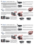
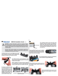
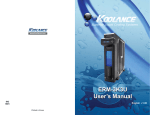
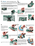
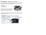
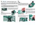
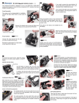
1
INS-FM17N, INS-FM19 Coolant Flow Meters v1.4
Koolance flow meters use a normallyopen magentic reed contact switch which
responds to internal impeller rotation.
The flow meters should not be directly
connected to high power outputs like
12VDC fan headers or similar controllers.
If connected directly to a custom circuit,
the intended current range is 50-100mA. A
signal graph is provided to the right:
Specifications
Flow Rate Range:
1.0 - 15 LPM (0.26 - 4 GPM)
Fluid Temperature Range:
0 - 70 ºC (32 - 158 ºF)
IMPORTANT NOTES: Be sure to install the flow meter in the correct liquid
direction! This is indicated by the arrow on the flow meter’s body. Residual air
pockets in the flow meter will not result in an accurate reading.
Frequency Adapter
An optional Koolance power adapter (ADT-FM03) can be used to multiply the flow meter impeller
signal. This allows most fan detection software, including many computer BIOS programs, to
see the flow meter tachometery as if it were a 12VDC fan RPM signal. The multiplied RPM
signal can allow 3rd-party software to log or enable an alarm event for the flow meter impeller.
With ADT-FM03, flow meter “RPMs” represent approximate coolant flow rate in mL/min, and not actual
revolutions. Be aware that 3rd-party software and BIOS programs must be configured properly if the flow
meter will be used to initiate a safety procedure.
The connections and functions for ADT-FM03 are illustrated below.
Coolant Flow Switch
(Set for 10-13mm or
6mm ID Tubing)
Flow Meter
12VDC
power supply
connection
“Fan” RPM connection
(INS-FM16 Only) LED Switch