1
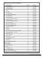
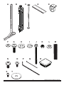
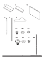
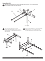
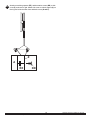
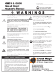
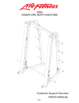
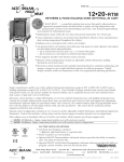
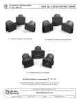
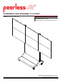
1. All dimensions:
Font = Arial Regular 8 pt
mm color = black
inch color = Pantone 201C (SMYK)
2. Captions:
Font = Century Gothic/Bold 10 pt
Color = black
3. Sub-captions:
Font = Century Gothic/Bold 8 pt
Color = black
4. Line drawings:
Color = black
Line weight = from .5 to 1 pt (visual call depending on drawing)
All arrows must be the same style
Installation and Assembly: 3 x 2 Cart
PRODUCT DATA SHEET TEMPLATE
Model: DS-VWC555-3x2
W: 7.8883" x H: 4.3737"
COMPATIBILITY FORMULA
Display width must be ≥ 39.75”
Display height must be no < 31.94”
Two display widths + hole pattern width must be <114.65”
119.21"
(3028mm)
0.63"
(16mm)
114.66"
(2912mm)
0.63"
(16mm)
31.94"
(811mm)
PLP
15.75" ADAPTER
PLATE
(400mm)
11.81"
(300mm)
12.14"
(308mm)
99.52"
(2528mm)
7.87"
5.91" (200mm)
(150mm)
13.78"
(350mm)
ADAPTER BRACKET
SIDE VIEW
± 0.63” (16mm)
Height and Depth
Adjustment
39.28"
(998mm)
FRONT VIEW
SIDE VIEW
A R C H IT E CT S S P E C I F I C AT I O N S
The Video Wall Cart shall be a Peerless model DS-VWC555-3X2 and shall be located where indicated on the plans. Assembly
and installation shall be done according to instructions provided by the manufacturer.
Maximum Load Capacity 650lbs (295kg)
1
Visit the Peerless Web Site at www.peerless-av.com
ISSUED: 04/24/2013 SHEET #: 125-9433
For customer care call 1-800-865-2112.
Parts List: 202-1526 (FINAL ASSEMBLY)
Part Description
Quantity
Part Number
A
vertical support
2
145-1543
B
adapter brackets
12
145-1711
C
horizontal support
3
145-1382
D
shelf
1
145-1361
E
5” caster
4
600-0026
F
1/4” flat washer
48
540-9440
G
M8 x 25mm phillips screw
16
520-1031
H
5/16 flat washer
16
540-9406
I
5/16 split washer
16
540-9405
J
1/4-20 x 3.5” hex head screw
48
520-1656
K
1/4-20 nylock nut
48
530-9413
L
.38 OD x .06 LG nylon washer
24
590-2233
M
18” mesh sleeve
6
600-1014
N
M8 x 16mm phillips screw
24
520-9257
O
M6 x 12mm phillips screw
24
520-1128
P
4mm allen wrench
6
560-9646
Q
cable tie
12
560-9711
R
tube cap
2
590-1289
S
M5 x 10mm socket pin screw (not used)
12
520-1164
T
#14 fender washer (not used)
24
540-1008
U
lower front cover
1
145-1505
V
lower back cover
1
145-1384
W
upper cover
2
145-1754
X
rail connection bracket
4
145-1503
Y
horizontal rail
4
145-1447
Z
side cover
2
145-1362
AA M5 x 10mm phillips screw
24
520-1233
BB flat washer
24
540-9400
CC lock washer
24
540-1035
DD decorative screw
12
520-2326
EE
spacer
4
590-1136
FF
self-drilling screw
3
520-1320
GG connection bracket
2
145-1504
HH M6 x 16mm phillips screw
36
520-9274
Before beginning, make sure you have all parts shown
2
Visit the Peerless Web Site at www.peerless-av.com
ISSUED: 04/24/2013 SHEET #: 125-9433
For customer care call 1-800-865-2112.
A
H
G
F
N
S
C
B
O
D
I
P
E
J
Q
K
L
M
R
T
3
Visit the Peerless Web Site at www.peerless-av.com
ISSUED: 04/24/2013 SHEET #: 125-9433
For customer care call 1-800-865-2112.
U
X
V
Y
W
Z
AA
BB
CC
DD
EE
FF
4
Visit the Peerless Web Site at www.peerless-av.com
GG
ISSUED: 04/24/2013 SHEET #: 125-9433
For customer care call 1-800-865-2112.
Assembling Cart
1
Attach two horizontal supports (C) to vertical support (A) using eight 1/4-20 x 3.5" hex head screws (J),
1/4" SAE washers (F) and 1/4-20 nylock nuts (K).
C
K
F
J
A
2
Attach horizontal supports (C) to second
vertical support (A) using eight 1/4-20 x 3.5" hex
head screws (J), 1/4" SAE washers (F) and 1/4-20
nylock nuts (K).
Attach horizontal support (C) to vertical supports (A)
using eight 1/4-20 x 3.5" hex head screws (J),
1/4" SAE washers (F) and 1/4-20 nylock nuts (K).
3
C
F
J
A
K
A
F
K
C
J
A
5
Visit the Peerless Web Site at www.peerless-av.com
ISSUED: 04/24/2013 SHEET #: 125-9433
For customer care call 1-800-865-2112.
4
Attach four swivel casters (E) to vertical supports (A) using sixteen M8 x 25 mm pan phillips screws (G),
split washers (I) and 5/16" SAE flat washers (H).
G
I
H
E
A
5
Attach two rail brackets (Y) together using two rail connection brackets (X) with eight M5 x 10 mm pan phillips
screws (AA), lock washers (CC), and flat washers (BB).
X
BB CC AA
Y
6
Visit the Peerless Web Site at www.peerless-av.com
ISSUED: 04/24/2013 SHEET #: 125-9433
For customer care call 1-800-865-2112.
6
Determine position of horizontal rails assemblies using the formula below.
1. Locate the position of the lower horizontal rail assemblies and attach to vertical supports (A).
2. Use display height to determine location of upper horizontal rail assemblies,
NOTE: Horizontal rail assemblies must be secured using sixteen 1/4-20 x 3.5" hex head screws (J).
X = HEIGHT OF DISPLAY
X
HORIZONTAL RAIL ASSEMBLY
DISTANCE
EQUALS
DISPLAY
HEIGHT
UPPER HORIZONTAL RAIL
DISPLAY HEIGHT
LOWER HORIZONTAL RAIL
A
7
Visit the Peerless Web Site at www.peerless-av.com
ISSUED: 04/24/2013 SHEET #: 125-9433
For customer care call 1-800-865-2112.
7
Attach two horizontal rails assemblies onto vertical supports (A) using 16 1/4-20 x 3.5" hex head screws (J), 1/4"
SAE washers (F) and 1/4-20 nylock nuts (K) as shown in detail 2. Make sure that horizontal rail
assemblies are level then tighten all 1/4-20 x 3.5" hex head screws (J). Place two tube caps (R) into tops of vertical
supports (A) as shown in detail 2.
K
Y
F
R
J
J
J
A
A
CABLE MANAGEMENT
8
DETAIL 2
NOTE: Display cables can be covered using
18" mesh sleeve (M) before securing.
Display cables can be secured to horizontal
rails assemblies using cable ties (Q) as needed
through slots in horizontal rails (Y).
Q
M
Y
A
SLOT
Y
8
Visit the Peerless Web Site at www.peerless-av.com
ISSUED: 04/24/2013 SHEET #: 125-9433
For customer care call 1-800-865-2112.
9
NOTE: Connection brackets (GG) orientation.
Place connection brackets (GG) onto rail connection brackets (X) as shown below.
X
RIGHT SIDE
GG
FRONT OF DISPLAY CART
X
LEFT SIDE
GG
FRONT OF DISPLAY CART
9
Visit the Peerless Web Site at www.peerless-av.com
ISSUED: 04/24/2013 SHEET #: 125-9433
For customer care call 1-800-865-2112.
9-1 Attach connection brackets (GG) onto rail connection brackets (X) as shown below.
Secure one connection brackets (GG) with four M5 x 10 mm phillips screws (AA), lock washers (CC), and
flat washers (BB) as shown below. Repeat step for remaining connection bracket (GG).
GG
BB
AA CC
X
FRONT
BACK
10
Visit the Peerless Web Site at www.peerless-av.com
ISSUED: 04/24/2013 SHEET #: 125-9433
For customer care call 1-800-865-2112.
10
Attach adapter brackets (B) to back of display using four M6 x 12 mm phillips screws (O) or M6 x 16 mm Phillips
screw (HH) with nylon shoulder washer (L), or four M8 x 15 mm phillips screws (N) as shown below.
Adapter Bracket Mounting Patterns
B
200 mm MIN
600 mm MAX
L
200 mm
DISPLAY
400 mm
300 mm
PLP PLATE
N or O,HH
B
11
Hook display and adapter brackets (B) onto horizontal rail assemblies as shown below.
NOTE: Start with bottom display.
NOTE: Once display is located in desired position, tighten security screws as shown in detail 4.
DISPLAY NOT SHOWN FOR CLARITY
D
B
TIGHTEN
SECURITY
SCREW
DETAIL 4
11
Visit the Peerless Web Site at www.peerless-av.com
ISSUED: 04/24/2013 SHEET #: 125-9433
For customer care call 1-800-865-2112.
12
Fasten shelf (D) onto horizontal support (C) using three self-drilling screws (FF) as shown below.
C
FF
D
12
Visit the Peerless Web Site at www.peerless-av.com
ISSUED: 04/24/2013 SHEET #: 125-9433
For customer care call 1-800-865-2112.
Adapter Bracket Adjustment
13 Use legend below to determine position of display.
NOTE: Each knob can be adjusted independently for fine tuning angle adjustments.
Turn knobs CLOCKWISE to raise display height.
Turn knobs CLOCKWISE to push out display.
Turn knobs COUNTER-CLOCKWISE to lower display height.
Turn knob COUNTER-CLOCKWISE to pull in display.
UP
DOWN
IN
OUT
KNOB
13
Visit the Peerless Web Site at www.peerless-av.com
ISSUED: 04/24/2013 SHEET #: 125-9433
For customer care call 1-800-865-2112.
Attaching Covers
14
NOTE: Position bottom front and back covers first
Position front bottom cover (U). Secure covers in place using four decorative screws (DD) as shown below.
Position back bottom cover (V). Secure covers in place using four decorative screws (DD) as shown below.
Position upper covers (W) on front and back of vertical supports (A). Secure upper covers at top (W) with
two 1/4-20 x 3.5” hex head screws (J), two 1/4” flat washer (F), and two 1/4-20 nylock nuts (K).
Secure base of covers in place using two decorative screws (DD) as shown below.
W
DD
U
J
F K
W
BACK VIEW
14
Visit the Peerless Web Site at www.peerless-av.com
V
ISSUED: 04/24/2013 SHEET #: 125-9433
For customer care call 1-800-865-2112.
15
Attach two retaining spacers (EE), and decorative screws (DD) to side
cover (Z) as shown to right. Attach side cover to vertical support (A) so
that it goes inside the lower front and back covers (U and V).
Z
A
EE
DD
15
Visit the Peerless Web Site at www.peerless-av.com
ISSUED: 04/24/2013 SHEET #: 125-9433
For customer care call 1-800-865-2112.
Peerless-AV
2300 White Oak Circle
Aurora, IL 60502
Email: [email protected]
Ph: (800) 865-2112
Fax: (800) 359-6500
www.peerless-av.com
© 2013, Peerless Industries, Inc.
16
Visit the Peerless Web Site at www.peerless-av.com
ISSUED: 04/24/2013 SHEET #: 125-9433
For customer care call 1-800-865-2112.