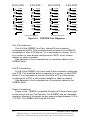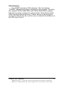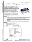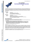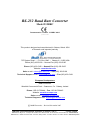
1
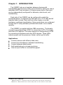
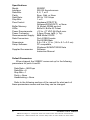
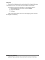
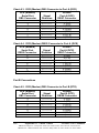
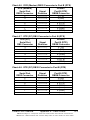
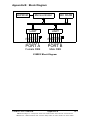
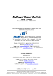
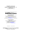
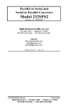
RS-232 Baud Rate Converter
Model 232BRC
Documentation Number 232BRC-0812
pn5104-r006
This product designed and manufactured in Ottawa, Illinois USA
of domestic and imported parts by
707 Dayton Road -- P.O. Box 1040 -- Ottawa, IL 61350 USA
Phone (815) 433-5100 -- General Fax (815) 433-5105
Phone (815) 433-5100 -- General Fax (815) 433-5105
Website: www.bb-elec.com
Sales e-mail: [email protected] -- Fax (815) 433-5109
Technical Support e-mail: [email protected] -- Fax (815) 433-5104
European Headquarters
B&B Electronics
Westlink Commercial Park -- Oranmore, Co. Galway, Ireland
Phone +353 91-792444 -- Fax +353 91-792445
Website: www.bb-europe.com
Sales e-mail: [email protected]
Technical Support e-mail: [email protected]
B&B Electronics – Revised November 2007
Manual Documentation Number 232BRC-0812
Cover Page
B&B Electronics Mfg Co Inc – 707 Dayton Rd - PO Box 1040 - Ottawa IL 61350 - Ph 815-433-5100 - Fax 815-433-5104 – www.bb-elec.com
B&B Electronics – Westlink Commercial Park – Oranmore, Galway, Ireland – Ph +353 91-792444 – Fax +353 91-792445 – www.bb-europe.com
TABLE OF CONTENTS
Chapter 1: INTRODUCTION .............................................. 3
Applications ........................................................................... 3
Specifications ........................................................................ 4
Default Parameters ............................................................... 4
Checklist ................................................................................ 5
Chapter 2: OPERATION ..................................................... 7
Port Configurations ................................................................ 7
Port Connections ................................................................... 9
LED Indicators ..................................................................... 11
Chapter 3: SETUP SOFTWARE ...................................... 13
Introduction .......................................................................... 13
Connection .......................................................................... 13
Software Installation ............................................................ 14
Software Uninstall ................................................................ 14
Setup Tutorial ...................................................................... 14
Main Screen ........................................................................ 15
Copying Parameters Between Units .................................... 16
Final System Installation ...................................................... 17
Default Parameters ............................................................. 17
Appendix A: Cable Charts ..............................................A-1
Port A Connections .............................................................A-1
Chart A.1. DTE (PC) DB9 to Port A (DCE) .........................A-1
Chart A.2. DTE (PC) DB25 to Port A (DCE) .......................A-1
Chart A.3. DCE (Modem) DB9 to Port A (DCE) .................A-2
Chart A.4. DCE (Modem) DB25 to Port A (DCE) ...............A-2
Port B Connections .............................................................A-2
Chart A.5. DCE (Modem) DB9 to Port B (DTE) ..................A-2
Chart A.6. DCE (Modem) DB25 to Port B (DTE) ................A-3
Chart A.7. DTE (PC) DB9 to Port B (DTE) .........................A-3
Chart A.8. DTE (PC) DB25 to Port B (DTE) .......................A-3
Appendix B: Block Diagram .......................................... B-1
Appendix C: Declaration of Conformity ....................... C-1
232BRC-0812 Manual
Table of Contents
B&B Electronics Mfg Co Inc – 707 Dayton Rd - PO Box 1040 - Ottawa IL 61350 - Ph 815-433-5100 - Fax 815-433-5104
B&B Electronics – Westlink Commercial Park – Oranmore, Galway, Ireland – Ph +353 91 792444 – Fax +353 91 792445
i
Chapter 1: INTRODUCTION
The 232BRC acts as a translator between devices with
incompatible asynchronous serial communications. Each port uses a
dedicated UART and includes a 16 kbyte receive buffer. Each port
can be independently configured for data rate, data format, and
handshaking.
Each side of the 232BRC can be configured to match the
connected device. It supports any data rate up to 115.2 kbps and all
standard data formats. Each side can either supply or accept
hardware or software handshaking. Setup parameters are configured
through the PC setup software provided and saved in non-volatile
memory.
The 232BRC is supplied with two DB9 connectors. The female
connector is configured as a DCE for connecting to PCs, Terminals,
and other DTE devices. The male connector is configured as a DTE
for connecting to Modems and other DCE devices. Three LEDs
indicate power and the presence of data in either port’s buffer.
Applications
Connect devices with different data rates.
Convert from hardware to software handshaking.
Convert between data formats.
Add handshaking to a streaming device.
Use as a port buffer to increase throughput.
232BRC-0812 Manual
B&B Electronics Mfg Co Inc – 707 Dayton Rd - PO Box 1040 - Ottawa IL 61350 - Ph 815-433-5100 - Fax 815-433-5104
B&B Electronics – Westlink Commercial Park – Oranmore, Galway, Ireland – Ph +353 91 792444 – Fax +353 91 792445
3
Specifications
Model:
Interface:
Data Bits:
Parity:
Data Rate:
Stop Bits:
Flow Control:
Buffer Memory:
LEDs:
Power Requirements:
Power Connector:
Recommended Supply:
Data Connectors:
Dimensions:
Setup Software:
Supplied Accessories:
232BRC
RS-232 Asynchronous
5, 6, 7, or 8
Even, Odd, or None
300 to 115.2 kbps
1 or 2
Hardware(RTS/CTS),
Software(XON/XOFF), or None
16 Kbytes SRAM per port
Buffer A, Buffer B, Power
+12 to +17 VDC @ 60mA max.
2.5mm Phono Jack (+ Tip)
B&B Model 232PS
Port A DB9 Female
Port B DB9 Male
5.8 x 3.6 x 1.2 in. (14.6 x 9.1 x 3.0 cm)
PC compatible,
Windows 95/98/NT/2000/Vista
Software
Instruction Manual
Default Parameters
When shipped, the 232BRC comes set up for the following
parameters for ports A and B:
Data Rate = 9600 bps
Data Bits = 8
Stop Bits = 1
Parity = None
Handshaking = None
Refer to the following sections of the manual for what each of
these parameters means and how they can be changed.
4
232BRC-0812 Manual
B&B Electronics Mfg Co Inc – 707 Dayton Rd - PO Box 1040 - Ottawa IL 61350 - Ph 815-433-5100 - Fax 815-433-5104
B&B Electronics – Westlink Commercial Park – Oranmore, Galway, Ireland – Ph +353 91 792444 – Fax +353 91 792445
Checklist
Examine the shipping carton and contents for physical damage.
If damage is found, file a claim with the shipper immediately.
The following equipment should be in the shipping carton:
1. RS-232 Baud Rate Converter model 232BRC
2. Instruction Manual
3. Software
If any of the items above are not in the shipping carton contact
the shipper immediately.
232BRC-0812 Manual
B&B Electronics Mfg Co Inc – 707 Dayton Rd - PO Box 1040 - Ottawa IL 61350 - Ph 815-433-5100 - Fax 815-433-5104
B&B Electronics – Westlink Commercial Park – Oranmore, Galway, Ireland – Ph +353 91 792444 – Fax +353 91 792445
5
6
232BRC-0812 Manual
B&B Electronics Mfg Co Inc – 707 Dayton Rd - PO Box 1040 - Ottawa IL 61350 - Ph 815-433-5100 - Fax 815-433-5104
B&B Electronics – Westlink Commercial Park – Oranmore, Galway, Ireland – Ph +353 91 792444 – Fax +353 91 792445
Chapter 2: OPERATION
Each port receives data from its connected device, buffers the
data, and sends it out the opposite port when that port’s handshaking
indicates it is ready to receive data. Each port is set to match the
requirements of its connected device through the setup software.
Unused output handshake lines are held high by the 232BRC. Pin
6 (DSR) on Port A and Pin 4 (DTR) on Port B are held in a constant
true state. This provides a constant enabled signal to connected
devices that need it, or provides a positive voltage to devices that
derive their power from these lines.
Port Configurations
The 232BRC provides a dedicated UART to ports A and B. This
allows each port to be individually configured for baud rate, number
of data bits, parity, and hardware (RTS/CTS) or software
(XON/XOFF) handshaking. Configuration parameters are set
through the setup software.
Baud rate:
Each port supports the following standard baud rates:
300
600
1200
2400
4800
9600
19.2k
38.4k
57.6k
or 115.2 kbps
In addition, non-standard baud rates between 300 and 115.2
kbps can also be set. The 232BRC uses a 1.152 MHz clock for its
base data rate, so any rate that can be evenly divided into 1.152 MHz
can be set exactly.
For example:
28.8 kbps = 1.152 MHz / 40
232BRC-0812 Manual
B&B Electronics Mfg Co Inc – 707 Dayton Rd - PO Box 1040 - Ottawa IL 61350 - Ph 815-433-5100 - Fax 815-433-5104
B&B Electronics – Westlink Commercial Park – Oranmore, Galway, Ireland – Ph +353 91 792444 – Fax +353 91 792445
7
Baud rates that are not evenly divisible into 1.152 MHz can also
be used, but the actual baud rate will vary slightly from the requested
rate. This may or may not cause data errors, depending on the
attached equipment. Most standard UARTs can accept a 5% to 10%
difference in baud rate before errors occur.
For example:
Desired Baud Rate = 20 kbps
1.152 MHz / 20 kbps = 57.6
Actual Rate = 1.152 MHz / 58 = 19.862 kbps
%error = (20 kbps – 19.862 kbps) / 20 kbps * 100
%error = 0.7%
Data bits:
Each port can be configured for Five, Six, Seven or Eight data
bits. NOTE: If the ports are set up differently, the port set for fewer
data bits cannot transmit the upper most significant bits.
Parity:
Each port can be configured for Even, Odd, or No parity. The
parity should be selected to match the connected device.
Stop Bits:
Each port can be configured for one or two stop bits. The stop
bits should be selected to match the connected device.
Flow Control:
Hardware(RTS/CTS) Handshaking:
Each port can be independently configured to hold data until
its input handshake line goes high. On Port A, pin seven (RTS)
would have to be held high by the connected device in order for the
232BRC to send data. On Port B, pin eight (CTS) needs to be held
high by the connected device for the 232BRC to send data.
Connected devices can prevent data from being sent from the
232BRC by holding their corresponding handshake lines low. This
corresponds to pin seven on Port A and pin eight on Port B. See
Appendix A for a complete table of signal directions.
8
232BRC-0812 Manual
B&B Electronics Mfg Co Inc – 707 Dayton Rd - PO Box 1040 - Ottawa IL 61350 - Ph 815-433-5100 - Fax 815-433-5104
B&B Electronics – Westlink Commercial Park – Oranmore, Galway, Ireland – Ph +353 91 792444 – Fax +353 91 792445
Software(XON/XOFF) Handshaking:
Each port can be independently configured for software
handshaking. Software handshaking is normally used in
communications links where the main data stream is one way, such
as to a printer. The main sending device is expected to hold off its
data when it receives the XOFF(13 Hex) character, and resume
sending when it receives an XON(11 Hex). The main receiving
device is expected to send the XOFF character if the buffer is full or
it otherwise needs to hold off the data.
The 232BRC can be set to emulate either the main sending
device or the receiving device. It can either supply the XON/XOFF
handshake or stop sending data with the XON/XOFF. The port would
normally be set to supply the XON/XOFF characters if it is connected
to a fast sending device. It would be set to receive the XON/XOFF
handshaking if the port is connected to the slower receiving device.
Port Connections
In order to determine the proper port connections to the
232BRC, it is necessary to have a basic understanding of the terms
DCE and DTE. RS-232 was designed, using DB-25 connectors, for
connecting a DTE (Data Terminal Equipment) device to a DCE (Data
Communication Equipment) device. Each device will have inputs on
pins that correspond to outputs on the same pins of the other device.
For example, a DTE device will transmit data out on pin 2 (on a DB25) and a DCE device will receive data in on pin 2 (on a DB-25). IBM
PCs and serial printers are DTE devices, modems are DCE devices.
Originally the RS-232 Standard specified only a 25 pin, D-sub
connector. Since then, the use of a 9 pin, D-sub supporting only a
portion of the original RS-232 signals has been used extensively,
starting with the IBM PC and migrating into other peripherals. The pin
outs for this 9 pin connector have since become the EIA/TIA 574
Standard. This standard specifies a DTE device that transmits on pin
3 and receives on pin 2, with the DCE having the opposite
configuration. Figure 2.1 shows the signal direction for 25 pin and 9
pin devices configured as a DTE and DCE.
232BRC-0812 Manual
B&B Electronics Mfg Co Inc – 707 Dayton Rd - PO Box 1040 - Ottawa IL 61350 - Ph 815-433-5100 - Fax 815-433-5104
B&B Electronics – Westlink Commercial Park – Oranmore, Galway, Ireland – Ph +353 91 792444 – Fax +353 91 792445
9
25 Pin DTE
2 (TD)
T
R
R
20 (DTR)
T
R
R
R
6 (DSR)
8 (DCD)
7 (GND)
2 (RD)
R
R
8 (CTS)
R
4 (DTR)
T
R
R
6 (DSR)
1 (DCD)
5 (GND)
T = RS-232 Transmitter
R
T
T
R
R
6 (DSR)
8 (DCD)
7 (GND)
R
T
T
7 (RTS)
8 (CTS)
T
20 (DTR)
3 (TD)
2 (RD)
T
4 (RTS)
5 (CTS)
T
9 Pin DCE
2 (TD)
3 (RD)
T
7 (RTS)
T
5 (CTS)
25 Pin DCE
3 (TD)
T
3 (RD)
4 (RTS)
T
9 Pin DTE
4 (DTR)
6 (DSR)
1 (DCD)
5 (GND)
R = RS-232 Receiver
Figure 2.1. DTE/DCE Port Diagrams
Port A Connections
Port A of the 232BRC is a 9 pin, female D-sub connector
configured as a DCE. This provides direct connection to an IBM PC
compatible or other DTE device. If it is necessary to connect Port A
to a modem or other device configured as a DCE, a null modem
adapter or cable is needed.
See Appendix A for a complete set of connection tables to the
232BRC ports.
Port B Connections
Port B of the 232BRC is a 9 pin male D-sub connector configured
as a DTE. This provides direct connection to a modem or other DCE
device. If it is necessary to connect Port B to a PC or other device
configured as a DTE, a null modem adapter or cable is needed.
See Appendix A for a complete set of connection tables to the
232BRC ports.
Power Connections
Power to the 232BRC is supplied through the 2.5mm Phono jack
on the side of the unit (Tip Positive). The 232BRC has an integrated
regulator, allowing it to operate on any supply voltage between +12 to
+17 VDC. The 232BRC will draw 60 mA max.
10
232BRC-0812 Manual
B&B Electronics Mfg Co Inc – 707 Dayton Rd - PO Box 1040 - Ottawa IL 61350 - Ph 815-433-5100 - Fax 815-433-5104
B&B Electronics – Westlink Commercial Park – Oranmore, Galway, Ireland – Ph +353 91 792444 – Fax +353 91 792445
LED Indicators
The 232BRC has three LED indicators. The first, labeled
“POWER” indicates that power is applied to the converter. The other
two, labeled “PORT A BUFFER” and “PORT B BUFFER” indicate
that data is present in that port’s receive buffer. Note that the buffer
LEDs indicate buffered data only. If either device is fast enough to
receive the data as fast as it can be sent, no data will be buffered, so
the LED may not be lit.
232BRC-0812 Manual
B&B Electronics Mfg Co Inc – 707 Dayton Rd - PO Box 1040 - Ottawa IL 61350 - Ph 815-433-5100 - Fax 815-433-5104
B&B Electronics – Westlink Commercial Park – Oranmore, Galway, Ireland – Ph +353 91 792444 – Fax +353 91 792445
11
12
232BRC-0812 Manual
B&B Electronics Mfg Co Inc – 707 Dayton Rd - PO Box 1040 - Ottawa IL 61350 - Ph 815-433-5100 - Fax 815-433-5104
B&B Electronics – Westlink Commercial Park – Oranmore, Galway, Ireland – Ph +353 91 792444 – Fax +353 91 792445
Chapter 3: SETUP SOFTWARE
Introduction
The 232BRC comes with simple setup software for configuring
the A and B ports. The software can run on any PC compatible
computer using Microsoft Windows 95, 98, NT, 2000, or Vista
operating system.
Once the ports are configured, all parameters are saved in nonvolatile memory so the 232BRC can be powered down and used
anywhere without the loss of configuration data. Configurations can
also be saved to a file for setting up more than one 232BRC to the
same configuration.
Connection
A serial (COM) port of the computer should be connected to Port
A of the 232BRC. If the computer’s serial port is a 9 pin D-sub, a
straight through connection cable is required. If the computer’s serial
port is a 25 pin D-sub, the cable should be an XT to AT adapter
cable such as B&B’s model 232CAMR, or a cable that would
normally be used with a modem. See Appendix A for a complete set
of connection tables to the 232BRC ports.
Remove the screws (4) on the bottom of the 232BRC with a
Phillips screwdriver. Remove the top cover. Install the setup jumper
marked JP1. See Figure 3.1 diagram of the PCBD. Power up the
232BRC with the setup jumper installed to put the unit in setup
mode.
NOTE: The setup software cannot recognize the connected
unit if the setup jumper is not installed or if the jumper is
installed after the 232BRC is powered up.
232BRC-0812 Manual
B&B Electronics Mfg Co Inc – 707 Dayton Rd - PO Box 1040 - Ottawa IL 61350 - Ph 815-433-5100 - Fax 815-433-5104
B&B Electronics – Westlink Commercial Park – Oranmore, Galway, Ireland – Ph +353 91 792444 – Fax +353 91 792445
13
Figure 3.1 Setup Jumper Location
Software Installation
The setup software for the 232BRC must be installed on your
hard drive before it can be run.
Software Uninstall
To remove the 232BRC setup software, follow these steps:
Select SETTINGS, CONTROL PANEL from the Windows
START menu.
Double Click ADD/REMOVE PROGRAMS
Select 232BRC SETUP from the list of installed programs.
Click the ADD/REMOVE button to remove the software
components.
Setup Tutorial
Step 1: Start the software by double clicking the
232BRC Setup icon on the desktop.
Step 2: Select the serial (COM) port that will be used to configure
the 232BRC.
Step 3: Connect the 232BRC Port A to the PC COM port selected.
Install the setup jumper, and power up the 232BRC. When Next
is clicked, the software reads the current configuration of the
connected unit and displays the Main Screen.
14
2232BRC-0812Manual
B&B Electronics Mfg Co Inc – 707 Dayton Rd - PO Box 1040 - Ottawa IL 61350 - Ph 815-433-5100 - Fax 815-433-5104
B&B Electronics – Westlink Commercial Park – Oranmore, Galway, Ireland – Ph +353 91 792444 – Fax +353 91 792445
Main Screen
All configuration of the 232BRC is done from the Main Screen.
Each port’s parameters can be individually selected and modified.
Parameters can be selected from the drop-down lists. Any baud rate
that is not in the list can be entered into the window.
232BRC-0812 Manual
B&B Electronics Mfg Co Inc – 707 Dayton Rd - PO Box 1040 - Ottawa IL 61350 - Ph 815-433-5100 - Fax 815-433-5104
B&B Electronics – Westlink Commercial Park – Oranmore, Galway, Ireland – Ph +353 91 792444 – Fax +353 91 792445
15
File Menu:
From the file menu, a configuration can be saved to disk, loaded
from a disk, or printed. This provides an easy method of
configuring multiple units with the same setup.
Read 232BRC Configuration Button:
This button will read the configuration from the connected
232BRC. The 232BRC is read upon entering the Main Screen,
so it should not have to be read again unless it is necessary to
set the parameters back after changing.
View 232BRC Settings Button:
This button will display all current port parameters of the
connected unit on one screen for review. Any changes to the
currently connected unit that have not been saved will be shown
in Red. The page can then be printed for review or for
attachment to the 232BRC.
Configure 232BRC Button:
This button will save all changes to the connected unit.
NOTE: Once changes are saved to the 232BRC they cannot be
reset automatically. Be sure to review all changes before saving
using the View Module Configuration button.
Run Self Test Button:
The 232BRC is programmed with a Self Test mode. The
microprocessor checks the UARTs, RAM, and EEPROM and
reports any errors back to the setup software. If the software
reports an error, contact B&B Technical Support.
Copying Parameters Between Units
The 232BRC setup software can save configuration data to a file
for copying of parameters. Any 232BRC’s configuration can be
copied by first reading the data from one unit, then saving to another.
Step 1: Run the setup software.
Step 2: Select serial (COM) port to be used for programming.
Step 3: If the configuration to be used is already saved to a file,
skip to Step 8.
16
2232BRC-0812Manual
B&B Electronics Mfg Co Inc – 707 Dayton Rd - PO Box 1040 - Ottawa IL 61350 - Ph 815-433-5100 - Fax 815-433-5104
B&B Electronics – Westlink Commercial Park – Oranmore, Galway, Ireland – Ph +353 91 792444 – Fax +353 91 792445
Step 4: Connect the 232BRC to be copied to the serial (COM)
port of the PC. Install the setup jumper. Apply power to the
232BRC.
Step 5: Click Next.
Step 6: Select Save As from the File menu. Save the
configuration to disk.
Step 7: Disconnect the first 232BRC from the COM port.
Step 8: Connect the destination 232BRC to the serial (COM) port
of the PC. Install the setup jumper. Apply power to the
232BRC.
Step 9: Select File/Load File and load the saved configuration.
Step 10: Click Configure 232BRC
Once the configuration file has been loaded, any number of 232BRC
modules can be set to the same parameters by connecting and
configuring each in turn.
Final System Installation
After successfully completing and testing the 232BRC
configuration, remove the setup jumper. Place the unit back in the
enclosure and re-insert the 4 Phillips screws.
NOTE: The 232BRC will not function properly until the setup
jumper is removed.
Default Parameters
When shipped, the 232BRC comes set up for the following
parameters for ports A and B:
Data Rate = 9600 bps
Data Bits = 8
Stop Bits = 1
Parity = None
Handshaking = None
232BRC-0812 Manual
B&B Electronics Mfg Co Inc – 707 Dayton Rd - PO Box 1040 - Ottawa IL 61350 - Ph 815-433-5100 - Fax 815-433-5104
B&B Electronics – Westlink Commercial Park – Oranmore, Galway, Ireland – Ph +353 91 792444 – Fax +353 91 792445
17
18
2232BRC-0812Manual
B&B Electronics Mfg Co Inc – 707 Dayton Rd - PO Box 1040 - Ottawa IL 61350 - Ph 815-433-5100 - Fax 815-433-5104
B&B Electronics – Westlink Commercial Park – Oranmore, Galway, Ireland – Ph +353 91 792444 – Fax +353 91 792445
Appendix A: Cable Charts
All charts give full pinouts. Only pins 2 & 3 are required for basic
operation. Pins 7 and 8 are needed for hardware (RTS/CTS)
handshaking. If the connected device requires DTR or DSR, these
signals are available on pins 4 and 6 respectively. See Appendix B
for a block diagram of the 232BRC.
Port A Connections
Chart A.1. DTE (PC) DB9 Connector to Port A (DCE)
DTE (PC)
Serial Port
DB9 Connector
2
3
4
5
6
7
8
Signal
Direction
<--------------------->
----------->
<--------->
<--------------------->
<-----------
232BRC
Port A (DCE)
DB9F Connector
2 (RD)
3 (TD)
4 (DTR)
5 (GND)
6 (DSR)
7 (RTS)
8 (CTS)
Chart A.2. DTE (PC) DB25 Connector to Port A (DCE)
DTE (PC)
Serial Port
DB25 Connector
2
3
4
5
6
7
20
232BRC-0812 Manual
Signal
Direction
----------->
<--------------------->
<---------<---------<--------->
----------->
232BRC
Port A (DCE)
DB9F Connector
3 (TD)
2 (RD)
7 (RTS)
8 (CTS)
6 (DSR)
5 (GND)
4 (DTR)
Appendix A: Cable Charts
B&B Electronics Mfg Co Inc – 707 Dayton Rd - PO Box 1040 - Ottawa IL 61350 - Ph 815-433-5100 - Fax 815-433-5104
B&B Electronics – Westlink Commercial Park – Oranmore, Galway, Ireland – Ph +353 91 792444 – Fax +353 91 792445
A-1
Chart A.3. DCE (Modem) DB9 Connector to Port A (DCE)
DCE (Modem)
Serial Port
DB9 Connector
2
3
4
5
6
7
8
Signal
Direction
----------->
<----------<----------<--------->
---------->
<--------------------->
232BRC
Port A (DCE)
DB9F Connector
3 (TD)
2 (RD)
6 (DSR)
5 (GND)
4 (DTR)
8 (CTS)
7 (RTS)
Chart A.4. DCE (Modem) DB25 Connector to Port A (DCE)
DCE (Modem)
Serial Port
DB25 Connector
2
3
4
5
6
7
20
Signal
Direction
<--------------------->
<-------------------->
---------->
<---------->
<-----------
232BRC
Port A (DCE)
DB9F Connector
2 (RD)
3 (TD)
8 (CTS)
7 (RTS)
4 (DTR)
5 (GND)
6 (DSR)
Port B Connections
Chart A.5. DCE (Modem) DB9 Connector to Port B (DTE)
DCE (Modem)
Serial Port
DB9 Connector
2
3
4
5
6
7
8
A-2
Signal
Direction
----------->
<----------<----------<--------->
----------->
<--------------------->
Appendix A: Cable Charts
232BRC
Port B (DTE)
DB9M Connector
2 (RD)
3 (TD)
4 (DTR)
5 (GND)
6 (DSR)
7 (RTS)
8 (CTS)
232BRC-0812 Manual
B&B Electronics Mfg Co Inc – 707 Dayton Rd - PO Box 1040 - Ottawa IL 61350 - Ph 815-433-5100 - Fax 815-433-5104
B&B Electronics – Westlink Commercial Park – Oranmore, Galway, Ireland – Ph +353 91 792444 – Fax +353 91 792445
Chart A.6. DCE (Modem) DB25 Connector to Port B (DTE)
DCE (Modem)
Serial Port
DB25 Connector
2
3
4
5
6
7
20
Signal
Direction
<--------------------->
<-------------------->
---------->
<--------->
<-----------
232BRC
Port B (DTE)
DB9M Connector
3 (TD)
2 (RD)
7 (RTS)
8 (CTS)
6 (DSR)
5 (GND)
4 (DTR)
Chart A.7. DTE (PC) DB9 Connector to Port B (DTE)
DTE (PC)
Serial Port
DB9 Connector
2
3
4
5
6
7
8
Signal
Direction
<--------------------->
----------->
<--------->
<-------------------->
<-----------
232BRC
Port B (DTE)
DB9M Connector
3 (TD)
2 (RD)
6 (DSR)
5 (GND)
4 (DTR)
8 (CTS)
7 (RTS)
Chart A.8. DTE (PC) DB25 Connector to Port B (DTE)
DTE (PC)
Serial Port
DB25 Connector
2
3
4
5
6
7
20
232BRC-0812 Manual
Signal
Direction
----------->
<--------------------->
<---------<---------<---------->
----------->
232BRC
Port B (DTE)
DB9M Connector
2 (RD)
3 (TD)
8 (CTS)
7 (RTS)
4 (DTR)
5 (GND)
6 (DSR)
Appendix A: Cable Charts
B&B Electronics Mfg Co Inc – 707 Dayton Rd - PO Box 1040 - Ottawa IL 61350 - Ph 815-433-5100 - Fax 815-433-5104
B&B Electronics – Westlink Commercial Park – Oranmore, Galway, Ireland – Ph +353 91 792444 – Fax +353 91 792445
A-3
A-4
Appendix A: Cable Charts
232BRC-0812 Manual
B&B Electronics Mfg Co Inc – 707 Dayton Rd - PO Box 1040 - Ottawa IL 61350 - Ph 815-433-5100 - Fax 815-433-5104
B&B Electronics – Westlink Commercial Park – Oranmore, Galway, Ireland – Ph +353 91 792444 – Fax +353 91 792445
Appendix B: Block Diagram
Microcontroller
EEPROM
TD
RD
RTS
CTS
DTR
DSR
GND
UART
TD
RD
RTS
CTS
DTR
DSR
GND
UART
32K SRAM
3 2 7 8 4 6 5
3 2 7 8 4 6 5
PORT A
PORT B
Female DB9
Male DB9
232BRC Block Diagram
232BRC-0812 Manual
Appendix B
B&B Electronics Mfg Co Inc – 707 Dayton Rd - PO Box 1040 - Ottawa IL 61350 - Ph 815-433-5100 - Fax 815-433-5104
B&B Electronics – Westlink Commercial Park – Oranmore, Galway, Ireland – Ph +353 91 792444 – Fax +353 91 792445
B-1
B-2
Appendix B
232BRC-0812 Manual
B&B Electronics Mfg Co Inc – 707 Dayton Rd - PO Box 1040 - Ottawa IL 61350 - Ph 815-433-5100 - Fax 815-433-5104
B&B Electronics – Westlink Commercial Park – Oranmore, Galway, Ireland – Ph 353-91-792444 – Fax 353-91-792445
Appendix C: Declaration of Conformity
DECLARATION OF CONFORMITY
Manufacturer’s Name:
Manufacturer’s Address:
Model Number:
Description:
Type:
Application of Council Directive:
Standards:
B&B Electronics Manufacturing Company
P.O. Box 1040
707 Dayton Road
Ottawa, IL 61350 USA
232BRC
RS-232 Baud Rate Converter
Light industrial ITE equipment
89/336/EEC
EN 55022
EN 61000-6-1
EN 61000 (-4-2, -4-3, -4-4, -4-5, -4-6, -4-8, -4-11)
Robert M. Paratore, Director of Engineering
232BRC-0812 Manual
Appendix C
B&B Electronics Mfg Co Inc – 707 Dayton Rd - PO Box 1040 - Ottawa IL 61350 - Ph 815-433-5100 - Fax 815-433-5104
B&B Electronics – Westlink Commercial Park – Oranmore, Galway, Ireland – Ph +353 91 792444 – Fax +353 91 792445
C-1
C-2
Appendix C
232BRC-0812 Manual
B&B Electronics Mfg Co Inc – 707 Dayton Rd - PO Box 1040 - Ottawa IL 61350 - Ph 815-433-5100 - Fax 815-433-5104
B&B Electronics – Westlink Commercial Park – Oranmore, Galway, Ireland – Ph 353-91-792444 – Fax 353-91-792445