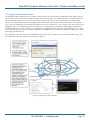
1
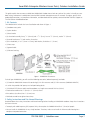
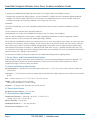
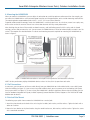
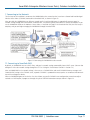
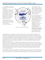
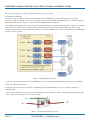
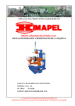
LWN602WA
SmartPath Enterprise Wireless Access Point, Outdoor
Installation Guide
BLACK BOX
®
• High-performance wireless for outdoor environments.
• NEMA 4X rated with an extended temperature range and a waterproof
chassis.
• Can be used outdoors in unprotected locations.
Customer
Support
Information
Order toll-free in the U.S.: Call 877-877-BBOX (outside U.S. call 724-746-5500)
FREE technical support 24 hours a day, 7 days a week: Call 724-746-5500 or fax 724-746-0746
Mailing address: Black Box Corporation, 1000 Park Drive, Lawrence, PA 15055-1018
Web site: www.blackbox.com • E-mail: [email protected]
SmartPath Enterprise Wireless Access Point, Outdoor Installation Guide
Table of Contents
1. Kit Contents............................................................................................................................................................................3
2. Safety Instructions and Site Hazard Warnings.........................................................................................................................3
3. Device, Power, and Environmental Specifications....................................................................................................................4
3.1 Device and Enclosure Specifications...............................................................................................................................4
3.2 Power Specifications.......................................................................................................................................................4
3.3 Environmental Specifications..........................................................................................................................................4
4.
Mounting the LWN602WA.....................................................................................................................................................5
4.1 PoE Connections............................................................................................................................................................5
4.2 Vertical Pole Mount........................................................................................................................................................5
4.3 Horizontal Pole Mount...................................................................................................................................................6
4.4 Flat Surface Mount.........................................................................................................................................................8
5. Attaching External Antennas....................................................................................................................................................9
6. Attaching the Ethernet Cable Waterproof Housing............................................................................................................... 10
7. Connecting to the Network.................................................................................................................................................. 11
7.1 Connecting to SmartPath EMS..................................................................................................................................... 11
7.2 Using the Virtual Access Console................................................................................................................................. 13
8. Deployment and Configuration Tips..................................................................................................................................... 14
9. Ethernet Protector................................................................................................................................................................. 16
10. Troubleshooting................................................................................................................................................................... 17
10.1 Contacting Black Box................................................................................................................................................... 17
10.2Shipping and Packaging............................................................................................................................................... 17
Page 2
724-746-5500 | blackbox.com
SmartPath Enterprise Wireless Access Point, Outdoor Installation Guide
This guide explains how to mount an Black Box LWN602WA Outdoor Access Point to a pole or flat surface in virtually any outdoor setting, and connect it to Black Box SmartPath EMS Network Management over the network. To register, get the latest
product documentation, see compliance information, and download software updates, contact Black Box Technical Support at
724-746-5500 or [email protected].
1. Kit Contents
The LWN602WA kit includes the items listed below and shown in Figure 1.
• (1) outdoor access point
• (1) plane bracket
• (1) base bracket
• (4) sleeve-bolt assembly sleeve, 5⁄8” (16 mm), bolt 1 15⁄16” (5 cm), hex nut 3⁄8” (10 mm), washer 5⁄8” (16 mm)
• (4) round head screws 1⁄4”, lock washer, flat washer
• (4) hex head bolts, 3⁄8”x1⁄2” (10 mm x 13 mm), lock Washer, flat Washer 1⁄2” (13 mm)
• (1) hose strap
• (1) ground cable
• (1) Ethernet housing
Figure 1. LWN602WA kit contents.
To install your LWN602WA, you will need the following accessories (ordered separately) and tools:
• (1) SmartPath LWN602WA Antenna kit containing (2) 2.4-GHz antennas and (2) 5-GHz antennas (LWN600A-WANTK)
• A switch that provides PoE power, or a PoE provisioning device
• (1) shielded CAT5 Ethernet cable rated for outdoor use; length not to exceed 328 feet (100 m)
• Crosshead screwdriver for 1⁄4” (6 mm) x 3⁄8” (10 mm) screws
• Drive sockets (nut drivers) for 3⁄8” (10 mm) nuts
• Flat-blade screwdriver to tighten hose clamp
2. Safety Instructions and Site Hazard Warnings
Read and follow these safety instructions and hazard warnings before installing an LWN602WA outdoors. Keep these instructions
for future reference.
• To comply with radio-frequency (RF) exposure limits, do not place the LWN602WA within 8" (20 cm) of people.
• You can install the LWN602WA in wet, windy locations. Therefore, make sure to install the Ethernet cable housing for a
complete waterproof connection.
724-746-5500 | blackbox.com
Page 3
SmartPath Enterprise Wireless Access Point, Outdoor Installation Guide
• To protect the LWN602WA from lightning, do not place it at the highest point of a building or structure.
• To protect your network from lightning, place a 10-/100-/1000BASE-T shielded CAT6 PoE af compatible lightning protector
(outdoor: AL-CAT6JTW, indoor: HGLN-CAT6JT) inline between the LWN602WA and the rest of the network. Refer to the
installation instructions for the Ethernet protector in the Chapter 9 of this manual.
WARNINGS:
To install the LWN602WA, you must be a qualified installation professional, licensed or certified in accordance with local
regulations.
Use only attachments and accessories specified by Black Box.
During operation, the surfaces of the LWN602WA can become hot. Use caution when handling it.
Make sure that the LWN602WA is connected to a suitably installed ground conductor. Contact the appropriate electrical
inspection authority if you are uncertain that suitable grounding is available.
Do not locate the LWN602WA enclosure near overhead power lines or other electric light or power circuits, or where it can come
into contact with such circuits. During installation, exercise extreme care not to come into contact with these circuits, which can
cause serious injury or death. For proper installation and grounding of the product, refer to national and local electrical codes:
NFPA (National Fire Protection Association) 70, National Electrical Code Article 810 (U.S.); Canadian Electrical Code, Part I, CSA
22.1 and Section 54 (Canada); and if local or national electrical codes are not available, refer to IEC (International Electrotechnical
Commission) 364, Part 1 through 7 (other countries).
Do not connect or disconnect antennas or cables from the LWN602WA during periods of lightning activity.
3. Device, Power, and Environmental Specifications
Understanding the range of specifications for the LWN602WA is necessary for optimal deployment and device operation. The
following specifications describe the hardware components, Power over Ethernet (PoE) electrical requirements, and the
environmental ranges in which the device can operate.
3.1 Device and Enclosure Specifications
Mounting Options — Horizontal or vertical pole mount; pole must be 1" to 3.5" (2.5 cm to 8.9 cm) in diameter, Wall or flat
surface mount
Connectors — (1) RJ-45 Ethernet connector: autosensing 10/100/1000 BASET Mbps; compliant with the IEEE 802.3at standard
for PoE
Size — Without antennas: 3"H x 77⁄8"W x 95⁄8"L (7.6 x 20 x 22.4 cm)
Weight — With antennas: 4.85 lb. (2.199 kg);
With antennas and brackets: 6.05 lb (2.744 kg)
Antennas — (4) N-type female connectors for external antennas
3.2 Power Specifications
PoE Nominal Input Voltage — 48 V, 30 watts
3.3 Environmental Specifications
Temperature Tolerance — Operating: -40 to +131° F (-40 to +55° C);
Storage: -40 to +176° F (-40 to +80° C)
Relative Humidity — Up to 100%
Wind Speed Tolerance — > 165 mph (266 kph)
Environmental Compliance — IP68
Page 4
724-746-5500 | blackbox.com
SmartPath Enterprise Wireless Access Point, Outdoor Installation Guide
4. Mounting the LWN602WA
When you mount the LWN602WA, you can adjust the orientation to vertical for optimum radio transmission. For example, you
can mount the LWN602WA on a non-penetrating roof stand or to a Winegard bracket, often used for mounting satellite dishes.
The mounting bracket accommodates poles with a 1" to 3.5" (2.5 cm to 8.9 cm) diameter.
To provide unobstructed RF coverage, mount the LWN602WA in a relatively open area. At a minimum, mount it on a pole, mast,
of flat surface so that the antennas have at least a three-foot clearance from any nearby obstructions.
After checking that you have all the materials and tools necessary, and familiarizing yourself with the safety and site hazard
warnings, you are ready to mount the unit. You can mount the LWN602WA on a vertical or horizontal pole, or attach it to a flat
surface. These options are described below. The device and mounting accessories required for mounting the LWN602WA are
shown in Figure 2.
Figure 2. LWN602WA mounted on a vertical pole with major devices and accessories called out.
NOTE: For best performance, deploy LWN602WA devices at least 100 feet (30.4 m) apart from each other.
4.1 PoE Connections
In most cases, you can connect an Ethernet cable directly from your LWN602WA to a PoE-enabled switch, or to a PoE injector
inside the building (see Figure 2). If you are not using a PoE-enabled switch, you must connect to an intermediary PoE injector,
then to your switch (see Figure 13). In cases where your LWN602WA is located a significant distance from the building, you can
install an outdoor waterproof PoE injector, available separately (contact Black Box Technical Support at 724-746-5500 or info@
blackbox.com for details).
4.2 Vertical Pole Mount
The following steps explain how to mount the LWN602WA on a vertical pole:
1. Attach the plane bracket to the back of the unit using the hex bolts, lock washers, and flat washers. Tighten the bolts with a
socket or nut driver.
2. Mount the base bracket to the plane bracket using the round-head screws, lock washers, and flat washers. Tighten the screws
with a crosshead screwdriver.
724-746-5500 | blackbox.com
Page 5
SmartPath Enterprise Wireless Access Point, Outdoor Installation Guide
Figure 3. Attaching the base and plane bracket.
3. Thread the open end of the hose strap through the two tabs on the base bracket.
4. Fit the hose strap around the pole and tighten the clamp with a 1/4” (2-cm) slotted screwdriver or a 5/16” (8-mm) drive socket
(or nut) driver.
Figure 4. Install the hose strap.
5. Connect the grounding cable to the grounding lug on the unit, as shown in Figure 10. Connect the other end of the cable to
an appropriate ground.
4.3 Horizontal Pole Mount
The following steps explain how to mount the LWN602WA on a horizontal pole.
1. To mount the LWN602WA on a horizontal pole, first attach the plane bracket to the back of the unit using the four hex-head
bolts with lock washers and flat washers.
2. Mount the base bracket to the plane bracket using the four round-head screws, so that is oriented horizontally. Each screw
should have a lock washer and flat washer.
Page 6
724-746-5500 | blackbox.com
SmartPath Enterprise Wireless Access Point, Outdoor Installation Guide
Figure 5. Attach the plane bracket and the base bracket.
3. Thread the open end of the hose strap through the two tabs on the base bracket.
4. Tighten the hose clamp with a 1/4” (2 cm) slotted screwdriver or a 5/16” (8 mm) drive socket (or nut) driver.
Figure 6. Install the hose strap.
5. Connect the grounding cable to the grounding lug on the unit, as shown in Figure 10. Connect the other end of the cable to
an appropriate ground.
When attaching the LWN602WA to a horizontal pole, such as the arm of a street light, make sure that the face of the device is
perpendicular to the earth for optimal RF coverage.
Figure 7. Line up the unit so it’s perpendicular to the earth when mounted on a horizontal pole.
724-746-5500 | blackbox.com
Page 7
SmartPath Enterprise Wireless Access Point, Outdoor Installation Guide
4.4 Flat Surface Mount
The following steps explain how to mount the LWN602WA on a flat surface. You will need the plane bracket and the four
sleeve-bolt assemblies.
1. Use the plane bracket as a template to mark the location of the mounting holes on the surface.
2. Drill a 5⁄16” (8 mm) hole to a depth of 1.5" (38 mm) into each mark.
3. Remove the nuts and washers and hammer the unthreaded end of a sleeve-bolt assembly into each hole. Make sure the
slotted end of the sleeve goes into the wall. Be sure to leave a minimum of 3/8” (9.5 mm) of the threaded bolt protruding
from the front of the wall.
NOTE: If you are not installing the device on a concrete wall, you can use 2" (5 cm) threaded screws and plastic wall anchors (not
supplied) to mount the device.
Figure 8. Installing the base and plane bracket.
4. Place a lock washer and flat washer on each of the four hex screws and use the screws to attach the plane bracket to the back
of the LWN602WA, as shown in Figure 3.
5. Place the holes in the plane bracket over the mounting bolts and attach the unit using a hex nut, lock washer, and flat washer
on each bolt to tighten the unit to the surface. As you tighten the nuts, the flanges on the back of the bolt sleeve will expand
in the hole, securing the device in place.
Figure 9. Installing the hardware.
Page 8
724-746-5500 | blackbox.com
SmartPath Enterprise Wireless Access Point, Outdoor Installation Guide
6. Connect the grounding cable to the grounding lug on the unit, as shown in Figure 10. Connect the other end of the cable to
an appropriate ground.
Figure 10. Connecting the grounding cable to the grounding lug on the unit.
5. Attaching External Antennas
Once you have grounded your LWN602WA, you are ready to connect the antennas.
NOTE: It is extremely important to properly ground your device to complete your installation.
The omnidirectional antennas are available from Black Box (contact Black Box Technical Support at 724-746-5500 or
[email protected] for details).
These antennas fit the N-type antenna connectors on the top and bottom of the LWN602WA. The two connectors on the bottom of the unit are for the 2.4 GHz antennas, and the two on the top of the unit are for the 5-GHz antennas (device and antennas are labeled).
To connect the antennas, screw them onto the antenna connectors by hand, turning them clockwise until tight.
NOTE: You do not need to use a tool to tighten the antennas or apply self-amalgamating polytetrafluoroethylene (PTFE) tape
around the threads of the connectors to create a waterproof seal.
724-746-5500 | blackbox.com
Page 9
SmartPath Enterprise Wireless Access Point, Outdoor Installation Guide
Figure 11. Attach external antennas.
6. Attaching the Ethernet Cable Waterproof Housing
The following steps explain how to ensure a weatherproof seal for the Ethernet cable using the waterproof housing assembly
shown in Figure 12.
1. Disassemble the waterproof housing. There are three pieces: a threaded nut, a slotted cable grip, and a threaded housing.
2. Slide the threaded nut over the Ethernet cable.
3. Slip the slotted cable grip onto the Ethernet cable in front of the threaded nut.
4. Slide the threaded housing onto the cable and over the cable grip (the grip fits inside the housing).
5. Screw the threaded nut onto the threaded housing.
6. Plug the Ethernet cable into the connector. Screw the assembled housing onto the threaded connector cover.
7. Connect the other end of the Ethernet cable to a PoE-enabled switch, or PoE injector. See Figure 13.
Figure 12. Ethernet housing assembly.
Page 10
724-746-5500 | blackbox.com
SmartPath Enterprise Wireless Access Point, Outdoor Installation Guide
7. Connecting to the Network
The final step to the installation is to connect the LWN602WA to the network so that it can form a Control and Provisioning of
Wireless Access Points (CAPWAP) connection to SmartPath EMS, as shown in Figure 13.
After you cable the LWN602WA to an Ethernet network and it is receiving PoE power, it automatically attempts to get its
network settings through DHCP and contact SmartPath EMS. The process typically takes about five minutes to complete. If you
see the LWN602WA listed on the Monitor > Access Points > SmartPath APs page in the SmartPath EMS GUI, the initial setup is
complete, and you can begin managing the LWN602WA through SmartPath EMS.
Figure 13. Connecting the LWN602WA to the network.
7.1 Connecting to SmartPath EMS
By default, an LWN602WA acts as a DHCP client, and gets its network settings automatically from a DHCP server. (You can also
configure it with static network settings through the CLI. See "Using the Virtual Access Console" in Section 7.2.)
After an LWN602WA has its network settings, it then acts as a CAPWAP client and sends CAPWAP Discovery messages until
SmartPath EMS, acting as the CAPWAP server, responds. CAPWAP is a protocol that access points use to contact and communicate with a management device.
When an LWN602WA goes on-line for the first time without any specific CAPWAP server configuration entered manually or
received as a DHCP option, it progresses through the cycle of CAPWAP connection attempts shown in Figure 14.
724-746-5500 | blackbox.com
Page 11
SmartPath Enterprise Wireless Access Point, Outdoor Installation Guide
(b) If the DNS server cannot
resolve the domain name to an IP
address, the LWN602WA broadcasts CAPWAP Discovery messages on its local subnet. If SmartPath
EMS is on the local network and
responds, they form a secure
CAPWAP connection.
(a) The LWN602WA tries to connect
to SmartPath EMS using the defaultdomain name
“smartpath.<local_domain>”, where
“<local_domain>” is the domain
name that a DHCP server supplied to
the LWN602WA and 12222 is the
UDP port number. If a DNS server has
been configured to resolve that
domain name to an IP address, the
LWN602WA and SmartPath EMS
then form a secure CAPWAP
connection on Port 12222.
If the LWN602WA cannot make a
CAPWAP connection to SmartPath
EMS on Port 12222, it tries to reach it
by using TCP Port 80:
smartpath.<local_domain>:80.
Figure 14. Connecting to SmartPath EMS.
(c) If the first two searches for a
local SmartPath EMS produce
noresults, the LWN602WA tries to
contact SmartPath EMS Online at
redirector.blackbox.com:12222. If
the Black Box redirection server
has a serial number for that
LWN602WA in its ACL, it
responds and they form a secure
CAPWAP connection. If the
LWN602WA cannot make a
CAPWAP connection to
SmartPath EMS Online on UDP
Port 12222, it tries to reach it on
TCP Port 80. If this is unsuccessful,
the LWN602WA returns to the
initial search through a DNS
lookup and repeats the cycle.
If an LWN602WA forms a CAPWAP connection with the redirection server and its serial number or MAC address has been
assigned to a previously created VHM, to a physical SmartPath EMS appliance, or to a SmartPath EMS Virtual Appliance, the
redirection server automatically redirects the CAPWAP connection to that SmartPath EMS instance. The redirection server does
this by sending the LWN602WA the SmartPath EMS domain name or IP address as its new CAPWAP server. If the LWN602WA is
currently using HTTP and it will be redirected to a SmartPath EMS Online VHM, the redirection server also sends it the configuration needed to continue using HTTP. Similarly, if the LWN602WA is accessing the network through an HTTP proxy server, the
redirection server also saves those settings on the LWN602WA so it can reach the SmartPath EMS Online VHM using HTTP
through the HTTP proxy server.
If the redirection server must redirect the LWN602WA to a standalone SmartPath EMS appliance or SmartPath EMS Virtual
Appliance, then you must configure the connection settings on the redirection server that you want it to push to the LWN602WA
to make that connection. The LWN602WA first uses whatever settings are configured on it to reach the redirection server, which
might be on the other side of an HTTP proxy server or firewall that only permits outbound HTTP traffic. Then the redirection
server might supply the LWN602WA with different settings so that the LWN602WA can reach a standalone SmartPath EMS
instance, which might be on the same side of the HTTP proxy server or firewall as the LWN602WA and therefore requires
different connection parameters.
If the LWN602WA serial number or MAC address is in the redirection server but the VHM has not yet been created or the connection settings of the standalone SmartPath EMS have not yet been configured on the redirection server, then the LWN602WA
remains in the redirection server. The SmartPath EMS admin must manually reassign it later to the appropriate SmartPath EMS.
Page 12
724-746-5500 | blackbox.com
SmartPath Enterprise Wireless Access Point, Outdoor Installation Guide
7.2 Using the Virtual Access Console
An LWN602WA connected directly to the network is called a portal. You can also place an LWN602WA within radio range of a
portal so that it forms a wireless link through the portal to the wired network. If the LWN602WA forms a CAPWAP connection
with the Black Box redirection server and its serial number has been entered in an ACL, the redirection server automatically
redirects the CAPWAP connection to the corresponding SmartPath EMS Online VHM (virtual SmartPath EMS). The redirection
server sends the LWN602WA the SmartPath EMS domain name of the IP address as its new CAPWAP server and the name of the
appropriate VHM. If the LWN602WA is currently using HTTP, the redirection server includes the configuration needed for the
LWN602WA to continue using it. Similarly, if the LWN602WA is configured to access the public network through an HTTP proxy
server, the redirection server saves the relevant settings on the LWN602WA so it will continue using the HTTP proxy server when
connecting to SmartPath EMS.
If the redirection server does not have the LWN602WA serial number, the ACL ignores the CAPWAP connection attempts, and
the LWN602WA repeats the connection cycle shown in Figure 15.
Figure 15. Accessing the virtual console.
724-746-5500 | blackbox.com
Page 13
SmartPath Enterprise Wireless Access Point, Outdoor Installation Guide
After logging in to the virtual access console, you can view the status of various functions and make configuration changes. Here
are some commonly used commands.
Use these commands: To do the following:
show interface Check the status of both wired and wireless interfaces.
show interface mgt0 See the network settings (IP address, netmask, default
gateway) and VLAN ID of the mgt0 interface, which is the
management interface of the LWN602WA.
no interface mgt0 dhcp client Disable the DHCP client.
interface mgt0 ip <ip _ addr> <netmask> Set the IP address and netmask of the mgt0 interface.
interface mgt0 native-vlan <id> Set the native (untagged) VLAN that the switch infrastructure in
the surrounding wired and wireless network uses.
show capwap client See CAPWAP client settings and status.
show cluster See the cluster name.
show cluster <string> neighbor Check for any neighboring cluster members.
cluster <string>... Create a cluster and set its parameters.
show ssid See a list of all SSID names.
ssid <string>... Configure an SSID.
interface { wifi0 | wifi1 } ssid <string>
Bind an SSID to a wireless interface in access mode.
save config Save the configuration to Flash.
reboot Reboot the LWN602WA.
Set the following command only when managing LWN602WAs through SmartPath EMS or SmartPath EMS Virtual Appliance.
Do not use this command with SmartPath EMS Online.
capwap client server name <string> Set the IP address or domain name of the CAPWAP server
(SmartPath EMS).
To see a list of commands, and their accompanying CLI Help, type a question mark ( ? ). For example, to see all of the show commands, enter show ?
If you want to find a command that uses a particular character or string of characters, you can do a search using the following
command: show cmds | include <string>, where <string> is the word or string of characters you want to find.
For CLI reference, contact Black Box Technical Support at 724-746-5500 or [email protected].
8. Deployment and Configuration Tips
This section contains tips and suggestions to help you troubleshoot any problems you might experience when you set up your
LWN602WA.
• If the client fails to authenticate to an SSID using a PSK (preshared key), check that the PSK on the client matches that on the
LWN602WA and reset one or both keys if necessary.
• If you manage the LWN602WA through SmartPath EMS Online and it does not show up on the Monitor > Access Points >
SmartPathAPs page, do the following:
- Check if the LWN602WA serial number is listed in the ACL on the Black Box redirection server. Log in to
Smartpath.blackbox.com, and then click Redirector > Monitor > SmartPath AP Access Control List. If the serial number is not
in the ACL, click Enter, type the serial number in the SmartPath AP Serial Number field, and then click “Save.” When done,
reboot the LWN602WA.
Page 14
724-746-5500 | blackbox.com
SmartPath Enterprise Wireless Access Point, Outdoor Installation Guide
- Check connectivity to SmartPath EMS Online:
ping redirector.Black Box.com
capwap ping redirector.Black Box.com
- E nsure that any intervening firewalls allow one of the following sets of services from the LWN602WA to SmartPath EMS
Online:
CAPWAP (UDP 12222), SSH (TCP 22), and HTTPS (TCP 443)
or
HTTP (TCP 80) and HTTPS (TCP 443)
• If a wireless client cannot form an association with an SSID, check that it is within range and is configured to use the same
authentication method as the SSID. For example, if the client is configured to use Open or WEP authentication but the SSID is
set for WPA or WPA2, the client will not be able to associate with the LWN602WA. To see the security settings for an SSID, click
Configuration > SSIDs > ssid_name > Advanced Access Security Settings, and look at the SSID access security type, the key
management method, and the encryption method.
• If the client associates and authenticates itself, but the LWN602WA cannot forward traffic, check that the LWN602WA is
assigning the correct user profile, and if so, that it is also assigning the correct VLAN. To see the user profile and VLAN that an
LWN602WA assigns to a client, log in to SmartPath EMS, click Monitor > Clients > Active Clients > client_mac_address. Check
the user profile attribute and VLAN. If they are correct, then check that the client has received its network settings through
DHCP. To check connectivity to a DHCP server, click Tools > VLAN Probe, choose the LWN602WA with which the client is
associated from the SmartPath AP drop-down list, and enter IDs for the VLAN range that you want to check. Click Start to send
a DHCP DISCOVER message, and see if it elicits a response. Also check that the VLAN configuration for the port on the
connecting switch is correct.
To remove all settings and return the configuration to its factory default settings, enter the reset config command or use a pin to
724-746-5500 | blackbox.com
Page 15
SmartPath Enterprise Wireless Access Point, Outdoor Installation Guide
press the Reset button on the chassis and hold it down for at least 10 seconds.
9. Ethernet Protector
In most cases, you can connect an Ethernet cable directly from the LWN602WA to a PoE-enabled switch or PoE injector
(LPS001A-J) inside the building. In some cases, you might need to install an outdoor waterproof PoE injector, available separately
(contact Black Box Technical Support at 724-746-5500 or [email protected] for details).
The LWN602WA and outdoor PoE injectors have built-in surge protection to guard against lightning strikes. However, the network
where the Ethernet cable enters the building requires protection as well. To prevent the indoor network from power surges
caused by lightning, place an Ethernet protector (indoosr: AL-CAT6JTW; outdoors: HGLN-CAT6JT) inline between the LWN602WA
and the rest of the network.
Figure 16. Adding lightning arrestors.
1. Attach the Ethernet protection device to the building at the entry point of the shielded Ethernet cable from the LWN602WA.
2. Make the following connections:
• Ground the device by running a wire from the grounding stud to a grounded object, such as a water pipe, gas pipe, or
grounding rod.
• Connect the shielded Ethernet cable from the LWN602WA to the port labeled "Line Side," and connect another Ethernet cable
from the port labeled "Equipment Side" to the network.
Figure 17. Connecting the PoE injector inline.
Page 16
724-746-5500 | blackbox.com
SmartPath Enterprise Wireless Access Point, Outdoor Installation Guide
Ethernet Protector Specifications
• 10/100/1000BASE-T Ethernet
• GR-1089 Intra-Building rated
10. Troubleshooting
10.1 Contacting Technical Support
If you determine that your LWN602WA is malfunctioning, do not attempt to alter or repair the unit. It contains no
user-serviceable parts. Contact Black Box Technical Support at 724-746-5500 or [email protected].
Before you do, make a record of the history of the problem. We will be able to provide more efficient and accurate assistance if
you have a complete description, including:
• the nature and duration of the problem.
• when the problem occurs.
• the components involved in the problem.
• any particular application that, when used, appears to create the problem or make it worse.
10.2 Shipping and Packaging
If you need to transport or ship your LWN602WA:
• Package it carefully. We recommend that you use the original container.
• If you are returning the unit, make sure you include everything you received with it. Before you ship for return or repair, contact
Black Box to get a Return Authorization (RA) number.
724-746-5500 | blackbox.com
Page 17
NOTES
Page 18
724-746-5500 | blackbox.com
NOTES
724-746-5500 | blackbox.com
Page 19
Black Box Tech Support: FREE! Live. 24/7.
Tech support the
way it should be.
Great tech support is just 30 seconds away at 724-746-5500 or blackbox.com.
About Black Box
Black Box provides an extensive range of networking and infrastructure products. You’ll find everything from cabinets and racks
and power and surge protection products to media converters and Ethernet switches all supported by free, live 24/7 Tech Support
available in 30 seconds or less.
© Copyright 2012. Black Box Corporation. All rights reserved. Black Box® and the Double Diamond logo are registered trademarks, and SmartPath is a
trademark, of BB Technologies, Inc. Any third-party trademarks appearing in this white paper are acknowledged to be the property of their respective owners.
LWN602WA Installation Guide, version 1
724-746-5500 | blackbox.com