1
User’s Manual
SRP-500
Inkjet Printer
Rev. 1.06
http://www.bixolon.com
SRP-500
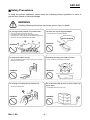
■ Safety Precautions
In using the present appliance, please keep the following safety regulations in order to
prevent any hazard or material damage.
WARNING
Violating following instructions can cause serious injury or death.
Do not plug several products in one multi-outlet.
•
•
•
•
You must use only the supplied adapter.
This can provoke over-heating and a fire.
If the plug is wet or dirty, dry or wipe it before usage.
If the plug does not fit perfectly with the outlet, do not plug in.
Be sure to use only standardized multi-outlets.
• It is dangerous to use other adapters.
ONLY SUPPLIED ADAPTER
PROHIBITED
PROHIBITED
Do not pull the cable to unplug.
Keep the plastic bag out of children’s reach.
• This can damage the cable, which is the origin of a fire or a
breakdown of the printer.
• If not, a child may put the bag on his head.
PROHIBITED
PROHIBITED
Do not plug in or unplug with your hands wet.
Do not bend the cable by force or leave it under any
heavy object.
• You can be electrocuted.
PROHIBITED
Rev. 1.06
• A damaged cable can cause a fire.
PROHIBITED
-2-
SRP-500
CAUTION
Violating following instructions can cause slight wound or damage the appliance.
If you observe a strange smoke, odor or noise from
the printer, unplug it before taking following
measures.
Keep the desiccant out of children’s reach.
• If not, they may eat it.
• Switch off the printer and unplug the set from the mains.
• After the disappearance of the smoke, call your dealer to
repair it.
TO UNPLUG
PROHIBITED
PRINTER
Install the printer on the stable surface.
• If the printer falls down, it can be broken and you can hurt
yourself.
Use only approved accessories and do not try to
disassemble, repair or remodel it for yourself.
• Call your dealer when you need these services.
• Do not touch the blade of auto cutter.
PRINTER
DISASSEMBLING
PROHIBITED
PROHIBITED
PRINTER
Do not let water or other foreign objects in the
printer.
Do not use the printer when it is out of order. This
can cause a fire or an electrocution.
• If this happened, switch off and unplug the printer before
calling your dealer.
• Switch off and unplug the printer before calling your dealer.
PROHIBITED
TO UNPLUG
PRINTER
PRINTER
DEALER
Rev. 1.06
-3-
SRP-500
All rights reserved. No part of this publication may reproduced, stored in a retrieval, or
transmitted in any form or by any means, electronic, mechanical, photocopying, recording,
or otherwise, without the prior written permission of BIXOLON.
No patent liability is assumed with respect to the use of the information contained herein.
While every precaution has been taken in the preparation of this book, BIXOLON assumed
no responsibility for errors or omissions. Neither is any liability assumed for damages
resulting from the use of the information contained herein.
Neither BIXOLON nor its affiliates shall be liable to the purchaser of this product or third
parties for damages, losses, costs, or expenses incurred by purchaser or third parties as a
result of : accident, misuse, or abuse of this product or unauthorized modifications, repairs,
or alterations to this product, or (excluding the U.S) failure to strictly comply with
BIXOLON’ s operating and maintenance instructions.
BIXOLON shall not be liable against any damages or problems arising from the use of any
options or ant consumable products other than those designated as Original BIXOLON
products.
■ Notice
We at BIXOLON maintain ongoing efforts to enhance and upgrade the functions and
quality of all our products. In following, product specifications and/or user manual content
may be changed without prior notice.
Rev. 1.06
-4-
SRP-500
■ EMC and Safety standards Applied
Product Name : SRP-500
The following standards are applied only to the printers that are so labeled.
Europe :
CE marking, TUV/GS : EN60950 ; 1999
North America :
EMI : FCC Class A
Safety standards :
UL / C-UL : UL60950-3rd.
National : CB-scheme :
IEC 60950 ; 1999
■ Warning
The connection of a non-shielded printer interface cable to this printer will invalidate the
EMC standards of this device.
You are cautioned that changes or modifications not expressly approved by the party
responsible for compliance could void your authority to operate the equipment.
■ CE Marking
The printer conforms to the following Directive and Norms
Directive 89/336/EEC
EN 55022 Class A :1998
EN 55024 : 1998
(EN 61000-4-2 : 1995+A1 : 1998)
(EN 61000-4-3 : 1996)
(EN 61000-4-4 : 1995)
(EN 61000-4-5 : 1995)
(EN 61000-4-6 : 1996)
(EN 61000-4-11 : 1994)
EN 61000-3-2 : 1995+A1 : 1998+A2 : 1998)
EN 61000-3-3 : 1995
Directive 73/23/EEC
Safety : EN 60950 ; 1999
■ Waste Electrical and Electric Equipment (WEEE)
This marking shown on the product or its literature, indicates that is should not
be disposed with other household wastes at the end of its working life, To
prevent possible harm to the environment or human health from uncontrolled
waste disposal, please separate this from other types of wastes and recycle it
responsibly to promote the sustainable reuse of material resources. Household
users should contact either the retailer where they purchased this product, or their local
government office, for details of where and how they can take this item for environmentally
safe recycling. Business users should contact their supplier and check the terms and
conditions of the purchase contract. This product should not be mixed with other
commercial wastes for disposal.
■ Label Material
* Control Label: PC
* Other Labels: PET
Rev. 1.06
-5-
SRP-500
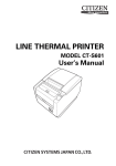
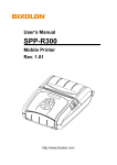
■ Introduction
* Front view
* Rear view
Rev. 1.06
-6-
SRP-500
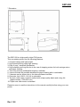
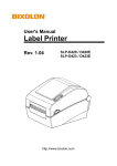
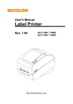
* Dimension
226
172
152
The SRP-500 is a high-quality inkjet POS printer.
This one-station printer has the following features.
1. Compact design and light-weight.
2. High-speed printing using logic-seeking.
3. Easy to use : clamshell mechanism.
4. High reliability and long life due to the use of stepping motors for both carriage return
and paper feeding.
5. Two color printing (red/black/blue/green) available.
6. Various formats are possible because the paper feeding pitch is selectable.
7. 2 drawers can be driven due to the internal drawer interface.
8. Character font (12X12, 12X14) is selectable.
9. The auto cutter uses a circular method with a high-quality blade and a long life.
(Approximately 1,000,000 cuts)
10. Paper near end sensor is standard.
Please be sure to read the instructions in this manual carefully before using your new
printer
Rev. 1.06
-7-
SRP-500
■ Table of Contents
1. Setting Up the Printer ................................................................................................... 9
1-1 Unpacking.................................................................................................................. 9
1-2 Choosing a place for the printer............................................................................... 10
1-3 Using the control panel ............................................................................................ 11
2. Connecting the cables................................................................................................ 12
2-1 Connect the AC adapter according to the following procedure................................ 12
2-2 Connecting the interface cable ................................................................................ 13
3. Setting the Dip Switches ............................................................................................ 14
3-1 Serial Interface (RS232C)........................................................................................ 15
3-2 Parallel / USB Interface (Parallel-IEEE1284)........................................................... 16
4. Setting the memory switches .................................................................................... 17
4-1 Setting methods....................................................................................................... 17
4-2 Memory switch description ...................................................................................... 17
4-3 Star emulation ......................................................................................................... 18
5. Installing new Ink cartridge(s) ................................................................................... 21
6. Installing or replacing paper roll ............................................................................... 23
7. Self Test....................................................................................................................... 25
8. Hexadecimal Dumping ............................................................................................... 26
9. Specification ............................................................................................................... 27
10. Appendix - Troubleshooting .................................................................................... 28
10-1 The printer does not start printing .......................................................................... 28
10-2 The printer stops printing ....................................................................................... 28
10-3 You want to check the operation of the printer by itself ......................................... 29
10-4 Printing is poor....................................................................................................... 29
Rev. 1.06
-8-
SRP-500
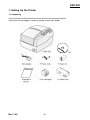
1. Setting Up the Printer
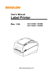
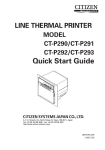
1-1 Unpacking
Your printer box should include the items shown in the illustration below.
If any items are damaged or missing, please contact your dealer.
CD
Rev. 1.06
-9-
SRP-500
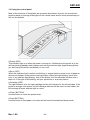
1-2 Choosing a place for the printer
1-2-1 Avoid locations that are subject to direct sunlight or excessive heat.
1-2-2 Avoid using or storing the printer in a place subject to excessive temperature or
moisture.
1-2-3 Do not use or store the printer in a dirty location.
1-2-4 When setting up the printer, choose a stable, horizontal location.
1-2-5 Intense vibration or shock may damage the printer.
1-2-6 Ensure the printer has enough space to be used easily.
Rev. 1.06
- 10 -
SRP-500
1-3 Using the control panel
Most of the functions of this printer are governed by software, but you can monitor the
printer’s status by looking at the lights on the control panel and for some procedures you
will use the buttons.
● Power (LED)
This indicator light is on when the power is turned on. It blinks when the printer is in the
self test printing standby state. Always wait until this indicator light stops blinking before
you start using the printer and before you turn it off.
● Error (LED)
When this indicator light is on(but not blinking), it means that the printer is out of paper or
almost out of paper or the printer covers are open. When this light blinking, there is an
error. If you see this light blinking, turn off the printer for a few seconds and then turn it
black on. If the light is still blinking, call your supervisor or a service person.
● Cartridge (LED)
The right indicator is for the right cartridge and the left indicator for the left cartridge. If the
printer is a single color printer, the left cartridge indicator will be used. In most cases, the
left cartridge is black, and the right is a color.
● Clean (BUTTON)
Use this button to clean the printer head.
● Feed (BUTTON)
Use this button to feed paper or to start self test and for hexadecimal dump mode.
Rev. 1.06
- 11 -
SRP-500
2. Connecting the cables
※ CAUTION
Before connecting the printer to the power supply, make sure that the voltage and power
specifications match the printer's requirements. Using an incorrect power supply can
cause serious damage to the printer.
2-1 Connect the AC adapter according to the following procedure
2-1-1 Make sure the printer is turned off.
2-1-2 Plug the AC adapter cable into the printer's power connector.
2-1-3 Plug the power cord into the outlet, and turn on the power.
Rev. 1.06
- 12 -
SRP-500
2-2 Connecting the interface cable
Connect the printer to the host ECR (host computer) though an interface cable matching
the specification of the printer and the host ECR (host computer).
Be sure to use a drawer that matches the printer's specification.
Depending on the interface your system uses, either connect the serial, parallel or USB
communication cable to the appropriate connector on the back of the printer. Cables are
provided by your dealer or system installer.
Connect the interface cable according to the following procedure.
2-2-1 Turn off printer and the ECR (host computer) host.
2-2-2 Plug the interface cable into the interface connector on the printer then fasten the
screw on both sides of the connector.
2-2-3 Plug the drawer kick-out cable into the drawer kick-out connector on the printer.
(When removing the drawer kick-out cable, press on the connector's clip while pulling
out.)
Rev. 1.06
- 13 -
SRP-500
3. Setting the Dip Switches
Although the factory settings are best for almost all users, if you have special requirements,
you can change the DIP switch. If you need to change settings, follow the steps below to
make your changes.
- Make sure the printer is turned off.
- Remove the screw from the DIP switch cover. Then take off the DIP switch cover,
which is shown in the illustration below.
- Set the switches using a pointed tool, such as tweezers or a small screwdriver.
- Replace the DIP switch cover. Then secure it with the screw.
- The new settings take effect when you turn on the printer.
※ NOTE
Turn off the printer before removing the DIP switch cover to prevent an electric short,
which can damage the printer.
Rev. 1.06
- 14 -
SRP-500
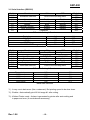
3-1 Serial Interface (RS232C)
Switch
1-1
1-2
1-3
1-4
1-5
1-6
1-7
1-8
Function
ON
Emulation Selection
OFF
Default
OFF
OFF
ON
OFF
OFF
OFF
ON
OFF
Refer to the following table
Auto cutter
Cartridge
Density*1)
Special Function *2)
Near end sensor
Enable
Disable
one cartridge
two cartridges
Bold
Normal
Enable
Disable
Enable
Disable
Undefined
DIP switch Setting 1 Function
Emulation
BXL/POS
STAR
CITIZEN
BXL/POS-KP *3)
1-1
OFF
OFF
ON
ON
1-2
OFF
ON
OFF
ON
Emulation Selection
Switch
2-1
2-2
2-3
2-4
2-5
2-6
2-7
2-8
Function
Data receive error
Hand Shaking
Word length
Parity check
Parity selection
Baud rate selection
ON
Print “?”
Reserved
DTR/DSR
7bit
Enable
EVEN
OFF
Ignore
Default
OFF
OFF
OFF
OFF
OFF
OFF
OFF
OFF
XON/XOFF
8bit
Disable
ODD
Refer to the following table
DIP switch Setting 2 Function
Transmission
2400 baud
4800 baud
9600 baud
19200 baud
2-7
ON
OFF
OFF
ON
Baud Rate selection
2-8
ON
ON
OFF
OFF
*1) : It may use in dark area. (like a restaurant). But printing speed to be slow down.
*2) : Enable = Automatically print NV bit image #1 after cutting.
*3) : Kitchen Printer mode : A alarm is generated by printer after auto-cutting and
in paper-end error. (It needs buzzer accessory)
Rev. 1.06
- 15 -
SRP-500
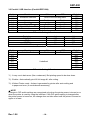
3-2 Parallel / USB Interface (Parallel-IEEE1284)
Switch
1-1
1-2
1-3
1-4
1-5
1-6
1-7
1-8
Function
ON
Emulation Selection
OFF
Default
OFF
OFF
ON
OFF
OFF
OFF
ON
OFF
Refer to the following table
Auto cutter
Cartridge
Density*1)
Special Function *2)
Near end sensor
Enable
Disable
one cartridge
two cartridges
Bold
Normal
Enable
Disable
Enable
Disable
Undefined
DIP switch Setting 1 Function
Emulation
BXL/POS
STAR
CITIZEN
BXL/POS-KP *3)
1-1
OFF
OFF
ON
ON
1-2
OFF
ON
OFF
ON
Emulation Selection
Switch
2-1
2-2
2-3
2-4
2-5
2-6
2-7
2-8
Function
Auto Line Feed
ON
Enable
OFF
Disable
Undefined
Default
OFF
OFF
OFF
OFF
OFF
OFF
OFF
OFF
DIP switch Setting 2 Function
*1) : It may use in dark area. (like a restaurant). But printing speed to be slow down.
*2) : Enable = Automatically print NV bit image #1 after cutting.
*3) : Kitchen Printer mode : A alarm is generated by printer after auto-cutting and
in paper-end error. (It needs buzzer accessory)
※ NOTE
Changes in DIP switch settings are recognized only when the printer power is turned on or
when the printer is reset by using the interface. If the DIP switch setting is changed after
the printer power is turned on, the change does not take effect until the printer is turned on
again or is reset.
Rev. 1.06
- 16 -
SRP-500
4. Setting the memory switches
4-1 Setting methods
1) Memory switch setting utility (Please check out our bundle CD)
2) Control from emulation command (refer to command manual)
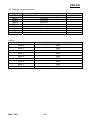
4-2 Memory switch description
SW no.
MSW1
MSW2
MSW3
MSW4
MSW5
MSW6
MSW7
MSW8
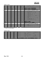
MSW1 details
1-5
1-4
0
0
0
0
0
0
0
0
0
0
0
1
0
1
0
1
0
1
0
1
0
1
0
1
0
1
0
1
0
1
0
1
0
1
1
0
1
0
1
0
Description
Selection for the default code page
Reserved
Reserved
Reserved
Reserved
Reserved
Reserved
Reserved
1-3
0
0
0
0
0
0
0
0
0
0
0
0
1
1
1
1
1
0
0
0
1-2
0
0
0
1
1
0
0
0
0
1
1
1
0
0
0
1
1
0
0
1
1-1
0
1
1
0
0
0
0
1
1
0
1
1
0
1
1
0
1
1
1
1
1-0
0
0
1
0
1
0
1
0
1
1
0
1
0
0
1
1
1
0
1
0
*1) Only Font B available
Rev. 1.06
- 17 -
remark
Character Table
Page 0 (PC437 : U.S.A)
Page 2 (PC850 : Multilingual)
Page 3 (PC860 : Portuguese)
Page 4 (PC863 : Canadian-French)
Page 5 (PC865 : Nordic)
Page 16 (WPC1252 : Latin I)
Page 17 (PC866 : Cyrillic #2)
Page 18 (PC852 : Latin II)
Page 19 (PC858 : Euro)
Page 21 (PC862 : Hebrew DOS code)
Page 22 (PC864 : Arabic)
Page 23 (Thai character code 42)
Page 24 (WPC1253 : Greek)
Page 26 (WPC1257 : Baltic)
Page 27 (Farsi) *1)
Page 29 (PC737 : Greek)
Page 31 (Thai character code 14)
Page 34 (Thai character code 11)
Page 35 (Thai character code 18)
Page 38 (PC928 : Greek)
SRP-500
4-3 Star emulation
4-3-1 Setting methods
1) Memory switch setting utility (Please check out our bundle CD)
2) Control from emulation command (refer to command manual)
Memory Switches are from MSW 0 to MSW 8. They are stored in non-volatile memory
(flash memory). To change the settings, send the following commands from the host.
[Name]
[Code]
Set Memory Switch
ASCII
ESC
GS
#
m {n1 n2 n3 0n4}0 ... {n1 n2 n3 n4}8 LF NUL
Hexadecimal
1B
1D
23
m {n1 n2 n3 0n4}0 ... {n1 n2 n3 n4}8 0A 00
Decimal
27
29
35
m {n1 n2 n3 0n4}0 ... {n1 n2 n3 n4}8 10 0
[Defined Region] m = "W", "T", ",", "+", "-", "@"
"0" ≤ n1,n2,n3,n4 ≤ "9",
"A" ≤ n1,n2,n3,n4 ≤ "F"
[Function]
Sends command to write after defining Memory Switch using the definition command
specified by the following classes to set the Memory Switch. The printer is automatically
reset after writing the setting defined by that command to the non-volatile memory.
Do not turn off the power to the printer while sending commands to the non volatile
memory. Doing so will destroy the Memory Switch setting. It is also possible for all Memory
Switch settings to become offset to their initial, default settings.
Consider the life of the non-volatile memory and avoid over-use of this command.
Function
Data Definition (Data Specification)
Data definition (set specified bit)
Data definition (clear specified bit)
Data Definition (clear all data)
Definition data write and reset
Definition data write and reset and test print
Class
Definition
Definition
Definition
Definition
Write
Write
m
","
"+"
"-"
"@"
"W"
"T"
{n1 n2 n3 0n4}0 ... {n1 n2 n3 n4}8
{n1 n2 n3 0n4}0 ... {n1 n2 n3 n4}8
{n1 n2 n3 0n4}0 ... {n1 n2 n3 n4}8
{n1 n2 n3 0n4}0 ... {n1 n2 n3 n4}8
Fixed at "0000"
Fixed at "0000"
Fixed at "0000"
(Ex) Memory Switch 1-8 = 0; Memory Switch 2-7 = 1: Memory Switch 2-A =1 for a test print:
PRINT #1, CHR$(&H1B);CHR$(&H1D);CHR$(&H23);CHR$(&H2D); ' <ESC><GS> # PRINT #1, CHR$(&H30);CHR$(&H30);CHR$(&H30);CHR$(&H30); ' 0000
PRINT #1, CHR$(&H30);CHR$(&H31);CHR$(&H30);CHR$(&H30); ' 0100
PRINT #1, CHR$(&H30);CHR$(&H30);CHR$(&H30);CHR$(&H30); ' 0000
PRINT #1, CHR$(&H30);CHR$(&H30);CHR$(&H30);CHR$(&H30); ' 0000
PRINT #1, CHR$(&H30);CHR$(&H30);CHR$(&H30);CHR$(&H30); ' 0000
PRINT #1, CHR$(&H30);CHR$(&H30);CHR$(&H30);CHR$(&H30); ' 0000
PRINT #1, CHR$(&H30);CHR$(&H30);CHR$(&H30);CHR$(&H30); ' 0000
PRINT #1, CHR$(&H30);CHR$(&H30);CHR$(&H30);CHR$(&H30); ' 0000
PRINT #1, CHR$(&H30);CHR$(&H30);CHR$(&H30);CHR$(&H30);CHR$(&H0A);CHR$(0); ' 0000 <LF><NUL>
PRINT #1, CHR$(&H1B);CHR$(&H1D);CHR$(&H23);CHR$(&H2B); ' <ESC><GS> # +
PRINT #1, CHR$(&H30);CHR$(&H30);CHR$(&H30);CHR$(&H30); ' 0000
PRINT #1, CHR$(&H30);CHR$(&H30);CHR$(&H30);CHR$(&H30); ' 0000
PRINT #1, CHR$(&H30);CHR$(&H34);CHR$(&H38);CHR$(&H30); ' 0480
PRINT #1, CHR$(&H30);CHR$(&H30);CHR$(&H30);CHR$(&H30); ' 0000
PRINT #1, CHR$(&H30);CHR$(&H30);CHR$(&H30);CHR$(&H30); ' 0000
PRINT #1, CHR$(&H30);CHR$(&H30);CHR$(&H30);CHR$(&H30); ' 0000
PRINT #1, CHR$(&H30);CHR$(&H30);CHR$(&H30);CHR$(&H30); ' 0000
PRINT #1, CHR$(&H30);CHR$(&H30);CHR$(&H30);CHR$(&H30); ' 0000
PRINT #1, CHR$(&H30);CHR$(&H30);CHR$(&H30);CHR$(&H30); CHR$(&H0A);CHR$(0); ' 0000<LF><NUL>
PRINT #1, CHR$(&H1B);CHR$(&H1D);CHR$(&H23);CHR$(&H54); ' <ESC><GS> # T
PRINT #1, CHR$(&H30);CHR$(&H30);CHR$(&H30);CHR$(&H30);CHR$(&H0A);CHR$(&H0); ' 0000 <LF><NUL>
Rev. 1.06
- 18 -
SRP-500
4-3-2 Memory switch description
SW no.
MSW0
MSW1
MSW2
MSW3
MSW4
MSW5
MSW6
MSW7
MSW8
Description
Selection for the default code page
Reserved
Reserved
Reserved
Selection for Carriage return
Reserved
Reserved
Reserved
Reserved
Default
Rev. 1.06
SW no.
Factory Setting (n1 n2 n3 n4)
MSW 0
“0000”
MSW 1
“0000”
MSW 2
“0000”
MSW 3
“0000”
MSW 4
“0000”
MSW 5
“0000”
MSW 6
“0000”
MSW 7
“0000”
MSW 8
“0000”
- 19 -
remark
SRP-500
MSW1 details
1-5
1-4
0
0
0
0
0
0
0
0
0
0
0
1
0
1
0
1
0
1
0
1
0
1
0
1
0
1
0
1
0
1
0
1
0
1
1
0
1
0
1
0
1-3
0
0
0
0
0
0
0
0
0
0
0
0
1
1
1
1
1
0
0
0
1-2
0
0
0
1
1
0
0
0
0
1
1
1
0
0
0
1
1
0
0
1
1-1
0
1
1
0
0
0
0
1
1
0
1
1
0
1
1
0
1
1
1
1
1-0
0
0
1
0
1
0
1
0
1
1
0
1
0
0
1
1
1
0
1
0
Character Table
Page 0 (PC437 : U.S.A)
Page 2 (PC850 : Multilingual)
Page 3 (PC860 : Portuguese)
Page 4 (PC863 : Canadian-French)
Page 5 (PC865 : Nordic)
Page 16 (WPC1252 : Latin I)
Page 17 (PC866 : Cyrillic #2)
Page 18 (PC852 : Latin II)
Page 19 (PC858 : Euro)
Page 21 (PC862 : Hebrew DOS code)
Page 22 (PC864 : Arabic)
Page 23 (Thai character code 42)
Page 24 (WPC1253 : Greek)
Page 26 (WPC1257 : Baltic)
Page 27 (Farsi) *1)
Page 29 (PC737 : Greek)
Page 31 (Thai character code 14)
Page 34 (Thai character code 11)
Page 35 (Thai character code 18)
Page 38 (PC928 : Greek)
*1) Only Font B available.
MSW4 details
4-3
4-2
0
0
0
0
0
0
0
0
0
1
0
1
Rev. 1.06
4-1
0
0
1
1
0
0
4-0
0
1
0
1
0
1
Function
<CR>Command : Ignore, <LF>Command : CR+LF
<CR>Command : CR, <LF>Command : LF
<CR>Command : CR+LF, <LF>Command : Ignore
<CR>Command : CR+LF, <LF>Command : LF
<CR>Command : CR, <LF>Command : CR+LF
<CR>Command : CR+LF, <LF>Command : CR+LF
- 20 -
SRP-500
5. Installing new Ink cartridge(s)
5-1 Remove new ink cartridge from sealed pouch.
(Hold cartridge by round plastic tab to avoid
contamination)
5-2 Remove Mylar from face of new cartridge.
※ CAUTION
Do not touch ink cartridge's metallic connector
surface with your fingers. Doing so will
contaminate the connector and produce bad print
quality.
5-3 Turn the printer on and open the front
cover of printer.
※ NOTE
If you take out ink cartridge while you do
intend to replace it, turn on the printer first.
Otherwise the count of ink drop isn’t reset
5-4 Pull down cartridge holder.
Rev. 1.06
- 21 -
SRP-500
5-5 Take out old ink cartridge(s). Place new
cartridge(s) into carriage. Hold plastic
tab to ensure clean installation. Black
cartridge goes into the left carriage. The
color cartridge goes into right carriage.
(tab faces front of printer.)
5-6 Close cartridge holder.
5-7 Close front cover of printer.
Rev. 1.06
- 22 -
SRP-500
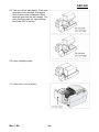
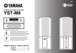
6. Installing or replacing paper roll
※ CAUTION
Notice the caution label and do not touch the auto cutter blade when you open rear cover.
6-1 To prevent data loss, make sure that the printer is not receiving data.
6-2 Open the rear cover by pressing the open button and push the arrow mark back.
Rev. 1.06
- 23 -
SRP-500
6-3 Remove the used paper roll core if
there is one.
6-4 Insert the paper roll as shown.
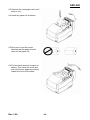
6-5 Be sure to note the correct
direction that the paper should
come off the paper roll.
6-6 Pull out small amount of paper as
shown. Then close the cover and
tear off the extra paper by pulling it
toward the front of the printer.
Rev. 1.06
- 24 -
SRP-500
7. Self Test
The self test lets you know if your printer is operating properly.
It checks the control circuits, printer mechanisms, print quality, ROM version, and DIP
switch settings.
The test is independent of any other equipment or software, so it is a good idea to run it
when you first set up the printer or if you have any trouble. If the self test works correctly,
the problem is in the other equipment or the software, not the printer.
7-1 Make sure the printer is turned off and the printer cover is closed properly.
7-2 While holding down the Feed button, turn on the printer and continue to hold until the
paper begins to feed. The self test prints the printer settings and cuts the paper and
pauses. (The power light blinks.).
7-3 Press the Feed button to continue printing the rolling ASCII pattern. Repeat for the
nozzle pattern, NV bit image(s).
7-4 The self test mode terminates after printing NV bit image(s) automatically.
Rev. 1.06
- 25 -
SRP-500
8. Hexadecimal Dumping
This feature allows experienced users to see exactly what data is coming to the printer.
This can be useful in finding software problems. When you turn on the hexadecimal dump
function, the printer prints all commands and other data in hexadecimal format along with a
guide section to help you find specific commands.
To use the hexadecimal dump feature, follow these steps:
8-1 After you make sure that the printer is off, open the front cover of the printer.
8-2 Hold down the Feed button while you turn on the printer.
8-3 Close the front cover.
8-4 Run any software program that sends data to the printer. The printer prints
"Hexadecimal Dump" and then all the codes it receives in a two-column format. The
first column contains the hexadecimal codes and the second column gives the ASCII
characters that correspond to the codes.
- A period(.) is printed for each code that has no ASCII equivalent
8-5 When the printing finishes, turn off the printer.
Rev. 1.06
- 26 -
SRP-500
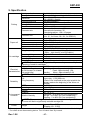
9. Specification
Printing method
Printing direction
Serial ink jet matrix method
Bidirectional(logic seeking) with friction feed
104 x 96(dpi): Text
Resolution
208 x 96(dpi): Graphic
Characters per line
Max 42(characters)
Printing speed
6.5 LPS (Lines Per Second) at 40 columns
Printing
Printing Width
61.5mm
Line Interval
4.233mm (1/6”)
Alphanumeric characters: 95
Character sets
International characters: 32
Extended graphics : 128 x 12 pages
14 x 12 / 12 x 12
Character font
(24 x 12 ; for Korea, 20 x 24 ; for GB2312)
Normal paper
Type
Width : 76 ± 0.5(mm)
Size
0.06 to 0.085(mm)
Paper roll
Thickness
Maximum outside diameter ø 83mm
Paper core inside diameter ø 10 to 12.5(mm)
Model
RIC-500B,R (HP 6602a,r)
Firing frequency
3.0KHz – low density printing(Text)
1.5KHz – high density printing(Graphic)
19.9 ± 0.5V
Operating Voltage
60 Ω
Ink cartridge Resistance
0~45 °C
Operating Temperature
Date of expiration
2 years after production (at normal temperature)
※ NOTE : Follow the laws or regulations of your country or community for
disposing of used ink cartridges.
24VDC
Supply voltage
Operating Mean : Approximately 0.5A
Current consumption
Electrical
Peak : Approximately 1.5A
(at 24V,except for drawer
characteristics
Standby
Mean : Approximately 0.3A
kick-out driving)
※ NOTE : Maximum 1A for drawer kick-out driving.
Mechanism : 18,000,000 lines
Life
Auto cutter : 1,500,000 cuts
(End of Life is defined as the point at which the
Firing frequency
Reliability
printer reaches the beginning of the Wear out
Period.)
MTBF
30,000 hours
0 ° to 45 °C
Operating
-20 ° to 60 °C
Storage
-40 ° to 70 °C
Shipping
Environmental
Operating : 10 to 80% RH (non-condensing)
condition
Storage : 10 to 90% RH (non-condensing)
Relative Humidity
Shipping : 5 to 90% RH (non-condensing)
※ NOTE : Exposure to high or low temperatures for periods of greater than
48 hours will lead to significantly reduced cartridge life.
Approx. Wt : 2.7Kg
Printer
Weight
Shipping. Wt : 3.5Kg
* This equipment is indooruse and all the communication hiring are limited to inside of the building.
* The switch is the disconnecting device. Turn off switch from any hazard.
Rev. 1.06
- 27 -
SRP-500
10. Appendix - Troubleshooting
This chapter gives solutions to some printer problems you may have.
10-1 The printer does not start printing
10-1-1 Are any of the control panel lights on?
If no control panel lights are on, check the following:
- Make sure that the printer is turned on.
- Make sure that the power supply cable is correctly plugged into the printer and
to the power outlet.
10-1-2 If any of the lights are on, please check the following:
- If the Power light is blinking, the printer is not yet ready. Wait until the light quits
blinking and the printer is ready to use.
- If the Error light is on (but not blinking), the printer is off line. Check to see that the
covers are closed and check the paper state. See Chapter 6 for instructions on
installing or replacing the paper roll.
- If the Error light is blinking, there is an error. In this case, turn off the printer for a
few seconds and then turn it back on. If the light is still blinking, call your
supervisor or service person.
- If the Cartridge lights (LH/RH) is on, check the cartridges in the printer. See
chapter 5 for instruction on installing new ink cartridges.
10-2 The printer stops printing
- If the Error light is on (but not blinking), the printer is off line. Check to see that the covers
are closed and check the paper state. See Chapter 6 for instructions on installing or
replacing the paper roll.
- If the Error light is blinking, there is an error. In this case, turn off the printer for a few
seconds and then turn it back on. If the light is still blinking, call your supervisor or a
service person.
- Turn off the printer and check for a paper jam.
To clear paper jam, follow the steps below:
1) Turn off the printer and open the rear cover of the printer.
2) Remove the jammed paper and reload the paper roll as described in Chapter 6.
3) Close the rear cover
4) Turn on the printer.
Rev. 1.06
- 28 -
SRP-500
10-3 You want to check the operation of the printer by itself
Try to run the self test to check that the printer works properly.
See the self test instructions in Chapter 7 to run the self test.
If the self test does not work, contact your supervisor or a service person.
If the self test works properly, check the following:
- Check the connection at both ends of the interface cable between the printer and
the computer. Also make sure that this cable meets the specifications for both the
printer and the computer.
- The data transmission settings may be different between the printer and computer.
Make sure that the printer’s DIP switch settings for data transmission are the
same as the computer’s. You can see the printer’s interface settings on your self
test printout.
If the printer still does not print, contact your dealer or a qualified service person.
10-4 Printing is poor
Obstructed ink nozzles in the print head will lower the print quality.
Try cleaning the print head as described below:
- Make sure that the printer is turned on.
- Press the Clean button.
The printer begins its self cleaning process, which takes less than 5 seconds.
- When the cleaning action is finished (Power light is ON), resume printing or run a
self test (as described in Chapter 7).
- If the printing quality has not improved, repeat this process 2~3 more times. If the
printing quality still has not improved, replace the ink cartridge. If, after the new
ink cartridge has been installed, the printing quality has not improved, call your
supervisor or a service person.
Rev. 1.06
- 29 -