1
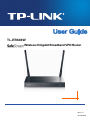
TL-ER604W
Wireless N Gigabit Broadband VPN Router
Rev1.0.1
1910010844
COPYRIGHT & TRADEMARKS
Specifications are subject to change without notice.
is a registered trademark of
TP-LINK TECHNOLOGIES CO., LTD. Other brands and product names are trademarks of their
respective holders.
No part of the specifications may be reproduced in any form or by any means or used to make any
derivative such as translation, transformation, or adaptation without permission from TP-LINK
TECHNOLOGIES CO., LTD. Copyright © 2013 TP-LINK TECHNOLOGIES CO., LTD. All rights
reserved.
http://www.tp-link.com
FCC STATEMENT
This equipment has been tested and found to comply with the limits for a Class A digital device,
pursuant to part 15 of the FCC Rules. These limits are designed to provide reasonable protection
against harmful interference when the equipment is operated in a commercial environment. This
equipment generates, uses, and can radiate radio frequency energy and, if not installed and used in
accordance with the instruction manual, may cause harmful interference to radio communications.
Operation of this equipment in a residential area is likely to cause harmful interference in which case
the user will be required to correct the interference at his own expense.
This device complies with part 15 of the FCC Rules. Operation is subject to the following two
conditions:
1)
This device may not cause harmful interference.
2)
This device must accept any interference received, including interference that may cause
undesired operation.
Any changes or modifications not expressly approved by the party responsible for compliance could
void the user’s authority to operate the equipment.
CE Mark Warning
This is a class A product. In a domestic environment, this product may cause radio interference, in
which case the user may be required to take adequate measures.
-I-
CONTENTS
Package Contents ..................................................................................................................1
Chapter 1 About this Guide ...................................................................................................2
1.1
Intended Readers ..................................................................................................................2
1.2
Conventions ...........................................................................................................................2
1.3
Overview of this Guide ...........................................................................................................2
Chapter 2 Introduction ..........................................................................................................3
2.1
Overview of the Router ..........................................................................................................3
2.2
Features.................................................................................................................................4
2.3
Appearance............................................................................................................................6
2.3.1
Front Panel ................................................................................................................6
2.3.2
Rear Panel.................................................................................................................7
Chapter 3 Configuration ........................................................................................................8
3.1
3.2
3.3
Network..................................................................................................................................8
3.1.1
Status.........................................................................................................................8
3.1.2
System Mode.............................................................................................................8
3.1.3
WAN ........................................................................................................................10
3.1.4
LAN..........................................................................................................................27
3.1.5
MAC Address...........................................................................................................30
3.1.6
Switch ......................................................................................................................31
Wireless ...............................................................................................................................37
3.2.1
Wireless Setting.......................................................................................................37
3.2.2
MAC Filtering ...........................................................................................................50
3.2.3
Host Status ..............................................................................................................51
User Group ..........................................................................................................................52
3.3.1
Group.......................................................................................................................52
3.3.2
User .........................................................................................................................53
3.3.3
View .........................................................................................................................54
-II-
3.4
3.5
3.6
3.7
3.8
Advanced .............................................................................................................................55
3.4.1
NAT..........................................................................................................................55
3.4.2
Traffic Control ..........................................................................................................63
3.4.3
Session Limit ...........................................................................................................66
3.4.4
Load Balance...........................................................................................................68
3.4.5
Routing ....................................................................................................................72
Firewall.................................................................................................................................77
3.5.1
Anti ARP Spoofing ...................................................................................................77
3.5.2
Attack Defense ........................................................................................................80
3.5.3
MAC Filtering ...........................................................................................................82
3.5.4
Access Control.........................................................................................................82
3.5.5
App Control..............................................................................................................88
VPN......................................................................................................................................89
3.6.1
IKE...........................................................................................................................90
3.6.2
IPsec........................................................................................................................94
3.6.3
L2TP/PPTP............................................................................................................100
Services .............................................................................................................................104
3.7.1
PPPoE Server........................................................................................................104
3.7.2
E-Bulletin ...............................................................................................................109
3.7.3
Dynamic DNS ........................................................................................................ 111
3.7.4
UPnP .....................................................................................................................116
Maintenance ......................................................................................................................117
3.8.1
Admin Setup ..........................................................................................................117
3.8.2
Management..........................................................................................................120
3.8.3
License ..................................................................................................................122
3.8.4
Statistics.................................................................................................................123
3.8.5
Diagnostics ............................................................................................................125
3.8.6
Time.......................................................................................................................127
-III-
3.8.7
Logs .......................................................................................................................128
Chapter 4 Application........................................................................................................130
4.1
Network Requirements.......................................................................................................130
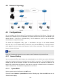
4.2
Network Topology...............................................................................................................131
4.3
Configurations....................................................................................................................131
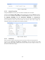
4.3.1
Internet Setting ......................................................................................................131
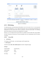
4.3.2
VPN Setting ...........................................................................................................133
4.3.3
Network Management............................................................................................139
4.3.4
Network Security....................................................................................................143
Appendix A
Hardware Specifications ...........................................................................148
Appendix B
FAQ .........................................................................................................149
Appendix C
Glossary ..................................................................................................151
-IV-
Package Contents
The following items should be found in your package:
One TL-ER604W Router
One Power Adapter
One RJ45 Ethernet Cable
Quick Installation Guide
Resource CD
Note:
Make sure that the package contains the above items. If any of the listed items is damaged or missing,
please contact with your distributor.
-1-
Chapter 1 About this Guide
This User Guide contains information for setup and management of TL-ER604W Router. Please read
this guide carefully before operation.
1.1 Intended Readers
This Guide is intended for Network Engineer and Network Administrator.
1.2 Conventions
In this Guide the following conventions are used:
The Router or TL-ER604W mentioned in this Guide stands for TL-ER604W SafeStream Wireless
N Gigabit Broadband VPN Router without any explanation.
Menu Name→Submenu Name→Tab page indicates the menu structure. Advanced→NAT
→Basic NAT means the Basic NAT page under the NAT menu option that is located under the
Advanced menu.
Bold font indicates a toolbar icon, menu or menu item.
<Font> indicate a button.
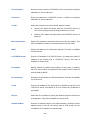
Symbols in this Guide:
Symbol
Description
Note: Ignoring this type of note might result in a malfunction or damage to the device.
Tips:
This format indicates important information that helps you make better use of your device.
1.3 Overview of this Guide
Chapter 1 About This Guide
Introduces the guide structure and conventions.
Chapter 2 Introduction
Introduces the features and appearance of this router.
Chapter 3 Configuration
Introduces how to configure the Router via Web management
page.
Chapter 4 Application
Introduces the practical application of the Router on the
enterprise network.
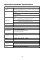
Appendix A Hardware Specifications
Lists the hardware specifications of this router.
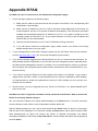
Appendix B FAQ
Provides the possible solutions to the problems that may
occur during the installation and operation of the router.
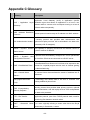
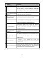
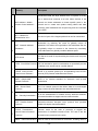
Appendix C Glossary
Lists the glossary used in this guide.
-2-
Chapter 2 Introduction
Thanks for choosing the SafeStream Wireless N Gigabit Broadband VPN Router TL-ER604W.
2.1 Overview of the Router
The SafeStream Wireless N Gigabit Broadband VPN Router TL-ER604W from TP-LINK supports
Wireless N speed and Gigabit wired speeds on all ports. It integrates multiple VPN protocols,
high-security and high-performance VPN capabilities, making it an ideal choice for branch offices in
need of cost-effective secure remote connections to headquarters or remote offices. Furthermore,
together with many useful features including hardware-based WiFi On/Off button, Guest Networking,
App Control, and PPPoE Server functions, TL-ER604W is an ideal network solution for home or small
office consumers.
Powerful Data Processing Capability
+ Built-in MIPS 32 network processor and 64MB DDRII high-speed RAM allows the stability and
reliability for operation.
Wireless Feature
+ Wireless N speed provides an incredible high speed experience.
+ Supporting Guest Networking feature, which provides a secure network for guests outside of the
existing, potentially sensitive LAN.
+ Hardware Wi-Fi On/Off button provides an easy way to turn wireless radio on or off
Virtual Private Network (VPN)
+ Providing comprehensive IPsec VPN with DES/3DES/AES encryptions, MD5/SHA1
identifications and automatically/manually IKE Pre-Share Key exchanges.
+ Supporting PPTP/L2TP VPN Server mode to allow the staff on business or remote branch office
to access the headquarter network.
Online Behavior Management
+ Complete Functions of Access Rules can allow managers to select the network service levels to
block or allow applications of FTP downloading, Email, Web browsing and so on.
+ Deploying One-Click restricting of IM/P2P applications to save time & energy while reserving
exceptional groups for certain users.
+ Supporting URL Filtering to prevent potential hazards from visiting the malicious Web sites.
Powerful Firewall
+ Supporting One-Click IP-MAC Binding to avoid ARP spoofing and guarantee a network without
stagnation.
+ Featured Attack Defense to protect the network from a variety of flood attack and packet
anomaly attack.
-3-
+ Possessing MAC Filtering function to block the access of illegal hosts.
Flexible Traffic Control
+ Featured Bandwidth Control with flexible bandwidth management to automatically control the
bandwidth of the host in bi-direction to avoid bandwidth over occupation, as well as optimize
bandwidth usage.
+ Supporting Session Limit to avoid the complaint of a few people to force whole sessions.
Dual-WAN Ports
+ Providing two 10/100/1000M WAN ports for users to connect two Internet lines for bandwidth
expansion.
+ Supporting multiple Load Balance modes, including Bandwidth Based Balance Routing,
Application Optimized Routing, and Policy Routing to optimize bandwidth usage.
+ Featured Link Backup to switch all the new sessions from dropped line automatically to another
for keeping an always on-line network.
Easy-to-use
+ Providing easy-to-use GUI with clear configuration steps and detailed help information for the
users to configure the Router simply.
+ Helping administrators to monitor the whole network status and take actions to malfunctions
according to the recorded log information.
+ Supporting remote management to manage the Router from remote places.
2.2 Features
Hardware
1 fixed gigabit WAN port, 1 interchangeable gigabit WAN/LAN port, 3 fixed gigabit LAN ports
Fanless Design for Quiet Operation
Hardware Wi-Fi On/Off button provides an easy way to turn wireless radio on or off
Supports Professional 4kV common mode lightning protection
Complies with IEEE 802.3, IEEE 802.3u, IEEE 802.3ab, IEEE 802.11 b/g/n standards
Supports AH, ESP, IKE, PPP protocols
Supports TCP/IP, DHCP, ICMP, NAT, NAPT protocols
Supports PPPoE, SNTP, HTTP, DDNS, UPnP, NTP protocols
Basic Functions
Supports Static IP, Dynamic IP, PPPoE/Russian PPPoE, L2TP/Russian L2TP, PPTP/Russian
PPTP, Dual Access, BigPond Internet connections
-4-
Supports Virtual Server, Port Triggering, ALG, Static Route and RIP v1/v2
Built-in Switch supporting Port Mirror, Port VLAN, Rate Control and so on
Supports to change the MAC address of LAN and WAN port
Supports Logs, Statistics, Time setting
Supports Remote and Web management
Supports Diagnostic (Ping/Tracert) and Online Detection
Wireless
Supports Wireless N speed and 2 detachable 5dBi antennas
Supports WEP, WPA/WPA2, WPA-PSK/WPA2-PSK Encryption
Supports WDS, Multi-SSID, Guest Network
VPN
Supports IPsec VPN and provides up to 30 IPsec VPN tunnels
Supports IPSec VPN in LAN-to-LAN or Client-to-LAN
Provides DES, 3DES, AES128, AES152, AES256 encryption, MD5, SHA1 authentication
Supports IKE Pre-Share Key and DH1/DH2/DH5 Key Exchanges
Supports PPTP/L2TP Server/Client
Traffic Control
Supports Bandwidth Control
Supports Session Limit
Security
Built-in firewall supporting URL/MAC Filtering
Supports Access Control
Supports Attack Defense
Supports IP-MAC Binding
Supports GARP (Gratuitous ARP)
Deploys One-Click restricting of IM/P2P applications
-5-
2.3 Appearance
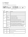
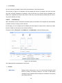
2.3.1 Front Panel
The front panel of TL-ER604W is shown as the following figure.
Figure 2-1 Front Panel
LEDs
LED
Status
Indication
On
The Router is powered on
Off
The Router is powered off or power supply is abnormal
Flashing
The Router works properly
On/Off
The Router works improperly
On(Green)
The wireless function is enabled
Off
The wireless function is disabled
PWR
SYS
WLAN
Flashing(Green) There is data being transferred through wireless
(Green/Yellow)
There is a device linked to the corresponding port but no activity.
(Green light indicates the linked device is running at 1000Mbps,
and yellow indicates the linked device is running at 10/100Mbps.)
Off
There is no device linked to the corresponding port
Flashing
The corresponding port is transmitting or receiving data. (Green
light indicates the linked device is running at 1000Mbps, and
yellow indicates the linked device is running at 10/100Mbps.)
On
WAN,LAN
(Green/Yellow)
Interface Description
Interface
Port
Description
WAN
1~2
The WAN port is for connecting the Router to a DSL/Cable modem or
Ethernet by the RJ45 cable
LAN
2~5
The LAN port is for connecting the Router to the local PCs or switches
by the RJ45 cable
-6-
Reset button
Use the button to restore the Router to the factory defaults. With the Router powered on, use a pin to
press and hold the Reset button (about 4~5 seconds). After the SYS LED goes out, release the Reset
button. If the SYS LED is flashing with a high frequency about two or three seconds, it means the Router
is restored successfully.
Wifi button
Press this button to enable or disable WI-FI.
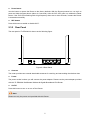
2.3.2 Rear Panel
The rear panel of TL-ER604W is shown as the following figure.
Figure 2-2 Rear Panel
Antenna
The router provides two external detachable antennas for receiving and transmitting the wireless data.
Power
The power socket is where you will connect the power adapter. Please use the power adapter provided
with this TL-ER604W SafeStream Wireless N Gigabit Broadband VPN Router.
On/Off
Press this button to turn on or turn off the Router.
Note:
Please use only the power cord provided with this Router.
-7-
Chapter 3 Configuration
3.1 Network
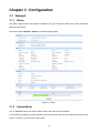
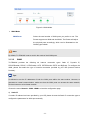
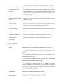
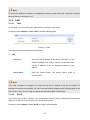
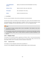
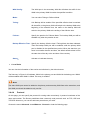
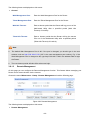
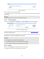
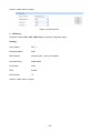
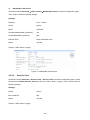
3.1.1 Status
The Status page shows the system information, the port connection status and other information
related to this Router.
Choose the menu Network→Status to load the following page.
Figure 3-1 Status
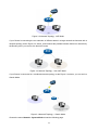
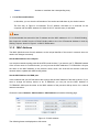
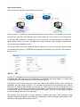
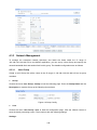
3.1.2 System Mode
The TL-ER604W Router can work in three modes: NAT, Non-NAT and Classic.
If your Router is hosting your local network’s connection to the Internet with a network topology as the
Figure 3-2 shown, you can set it to NAT mode.
-8-
Figure 3-2 Network Topology - NAT Mode
If your Router is connecting the two networks of different areas in a large network environment with a
network topology as the Figure 3-3 shown, and forwards the packets between these two networks by
the Routing rules, you can set it to Non-NAT mode.
Figure 3-3 Network Topology – Non-NAT Mode
If your Router is connected in a combined network topology as the Figure 3-4 shown, you can set it to
Classic Mode.
Figure 3-4 Network Topology – Classic Mode
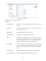
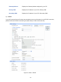
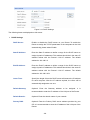
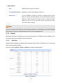
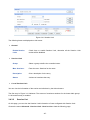
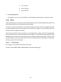
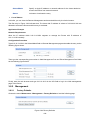
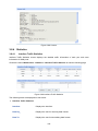
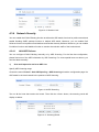
Choose the menu Network→System Mode to load the following page.
-9-
Figure 3-5 System Mode
You can select a System Mode for your Router according to your network need.
NAT Mode
NAT (Network Address Translation) mode allows the Router to translate private IP addresses within
internal networks to public IP addresses for traffic transport over external networks, such as the
Internet. Incoming traffic is translated back for delivery within the internal network. However, the
Router will drop all the packets whose source IP addresses are in different subnet of LAN port. For
example: If the LAN port of the Router is set to 192.168.0.1 for IP address and 255.255.255.0 for the
Subnet Mask, then the subnet of LAN port is 192.168.0.0/24. The packet with 192.168.0.123 as its
source IP address can be transported by NAT, whereas the packet with 20.31.76.80 as its source IP
address will be dropped.
Non-NAT Mode
In this mode, the Router functions as the traditional Gateway and forwards the packets via routing
protocol. The Hosts in different subnets can communicate with one another via the routing rules
whereas no NAT is employed.
Note:
In Non-NAT mode, all the NAT forwarding rules will be disabled.
Classic Mode
It's the combined mode of NAT mode and Non-NAT mode. In Classic mode, the Router will first
transport the packets which are compliant with NAT forwarding rules and then match the other packets
to the static routing rules. The matched packets will be transmitted based on the static routing rules
and the unmatched ones will be dropped. In this way, the Router can implement NAT for the packets
without blocking the packets in the different subnet of the ports.
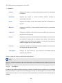
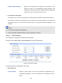
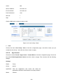
3.1.3 WAN
3.1.3.1
WAN Mode
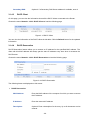
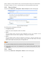
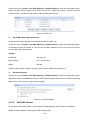
TL-ER604W provides two adjustable WAN ports. You can set the number of WAN ports on this page.
Choose the menu Network→WAN→WAN Mode to load the following page.
-10-
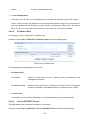
Figure 3-6 WAN Mode
WAN Mode
WAN Ports:
Select the total number of WAN ports you prefer to use. The
Router support one WAN and dual WAN. The Router will adjust
the physical ports accordingly, which can be illustrated on the
following port sketch.
Note:
By default, TL-ER604W is set to work in the mode of dual WAN ports.
3.1.3.2
WAN1
TL-ER604W provides the following six Internet connection types: Static IP, Dynamic IP,
PPPoE/Russian PPPoE, L2TP/Russian L2TP, PPTP/Russian PPTP and BigPond. To configure the
WAN, please first select the type of Internet connection provided by your ISP (Internet Service
Provider).
Tips:
It’s allowed to set the IP addresses of both the WAN ports within the same subnet. However, to
guarantee a normal communication, make sure that the WAN ports can access the same network,
such as Internet or a local area network.
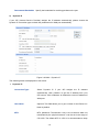
Choose the menu Network→WAN→WAN1 to load the configuration page.
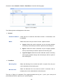
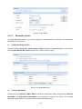
1)
Static IP
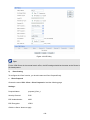
If a static IP address has been provided by your ISP, please choose the Static IP connection type to
configure the parameters for WAN port manually.
-11-
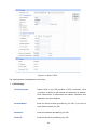
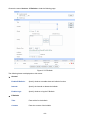
Figure 3-7 WAN – Static IP
The following items are displayed on this screen:
Static IP
Connection Type:
Select Static IP if your ISP has assigned a static IP address for your
computer.
IP Address:
Enter the IP address assigned by your ISP. If you are not clear,
please consult your ISP.
Subnet Mask:
Enter the Subnet Mask assigned by your ISP.
Default Gateway:
Optional. Enter the Gateway assigned by your ISP.
MTU:
MTU (Maximum Transmission Unit) is the maximum data unit
transmitted by the physical network. It can be set in the range of
576-1500. The default MTU is 1500. It is recommended to keep the
default value if no other MTU value is provided by your ISP.
Primary DNS:
Enter the IP address of your ISP’s Primary DNS (Domain Name
Server). If you are not clear, please consult your ISP. It’s not allowed
to access the Internet via domain name if the Primary DNS field is
blank.
Secondary DNS:
Optional. If a Secondary DNS Server address is available, enter it.
Upstream Bandwidth:
Specify the bandwidth for transmitting packets on the port.
-12-
Downstream Bandwidth: Specify the bandwidth for receiving packets on the port.
2)
Dynamic IP
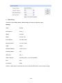
If your ISP (Internet Service Provider) assigns the IP address automatically, please choose the
Dynamic IP connection type to obtain the parameters for WAN port automatically.
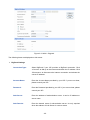
Figure 3-8 WAN – Dynamic IP
The following items are displayed on this screen:
Dynamic IP
Connection Type:
Select Dynamic IP if your ISP assigns the IP address
automatically. Click <Obtain> to get the IP address from your
ISP’s server. Click <Release> to release the current IP address of
WAN port.
Host Name:
Optional. This field allows you to give a name for the Router. It's
blank by default.
MTU:
MTU (Maximum Transmission Unit) is the maximum data unit
transmitted by the physical network. It can be set in the range of
576-1500. The default MTU is 1500. It is recommended to keep
-13-
the default value if no other MTU value is provided by your ISP.
Get IP Address by
The broadcast requirement may not be supported by a few ISPs.
Unicast:
Select this option if you can not get the IP address from your ISP
even if with a normal network connection. This option is not
required generally.
Use the following DNS
Select this option to enter the DNS (Domain Name Server)
Server:
address manually.
Primary DNS:
Enter the IP address of your ISP’s Primary DNS (Domain Name
Server). If you are not clear, please consult your ISP.
Optional. If a Secondary DNS Server address is available, enter
Secondary DNS:
it.
Upstream Bandwidth:
Specify the bandwidth for transmitting packets on the port.
Downstream
Specify the bandwidth for receiving packets on the port.
Bandwidth:
Dynamic IP Status
Status:
Displays the status of obtaining an IP address from your ISP.
“Disabled” indicates that the Dynamic IP connection type is not
applied.
“Connecting” indicates that the Router is obtaining the IP
parameters from your ISP.
“Connected” indicates that the Router has successfully
obtained the IP parameters from your ISP.
“Disconnected” indicates that the IP address has been
manually released or the request of the Router gets no response
from your ISP. Please check your network connection and consult
your ISP if this problem remains.
IP Address:
Displays the IP address assigned by your ISP.
Subnet Mask:
Displays the Subnet Mask assigned by your ISP.
-14-
3)
Gateway Address:
Displays the Gateway Address assigned by your ISP.
Primary DNS:
Displays the IP address of your ISP’s Primary DNS.
Secondary DNS:
Displays the IP address of your ISP’s Secondary DNS.
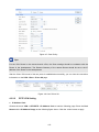
PPPoE
If your ISP (Internet Service Provider) has provided the account information for the PPPoE connection,
please choose the PPPoE connection type (Used mainly for DSL Internet service).
Figure 3-9 WAN - PPPoE
-15-
The following items are displayed on this screen:
PPPoE Settings
Connection Type:
Select PPPoE if your ISP provides xDSL Virtual Dial-up connection.
Click <Connect> to dial-up to the Internet and obtain the IP address.
Click <Disconnect> to disconnect the Internet connection and
release the current IP address.
Account Name:
Enter the Account Name provided by your ISP. If you are not clear,
please consult your ISP.
Password:
Enter the Password provided by your ISP.
Active Mode:
You can select the proper Active mode according to your need.
Manual: Select this option to manually activate or terminate the
Internet connection by the <Connect> or <Disconnect> button.
It is optimum for the dial-up connection charged on time.
Always-on: Select this option to keep the connection always
on. The connection can be re-established automatically when it
is down.
Time-based: Select this option to keep the connection on
during the Active time you set.
PPPoE Advanced
Check here to enable PPPoE advanced settings.
Settings:
Keep Alive:
Once PPPoE is connected, the Router will send keep-alive packets
every "Keep Alive Interval" sec and "Keep Alive Retry Times" to
make sure the connection is still alive. If the Router does not get the
response from ISP after sending keep-alive packets, then the
Router will terminate the connection.
MTU:
MTU (Maximum Transmission Unit) is the maximum data unit
transmitted by the physical network. It can be set in the range of
576-1492. The default MTU is 1480. It is recommended to keep the
default value if no other MTU value is provided by your ISP.
-16-
ISP Address:
Optional. Enter the ISP address provided by your ISP. It's null by
default.
Service Name:
Optional. Enter the Service Name provided by your ISP. It's null by
default.
Primary DNS:
Enter the IP address of your ISP’s Primary DNS.
Secondary DNS:
Optional. Enter the IP address of your ISP’s Secondary DNS.
Secondary Connection:
Here allows you to configure the secondary connection. Dynamic IP
and Static IP connection types are provided.
Connection Type:
Select the secondary connection type. Options include Disable,
Dynamic IP and Static IP.
IP Address:
If Static IP is selected, configure the IP address of WAN port. If
Dynamic IP is selected, the obtained IP address of WAN port is
displayed.
Subnet Address:
If Static IP is selected, configure the subnet address of WAN port. If
Dynamic IP is selected, the obtained subnet address of WAN port is
displayed.
Status:
Displays the status of secondary connection.
Upstream Bandwidth:
Specify the bandwidth for transmitting packets on the port.
Downstream Bandwidth:
Specify the bandwidth for receiving packets on the port.
PPPoE Status
Status:
Displays the status of PPPoE connection.
“Disabled” indicates that the PPPoE connection type is not
applied.
“Connecting” indicates that the Router is obtaining the IP
parameters from your ISP.
-17-
“Connected” indicates that the Router has successfully
obtained the IP parameters from your ISP.
“Disconnected” indicates that the connection has been
manually terminated or the request of the Router has no
response from your ISP. Please ensure that your settings are
correct and your network is connected well. Consult your ISP if
this problem remains.
4)
IP Address:
Displays the IP address assigned by your ISP.
Gateway Address:
Displays the Gateway Address assigned by your ISP.
Primary DNS:
Displays the IP address of your ISP’s Primary DNS.
Secondary DNS:
Displays the IP address of your ISP’s Secondary DNS.
L2TP
If your ISP (Internet Service Provider) has provided the account information for the L2TP connection,
please choose the L2TP connection type.
-18-
Figure 3-10 WAN - L2TP
The following items are displayed on this screen:
L2TP Settings
Connection Type:
Select L2TP if your ISP provides a L2TP connection. Click <Connect>
to dial-up to the Internet and obtain the IP address. Click
<Disconnect> to disconnect the Internet connection and release the
current IP address.
Account Name:
Enter the Account Name provided by your ISP. If you are not clear,
please consult your ISP.
Password:
Enter the Password provided by your ISP.
Server IP:
Enter the Server IP provided by your ISP.
-19-
MTU:
MTU (Maximum Transmission Unit) is the maximum data unit
transmitted by the physical network. It can be set in the range of
576-1460. The default MTU is 1460. It is recommended to keep the
default value if no other MTU value is provided by your ISP.
Active Mode:
You can select the proper Active Mode according to your need.
Manual: Select this option to manually activate or terminate the
Internet connection by the <Connect> or <Disconnect> button. It
is optimum for the dial-up connection charged on time.
Always-on: Select this option to keep the connection always on.
The connection can be re-established automatically when it is
down.
Secondary
Here allows you to configure the secondary connection. Dynamic IP
Connection:
and Static IP connection types are provided.
Connection Type:
Select the secondary connection type. Options include Disable,
Dynamic IP and Static IP.
IP Address:
If Static IP is selected, configure the IP address of WAN port. If
Dynamic IP is selected, the IP address of WAN port obtained is
displayed.
Subnet Mask:
If Static IP is selected, configure the subnet mask of WAN port. If
Dynamic IP is select, the subnet mask of WAN port obtained is
displayed.
Default Gateway:
If Static IP is selected, configure the default gateway. If Dynamic IP is
selected, the obtained default gateway is displayed.
Primary DNS/
If Static IP is selected, configure the DNS. If Dynamic IP is selected,
Secondary DNS:
the obtained DNS is displayed.
Upstream Bandwidth: Specify the bandwidth for transmitting packets on the port.
Downstream
Specify the bandwidth for receiving packets on the port.
Bandwidth:
-20-
L2TP Status
Status:
Displays the status of PPPoE connection.
“Disabled” indicates that the L2TP connection type is not applied.
“Connecting” indicates that the Router is obtaining the IP
parameters from your ISP.
“Connected” indicates that the Router has successfully obtained
the IP parameters from your ISP.
“Disconnected” indicates that the connection has been manually
terminated or the request of the Router has no response from
your ISP. Please ensure that your settings are correct and your
network is connected well. Consult your ISP if this problem
remains.
5)
IP Address:
Displays the IP address assigned by your ISP.
Primary DNS:
Displays the IP address of your ISP’s Primary DNS.
Secondary DNS:
Displays the IP address of your ISP’s Secondary DNS.
PPTP
If your ISP (Internet Service Provider) has provided the account information for the PPTP connection,
please choose the PPTP connection type.
-21-
Figure 3-11 WAN - PPTP
The following items are displayed on this screen:
PPTP Settings
Connection Type:
Select PPTP if your ISP provides a PPTP connection. Click
<Connect> to dial-up to the Internet and obtain the IP address.
Click <Disconnect> to disconnect the Internet connection and
release the current IP address.
Account Name:
Enter the Account Name provided by your ISP. If you are not
clear, please consult your ISP.
Password:
Enter the Password provided by your ISP.
Server IP:
Enter the Server IP provided by your ISP.
-22-
MTU:
MTU (Maximum Transmission Unit) is the maximum data unit
transmitted by the physical network. It can be set in the range of
576-1460. The default MTU is 1460. It is recommended to keep
the default value if no other MTU value is provided by your ISP.
Active Mode:
You can select the proper Active mode according to your need.
Manual: Select this option to manually activate or terminate
the Internet connection by the <Connect> or <Disconnect>
button. It’s optimum for the dial-up connection charged on
time.
Always-on: Select this option to keep the connection always
on. The connection can be re-established automatically
when it is down.
Secondary Connection:
Here allows you to configure the secondary connection.
Dynamic IP and Static IP connection types are provided.
Connection Type:
Select the secondary connection type. Options include Disable,
Dynamic IP and Static IP.
IP Address:
If Static IP is selected, configure the IP address of WAN port. If
Dynamic IP is selected, the IP address of WAN port obtained is
displayed.
Subnet Mask:
If Static IP is selected, configure the subnet mask of WAN port. If
Dynamic IP is select, the subnet mask of WAN port obtained is
displayed.
Default Gateway:
If Static IP is selected, configure the default gateway. If Dynamic
IP is selected, the obtained default gateway is displayed.
Primary DNS/
Secondary DNS:
If Static IP is selected, configure the DNS. If Dynamic IP is
selected, the obtained DNS is displayed.
Upstream Bandwidth:
Specify the bandwidth for transmitting packets on the port.
Downstream Bandwidth:
Specify the bandwidth for receiving packets on the port.
-23-
PPTP Status
Status:
Displays the status of PPTP connection.
“Disabled” indicates that the PPTP connection type is not
applied.
“Connecting” indicates that the Router is obtaining the IP
parameters from your ISP.
“Connected” indicates that the Router has successfully obtained
the IP parameters from your ISP.
“Disconnected” indicates that the connection has been manually
terminated or the request of the Router has no response from
your ISP. Please ensure that your settings are correct and your
network is connected well. Consult your ISP if this problem
remains.
6)
IP Address:
Displays the IP address assigned by your ISP.
Primary DNS:
Displays the IP address of your ISP’s Primary DNS.
Secondary DNS:
Displays the IP address of your ISP’s Secondary DNS.
BigPond
If your ISP (Internet Service Provider) has provided the account information for the BigPond
connection, please choose the BigPond connection type.
-24-
Figure 3-12 WAN – Bigpond
The following items are displayed on this screen:
BigPond Settings
Connection Type:
Select BigPond if your ISP provides a BigPond connection. Click
<Connect> to dial-up to the Internet and obtain the IP address. Click
<Disconnect> to disconnect the Internet connection and release the
current IP address.
Account Name:
Enter the Account Name provided by your ISP. If you are not clear,
please consult your ISP.
Password:
Enter the Password provided by your ISP. If you are not clear, please
consult your ISP.
Auth Server:
Enter the address of authentication server. It can be IP address or
server name.
Auth Domain:
Enter the domain name of authentication server. It's only required
when the address of Auth Server is a server name.
-25-
Auth Mode:
You can select the proper Active mode according to your need.
Manual: Select this option to manually activate or terminate the
Internet connection by the <Connect> or <Disconnect> button. It
is optimum for the dial-up connection charged on time.
Always-on: Select this option to keep the connection always on.
The connection can be re-established automatically when it is
down.
MTU:
MTU (Maximum Transmission Unit) is the maximum data unit
transmitted by the physical network. It can be set in the range of
576-1500. The default MTU is 1500.
Upstream/Downstream Specify the Upstream/Downstream Bandwidth for the port. To make
Bandwidth:
"Load Balance" and "Bandwidth Control" take effect, please set
these parameters correctly.
BigPond Status
Status:
Displays the status of BigPond connection.
“Disabled” indicates that the BigPond connection type is not
applied.
“Connecting” indicates that the Router is obtaining the IP
parameters from your ISP.
“Connected” indicates that the Router has successfully
obtained the IP parameters from your ISP.
“Disconnected” indicates that the connection has been
manually terminated or the request of the Router has no
response from your ISP. Please ensure that your settings are
correct and your network is connected well. Consult your ISP if
this problem remains.
IP Address:
Displays the IP address assigned by your ISP.
Subnet Mask:
Displays the Subnet Mask assigned by your ISP.
Default Gateway:
Displays the IP address of the default gateway assigned by your
ISP.
-26-
Note:
To ensure the BigPond connection re-established normally, please restart the connection at least 5
seconds after the connection is off.
3.1.4 LAN
3.1.4.1
LAN
On this page, you can configure the parameters for LAN port of this router.
Choose the menu Network→LAN→LAN to load the following page.
Figure 3-13 LAN
The following items are displayed on this screen:
LAN
IP Address:
Enter the LAN IP address of the Router. 192.168.0.1 is the
default IP address. The Hosts in LAN can access the Router
via this IP address. It can be changed according to your
network.
Subnet Mask:
Enter the Subnet Mask. The default subnet mask is
255.255.255.0.
Note:
If the LAN IP address is changed, you must use the new IP address to log into the Router. To
guarantee a normal communication, be sure to set the Gateway address and the Subnet Mask of the
Hosts on the LAN to the new LAN IP address and the Subnet Mask of the Router.
3.1.4.2
DHCP
The Router with its DHCP (Dynamic Host Configuration Protocol) server enabled can automatically
assign an IP address to the computers in the local area network.
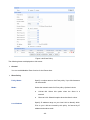
Choose the menu Network→LAN→DHCP to load the following page.
-27-
Figure 3-14 DHCP Settings
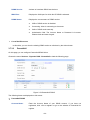
The following items are displayed on this screen:
DHCP Settings
DHCP Server:
Enable or disable the DHCP server on your Router. To enable the
Router to assign the TCP/IP parameters to the computers in the LAN
automatically, please select Enable.
Start IP Address:
Enter the Start IP address to define a range for the DHCP server to
assign dynamic IP addresses. This address should be in the same IP
address subnet with the Router’s LAN IP address. The default
address is 192.168.0.2.
End IP Address:
Enter the End IP address to define a range for the DHCP server to
assign dynamic IP addresses. This address should be in the same IP
address subnet with the Router’s LAN IP address. The default
address is 192.168.0.254.
Lease Time:
Specify the length of time the DHCP server will reserve the IP address
for each computer. After the IP address expired, the client will be
automatically assigned a new one.
Default Gateway:
Optional. Enter the Gateway address to be assigned. It is
recommended to enter the IP address of the LAN port of the Router.
Default Domain:
Optional. Enter the domain name of your network.
Primary DNS:
Optional. Enter the Primary DNS server address provided by your
ISP. It is recommended to enter the IP address of the LAN port of the
Router.
-28-
Secondary DNS:
3.1.4.3
Optional. If a Secondary DNS Server address is available, enter it.
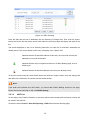
DHCP Client
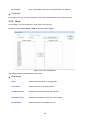
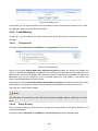
On this page, you can view the information about all the DHCP clients connected to the Router.
Choose the menu Network→LAN→DHCP Client to load the following page.
Figure 3-15 DHCP Client
You can view the information of the DHCP clients in this table. Click the Refresh button for the updated
information.
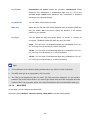
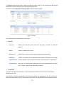
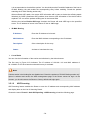
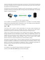
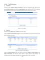
3.1.4.4
DHCP Reservation
DHCP Reservation feature allows you to reserve an IP address for the specified MAC address. The
client with this MAC address will always get the same IP address every time when it accesses the
DHCP server.
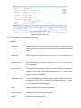
Choose the menu Network→LAN→DHCP Reservation to load the following page.
Figure 3-16 DHCP Reservation
The following items are displayed on this screen:
DHCP Reservation
MAC Address:
Enter the MAC address of the computer for which you want to reserve
the IP address.
IP Address:
Enter the reserved IP address.
Description:
Optional. Enter a description for the entry. Up to 28 characters can be
entered.
-29-
Status:
Activate or Inactivate the corresponding entry.
List of Reserved Address
In this table, you can view the information of the entries and edit them by the Action buttons.
The first entry in Figure 3-16 indicates: The IP address 192.168.0.101 is reserved for the
computer with the MAC address 00-19-66-83-53-CF, and this entry is activated.
Note:
It's recommended that users bind the IP address and the MAC address in 3.5.1.1 IP-MAC Binding ,
then import the entries from the IP-MAC binding table to the List of Reserved Address in buck by
clicking <Import> button in Figure 3-16 DHCP Reservation.
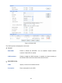
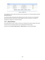
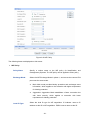
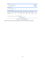
3.1.5 MAC Address
The MAC (Media Access Control) address, as the unique identifier of the router in network, does not
need to be changed commonly.
Set the MAC Address for LAN port:
In a complex network topology with all the ARP bound devices, if you want to use TL-ER604W instead
of the current router in a network node, you can just set the MAC address of TL-ER604W‘s LAN port
the same to the MAC address of the previous router, which can avoid all the devices under this
network node to update their ARP binding tables.
Set the MAC Address for WAN port:
In the condition that your ISP has bound the account and the MAC address of the dial-up device, if you
want to change the dial-up device to be TL-ER604W, you can just set the MAC address of
TL-ER604W’s WAN port the same to the MAC address of the previous dial-up device for a normal
Internet connection.
Choose the menu Network→MAC Address→MAC Address to load the following page.
Figure 3-17 MAC Address
The following items are displayed on this screen:
-30-
MAC Address
Displays the port type of the Router.
Port:
Current MAC Address: Displays the current MAC address of the port.
MAC Clone:
It’s only available for WAN port. Click the <Restore Factory MAC>
button to restore the MAC address to the factory default value or
click the <Clone Current PC’s MAC> button to clone the MAC
address of the PC you are currently using to configure the router.
Then click <Save> to apply.
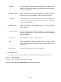
Note:
To avoid a conflict of MAC address on the local area network, it’s not allowed to set the MAC address
of the Router’s LAN port to the MAC address of the current management PC.
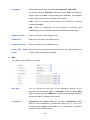
3.1.6 Switch
Some basic switch port management functions are provided by TL-ER604W, which facilitates you to
monitor the traffic and manage the network effectively.
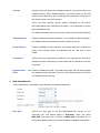
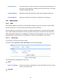
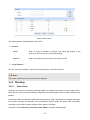
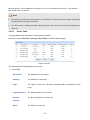
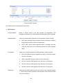
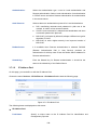
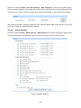
3.1.6.1
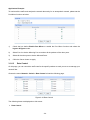
Statistics
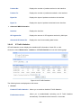
Statistics screen displays the detailed traffic information of each port, which allows you to monitor the
traffic and locate faults promptly.
Choose the menu Network→Switch→Statistics to load the following page.
Figure 3-18 Statistics
-31-
The following items are displayed on this screen:
Statistics
Unicast:
Displays the number of normal unicast packets received or transmitted
on the port.
Broadcast:
Displays the number of normal broadcast packets received or
transmitted on the port.
Pause:
Displays the number of flow control frames received or transmitted on
the port.
Multicast:
Displays the number of normal multicast packets received or transmitted
on the port.
Undersize:
Displays the number of the received frames (including error frames) that
are less than 64 bytes long.
Normal:
Displays the number of the received packets (including error frames) that
are between 64 bytes and the maximum frame length. The maximum
untagged frame this Router can support is 1518 bytes long and the
maximum tagged frame is 1522 bytes long.
Oversize:
Displays the number of the received packets (including error frames) that
are longer than the maximum frame.
Total (Bytes):
Displays the total number of the received or transmitted packets
(including error frames).
Click the <Clear All> button to clear all the traffic statistics.
Tips:
The Port 1/2/3/4/5 mentioned in this User Guide refers to the WAN1/2 port and LAN1/2/3 port on the
Router.
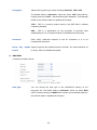
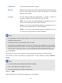
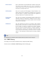
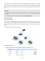
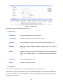
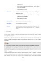
3.1.6.2
Port Mirror
Port Mirror, the packets obtaining technology, functions to forward copies of packets from one/multiple
ports (mirrored port) to a specific port (mirroring port). Usually, the mirroring port is connected to a data
diagnose device, which is used to analyze the mirrored packets for monitoring and troubleshooting the
network.
-32-
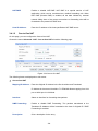
Choose the menu Network→Switch→Port Mirror to load the following page.
Figure 3-19 Port Mirror
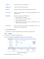
The following items are displayed on this screen:
General
Enable Port Mirror:
Check the box to enable the Port Mirror function. If unchecked, it will
be disabled.
Mode:
Select the mode for the port mirror function. Options include:
Ingress: When this mode is selected, only the incoming packets
received by the mirrored port will be copied to the mirroring port.
Egress: When this mode is selected, only the outgoing packets
sent by the mirrored port will be copied to the mirroring port.
Ingress & Egress: When this mode is selected, both the incoming
and outgoing packets through the mirrored port will be copied to
the mirroring port.
Port Mirror
Mirroring Port:
Select the Mirroring Port to which the traffic is copied. Only one port
can be selected as the mirroring port.
Mirrored Port:
Select the Mirrored Port from which the traffic is mirrored. One or
multiple ports can be selected as the mirrored ports.
The entry in Figure 3-19 indicates: The outgoing packets sent by port 1, port 2, port 3 and port 5
(mirrored ports) will be copied to port 4 (mirroring port).
-33-
Application Example:
To monitor all the traffic and analyze the network abnormity for an enterprise’s network, please set the
Port Mirror function as below:
1)
Check the box before Enable Port Mirror to enable the Port Mirror function and select the
Ingress & Egress mode.
2)
Select Port 3 to be the Mirroring Port to monitor all the packets of the other ports.
3)
Select all the other ports to be the Mirrored Ports.
4)
Click the <Save> button to apply.
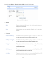
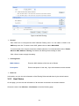
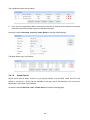
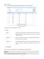
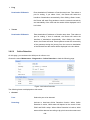
3.1.6.3
Rate Control
On this page, you can control the traffic rate for the specific packets on each port so as to manage your
network flow.
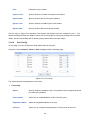
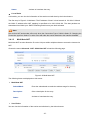
Choose the menu Network→Switch→Rate Control to load the following page.
Figure 3-20 Rate Control
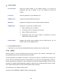
The following items are displayed on this screen:
Rate Control
-34-
Port:
Displays the port number.
Ingress Limit:
Specify whether to enable the Ingress Limit feature.
Ingress Rate:
Specify the limit rate for the ingress packets.
Egress Limit:
Specify whether to enable Egress Limit feature.
Egress Rate:
Specify the limit rate for the egress packets.
The first entry in Figure 3-20 indicates: The Ingress and Egress Limits are enabled for port 1. The
Ingress and Egress Rates are 1Mbps. That is, the receiving rate for the ingress packets will not exceed
1Mbps, and the transmitting rate for all the egress packets will not exceed 1Mbps.
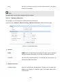
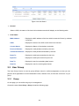
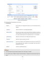
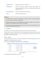
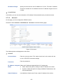
3.1.6.4
Port Config
On this page, you can configure the basic parameters for the ports.
Choose the menu Network→Switch→Port Config to load the following page.
Figure 3-21 Port Config
The following items are displayed on this screen:
Port Config
Status:
Specify whether to enable the port. The packets can be transported via this
port after being enabled.
Flow Control:
Allows you to enable/disable the Flow Control function.
Negotiation Mode:
Select the Negotiation Mode for the port.
All Ports:
Allows you to configure the parameters for all the ports at one time.
-35-
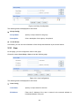
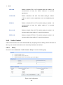
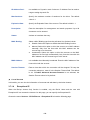
3.1.6.5
Port Status
On this page, you can view the current status of each port.
Choose the menu Network→Switch→Port Status to load the following page.
Figure 3-22 Port Status
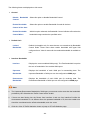
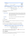
3.1.6.6
Port VLAN
A VLAN (Virtual Local Area Network) is a network topology configured according to a logical scheme
rather than the physical layout, which allows you to divide the physical LAN into multiple logical LANs
so as to control the communication among the ports.
The VLAN function can prevent the broadcast storm in LANs and enhance the network security. By
creating VLANs in a physical LAN, you can divide the LAN into multiple logical LANs, each of which
has a broadcast domain of its own. Hosts in the same VLAN communicate with one another as if they
are in a LAN. However, hosts in different VLANs cannot communicate with one another directly.
Therefore, broadcast packets are limited in a VLAN.
TL-ER604W provides the Port VLAN function, which allows you to create multiple logical VLANs for
the LAN ports based on their port numbers.
Choose the menu Network→Switch→Port VLAN to load the following page.
Figure 3-23 Port VLAN
The following items are displayed on this screen:
Port VLAN
Network:
Displays the current logical network of the physical port.
-36-
VLAN:
Select the desired VLAN for the port.
Tips:
The Port VLAN can only be created among the LAN ports.
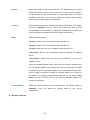
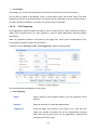
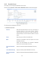
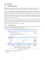
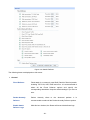
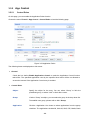
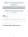
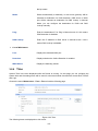
3.2 Wireless
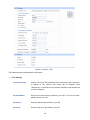
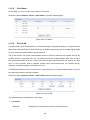
3.2.1 Wireless Setting
3.2.1.1
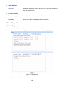
Wireless Setting
On this page you can configure the basic parameters of the wireless network.
Choose the menu Wireless→Wireless Setting→Wireless Setting to load the following page.
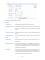
Figure 3-24 Wireless Setting
The following items are displayed on this screen:
Wireless Setting
Wireless:
Enable or disable the Wireless function.
-37-
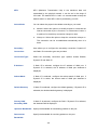
Region:
Select your region from the drop-down list. This field specifies the region
where the wireless function of the Router can be used. It may be illegal to
use the wireless function of the Router in a region other than one of those
specified in this field. If your country or region is not listed, please contact
your local government agency for assistance.
Channel:
This field determines which operating frequency will be used. The default
channel is automatic and the Router will choose the best channel
automatically. It is not necessary to change the wireless channel unless you
notice interference problems with another nearby access point.
Mode:
Select the desired mode.
11b only - Select if all of your wireless clients are 802.11b.
11g only - Select if all of your wireless clients are 802.11g.
11n only- Select only if all of your wireless clients are 802.11n.
11bg mixed - Select if you are using both 802.11b and 802.11g wireless
clients.
11bgn mixed - Select if you are using a mix of 802.11b, 11g, and 11n
wireless clients.
Select the desired wireless mode. When 802.11b mode is selected, only
802.11b wireless stations can connect to the Router. When 802.11g mode
is selected, only 802.11g wireless stations can connect to the Router. When
802.11n mode is selected, only 802.11n wireless stations can connect to
the Router. It is strongly recommended that you set the Mode 11bng
mixed, and all of 802.11b, 802.11g and 802.11n wireless stations can
connect to the Router.
Channel Width:
Select the channel width from the drop-down list. The default setting is
automatic, which can adjust the channel width for your clients
automatically.
Wireless Parameter
-38-
SSID:
Enter a name for the wireless network. The same name of SSID(Service
Set Identification) must be assigned to all wireless device in your network.
Considering your wireless network security, the default SSID is set to be
TP-LINK_XXXXXX (XXXXXX indicates the last unique six numbers of each
Router’s MAC address). This value is case-sensitive. For example, TEST is
NOT the same as test.
Description:
Enter the description for the SSID.
SSID Broadcast:
Enable or disable the SSID Broadcast. When wireless clients survey the
local area for wireless networks to associate with, they will detect the SSID
broadcast by the Router. If the SSID Broadcast is enabled, the Wireless
Router will broadcast its name (SSID) on the air.
AP Isolation
Enable or disable the AP Isolation. This function can isolate wireless
stations on your network from each other. Wireless devices will be able to
communicate with the Router but not with each other.
Security:
Specify the security option of the wireless network. If you do not want to use
wireless security, select “Disable Security”, otherwise select one Security
option from the drop-down list. It’s strongly recommended to choose one of
the security options to enable security.
There are three wireless security options supported by the Router:
WPA-PSK/WPA2-PSK, WPA/WPA2 and WEP. It is recommend to choose
WPA-PSK/WPA2-PSK.
The detail information of the three security options will be introduced below.
1)
WPA-PSK/WPA2-PSK
It’s the WPA/WPA2 authentication type based on pre-shared passphrase. The default security
option of the router is WPA-PSK/WPA2-PSK.
-39-
Auth Type:
Choose the Auth type of the WPA-PSK/WPA2-PSK security on the
drop-down list. The default setting is Automatic, which can select
WPA-PSK (Pre-shared key of WPA) or WPA2-PSK (Pre-shared key of
WPA) automatically based on the wireless station's capability and request.
Encryption:
Select the Encryption type, including Automatic, TKIP, AES.
The default setting is Automatic, which can select TKIP (Temporal Key
Integrity Protocol) or AES (Advanced Encryption Standard) automatically
based on the wireless station's capability and request.
TKIP – TKIP is a security protocol used in the IEEE 802.11 wireless
networking standard.
AES – AES is a specification for the encryption of electronic data
established by the U.S. National Institute of Standards and Technology.
Password:
Enter ASCII characters between 8 and 63 characters or 8 to 64
Hexadecimal characters. The default password is the same with the default
PIN code, which is labeled on the bottom of the Router
Group
Key
Period:
2)
Update Specify the group key update interval in seconds. The value should be 30
or above. Enter 0 to disable the update.
WPA/WPA2
It’s based on Radius Server.
Auth Type:
You can choose the Auth type of the WPA/WPA2 security on the
drop-down list. The default setting is Automatic, which can select WPA
(Wi-Fi Protected Access) or WPA2 (WPA version 2) automatically based on
the wireless station's capability and request.
-40-
Encryption:
Select the Encryption type. which including Automatic, TKIP, AES.
The default setting is Automatic, which can select TKIP (Temporal Key
Integrity Protocol) or AES (Advanced Encryption Standard) automatically
based on the wireless station's capability and request.
TKIP – TKIP is a security protocol used in the IEEE 802.11 wireless
networking standard.
AES – AES is a specification for the encryption of electronic data
established by the U.S. National Institute of Standards and Technology.
Radius Server IP:
Enter the IP address of the Radius server.
Radius Port:
Enter the port number of the Radius server.
Radius Password:
Enter the password for the Radius server.
Group
Key
Period:
3)
Update Specify the group key update interval in seconds. The value should be 30
or above. Enter 0 to disable the update.
WEP
It is based on the IEEE 802.11 standard.
Auth Type:
You can choose the Auth type of the WPA/WPA2 security on the
drop-down list. The default setting is Automatic, which can select WPA
(Wi-Fi Protected Access) or WPA2 (WPA version 2) automatically based on
the wireless station's capability and request.
-41-
Key Format:
Hexadecimal and ASCII formats are provided. Hexadecimal format
stands for any combination of hexadecimal digits (0-9, a-f, A-F) in the
specified length. ASCII format stands for any combination of keyboard
characters in the specified length.
Key Selected:
You can select the key based on need.
WEP Key:
Select which of the four keys will be used and enter the matching WEP key
that you create. Make sure these values are identical on all wireless
stations in your network.
Key Type:
You can select the WEP key length (64-bit, or 128-bit, or 152-bit.) for
encryption. "Disabled" means this WEP key entry is invalid.
64-bit - You can enter 10 hexadecimal digits (any combination of 0-9, a-f,
A-F, zero key is not promoted) or 5 ASCII characters.
128-bit - You can enter 26 hexadecimal digits (any combination of 0-9, a-f,
A-F, zero key is not promoted) or 13 ASCII characters.
152-bit - You can enter 32 hexadecimal digits (any combination of 0-9, a-f,
A-F, zero key is not promoted) or 16 ASCII characters.
Tips:
●
The modification of the Wireless Setting will take effect only after the router is rebooted.
●
The WEP Auth type is not supported by 802.11n mode.
●
The TKIP is not supported by 802.11n mode. The TKIP cannot be selected if 11n only mode is
selected. The router will not work in 11n mode if bgn mixed mode and TKIP encryption are both
selected. TKIP is an encryption option of the WPA-PSK/WPA2-PSK2 and WPA/WPA2 Auth type.
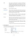
3.2.1.2
Multi-SSID
On this page you can configure the Multi-SSID..
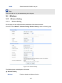
Choose the menu Wireless→Wireless Setting→Multi-SSID to load the following page.
-42-
Figure 3-25 Multi-SSID
The following items are displayed on this screen:
General
Multi-SSID:
Enable or disable the Multi-SSID. You can establish multiple wireless
networks if Multi-SSID is enabled.
SSID Insulation:
Enable or disable the SSID Insulation. If enabled, the hosts accessing to
the different SSID cannot be communicate with each other.
Multi-SSID Config
SSID:
Specify a name for the wireless network.
Description:
Enter a description for this SSID.
-43-
Specify the security option of the wireless network. If you do not want to use
Security:
wireless security, select “Disable Security”, otherwise select one Security
option from the drop-down list. It’s strongly recommended to choose one of
the security options to enable security.
There are three wireless security options supported by the Router:
WPA-PSK/WPA2-PSK, WPA/WPA2 and WEP. It is recommend to choose
WPA-PSK/WPA2-PSK.
The detail information of the three security options will be introduced below.
Enable or disable the SSID Broadcast. If you enable the SSID Broadcast ,
SSID Broadcast:
the Wireless Router will broadcast its name (SSID) on the air.
Enable or disable the Guest Network. If the Guest Network is enabled, the
Guest Network:
hosts in this network cannot communicate with the LAN port or other
SSIDs.
This function can isolate wireless stations on your network from each other.
AP Isolation:
Wireless devices will be able to communicate with the Router but not with
each other.
Enable/Disable
this Enable or disable this SSID. If you select this option, the host which passed
SSID
the validation will be allowed to connect to this SSID; otherwise, the Router
will refuse this host's request.
1)
WPA-PSK/WPA2-PSK
It’s the WPA/WPA2 authentication type based on pre-shared passphrase.
Auth Type:
Choose the Auth type of the WPA-PSK/WPA2-PSK security on the
drop-down list. The default setting is Automatic, which can select
WPA-PSK (Pre-shared key of WPA) or WPA2-PSK (Pre-shared key of
WPA) automatically based on the wireless station's capability and request.
-44-
Encryption:
Select the Encryption type, which including Automatic, TKIP, AES.
The default setting is Automatic, which can select TKIP (Temporal Key
Integrity Protocol) or AES (Advanced Encryption Standard) automatically
based on the wireless station's capability and request.
TKIP – TKIP is a security protocol used in the IEEE 802.11 wireless
networking standard.
AES – AES is a specification for the encryption of electronic data
established by the U.S. National Institute of Standards and Technology.
Password:
Enter ASCII characters between 8 and 63 characters or 8 to 64
Hexadecimal characters.
Group
Key
Period:
2)
Update Specify the group key update interval in seconds. The value should be 30
or above. Enter 0 to disable the update.
WPA/WPA2
It’s based on Radius Server.
Auth Type:
You can choose the Auth type of the WPA/WPA2 security on the
drop-down list. The default setting is Automatic, which can select WPA
(Wi-Fi Protected Access) or WPA2 (WPA version 2) automatically based on
the wireless station's capability and request.
-45-
Encryption:
Select the Encryption type. which including Automatic, TKIP, AES.
The default setting is Automatic, which can select TKIP (Temporal Key
Integrity Protocol) or AES (Advanced Encryption Standard) automatically
based on the wireless station's capability and request.
TKIP – TKIP is a security protocol used in the IEEE 802.11 wireless
networking standard.
AES – AES is a specification for the encryption of electronic data
established by the U.S. National Institute of Standards and Technology.
Radius Server IP:
Enter the IP address of the Radius server.
Radius Port:
Enter the port number of the Radius server.
Radius Password:
Enter the password for the Radius server.
Group
Key
Period:
3)
Update Specify the group key update interval in seconds. The value should be 30
or above. Enter 0 to disable the update.
WEP
It is based on the IEEE 802.11 standard.
Auth Type:
You can choose the Auth type of the WPA/WPA2 security on the
drop-down list. The default setting is Automatic, which can select WPA
(Wi-Fi Protected Access) or WPA2 (WPA version 2) automatically based on
the wireless station's capability and request.
Key Format:
Hexadecimal and ASCII formats are provided. Hexadecimal format
stands for any combination of hexadecimal digits (0-9, a-f, A-F) in the
specified length. ASCII format stands for any combination of keyboard
characters in the specified length.
-46-
Key Selected:
You can select the key based on need.
WEP Key:
Select which of the four keys will be used and enter the matching WEP key
that you create. Make sure these values are identical on all wireless
stations in your network.
Key Type:
You can select the WEP key length (64-bit, or 128-bit, or 152-bit.) for
encryption. "Disabled" means this WEP key entry is invalid.
64-bit - You can enter 10 hexadecimal digits (any combination of 0-9, a-f,
A-F, zero key is not promoted) or 5 ASCII characters.
128-bit - You can enter 26 hexadecimal digits (any combination of 0-9, a-f,
A-F, zero key is not promoted) or 13 ASCII characters.
152-bit - You can enter 32 hexadecimal digits (any combination of 0-9, a-f,
A-F, zero key is not promoted) or 16 ASCII characters.
Tips:
●
The parameters of the host which desires to connect to the router must be the same as the
parameter configured here.
●
The WEP Auth type is not supported by 802.11n mode.
●
The TKIP is not supported by 802.11n mode. The TKIP cannot be selected if 11n only mode is
selected. The router will not work in 11n mode If bgn mixed mode and TKIP encryption are both
selected. TKIP is a encryption option of the WPA-PSK/WPA2-PSK2 and WPA/WPA2 Auth type.
List of Group
In this table, you can view the information of the multi-SSID and edit them by the Action buttons.
The first entry in Figure 3-25 cannot be configured here. To edit it, please go to 3.2.1.1 Wireless
Setting.
Tips:
●
The WDS function will be disabled if Multi-SSID is enabled.
●
UP to 7 new SSIDs can be added to the router.
●
The router allows only one SSID to use WEP Auth.
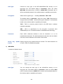
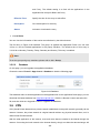
3.2.1.3
WDS
With the WDS function, the Router can bridge two or more WLANs.
-47-
Choose the menu Wireless→Wireless Setting→WDS to load the following page.
Figure 3-26 WDS Configuration
General
WDS:
Enable or disable the WDS function. With this function, the Router can
bridge two or more WLANs.
Scan:
Click this button; you can search the AP which runs in the current
channel.
Parameter
SSID(to be bridged):
The SSID of the AP your Router is going to connect to as a client. You
can also use the search function to select the SSID to join.
BSSID(to be bridged):
The BSSID of the AP your Router is going to connect to as a client. You
can also use the search function to select the BSSID to join.
Key Type:
This option should be chosen according to the AP's security
configuration. It is recommended that the security type is the same as
your AP's security type
WEP Key Index:
This option should be chosen if the key type is WEP (ASCII) or WEP
(HEX).It indicates the index of the WEP key.
Auth Type:
This option should be chosen if the key type is WEP (ASCII) or WEP
(HEX).It indicates the authorization type of the Root AP.
-48-
Key:
If the AP your Router is going to connect needs password, you need to
fill the key in this blank.
Tips:
The Multi-SSID function will be disabled if WDS is enabled.
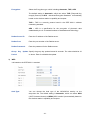
3.2.1.4
Wireless Advanced
On this page, you can configure the wireless advanced parameters.
Choose the menu Wireless→Wireless Setting→Wireless Advanced to load the following page.
Figure 3-27 Wireless Advanced
General
WMM:
WMM function can guarantee the packets with high- priority messages
being transmitted preferentially. It is strongly recommended enabled.
Short GI:
This function is recommended for it will increase the data capacity by
reducing the guard interval time.
Wireless Advanced
Transmit Power:
Here you can specify the transmit power of Router. You can select High,
Middle or Low which you would like. High is the default setting and is
recommended.
-49-
Beacon Interval:
Enter a value between 40-1000 milliseconds for Beacon Interval here.
The beacons are the packets sent by the router to synchronize a
wireless network. Beacon Interval value determines the time interval of
the beacons. The default value is 100.
RTS Threshold:
Here you can specify the RTS (Request to Send) Threshold. If the
packet is larger than the specified RTS Threshold size, the router will
send RTS frames to a particular receiving station and negotiate the
sending of a data frame. The default value is 2346.
Fragmentation
This value is the maximum size determining whether packets will be
Threshold:
fragmented. Setting the Fragmentation Threshold too low may result in
poor network performance since excessive packets. 2346 is the default
setting and is recommended.
DTIM Interval:
This value determines the interval of the Delivery Traffic Indication
Message (DTIM). A DTIM field is a countdown field informing clients of
the next window for listening to broadcast and multicast messages.
When the Router has buffered broadcast or multicast messages for
associated clients, it sends the next DTIM with a DTIM Interval value.
You can specify the value between 1-255 Beacon Intervals. The default
value is 1, which indicates the DTIM Interval is the same as Beacon
Interval.
Tips:
The modification of the Wireless Advanced will take effect only after the router is rebooted.
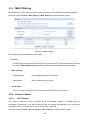
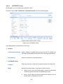
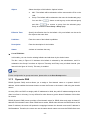
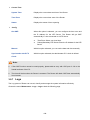
3.2.2 MAC Filtering
On this page, you can control the wireless access by configuring the MAC Filtering.
Choose the menu User Wireless→MAC Filtering to load the following page.
-50-
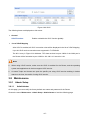
Figure 3-28 MAC Filtering
General
Each SSID can be configured the MAC Address Filtering rules. You can select a SSID in the
SSID drop-down list. To create a new SSID, please refer to 3.2.1.2 Multi-SSID.
To control some of the hosts to access the wireless network, it is recommended to select “Enable
Wireless MAC Address Filtering” and select one filtering rule according to need.
Click <Save> button to apply the setting.
Filtering Rules
MAC Address:
Enter the MAC Address of the host to be filtered.
Description:
Enter a description for the entry. Up to 28 characters can be entered.
Rule List
In this table, you can view the information of the Filtering Rules and edit them by the Action buttons.
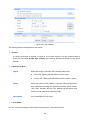
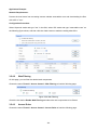
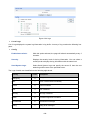
3.2.3 Host Status
On this page, you can view the information of all the hosts connected to the wireless network.
Choose the menu User Wireless→Host Status to load the following page.
-51-
Figure 3-29 Host Status
General
Select a SSID, the status of the host in this wireless network will display on the following table.
Host Status
MAC Address:
Displays the MAC address of the host which access the Router by wireless
connection.
SSID:
Displays the name of the SSID to which the host connects.
Current Status:
Displays the Status of the wireless connection.
Received Packets:
Displays the total packets received by the host.
Transmitted Packets: Displays the total packets transmitted by the host.
Bytes Tx:
Displays the total bytes transmitted by the host.
Bytes Rx:
Displays the total bytes received by the host.
Rate Tx:
Displays the rate for transmitting data frames.
Rate Rx:
Displays the rate for receiving data frames.
3.3 User Group
The User Group function is used to group different users for unified management, so that you can
perform other applications such as Bandwidth Control, Session Limit, and Access Control etc. on per
group.
3.3.1 Group
On this page you can define the group for management.
Choose the menu User Group→Group to load the following page.
-52-
Figure 3-30 Group Configuration
The following items are displayed on this screen:
Group Config
Group Name:
Specify a unique name for the group.
Description:
Give a description for the group. It's optional.
List of Group
In this table, you can view the information of the Groups and edit them by the Action buttons.
3.3.2 User
On this page, you can configure the User for the group.
Choose the menu User Group→User to load the following page.
Figure 3-31 User Configuration
The following items are displayed on this screen:
User Config
User Name:
Specify a unique name for the user.
IP Address:
Enter the IP Address of the user. It cannot be the network address or
broadcast address of the port.
-53-
Description:
Give a description to the user for identification. It's optional.
List of User
In this table, you can view the information of the Users and edit them by the Action buttons.
3.3.3 View
On this page, you can configure the User View or Group View.
Choose the menu User Group→View to load the following page.
Figure 3-32 View Configuration
The following items are displayed on this screen:
View Config
View:
Select the desired view for configuration.
User Name:
Select the name of the desired User.
Available Group:
Displays the Groups that the User can join.
Selected Group:
Displays the Groups to which this User belongs.
Group Name:
Select the name of the desired Group.
-54-
Group Structure:
Click this button to view the tree structure of this group. All the members of
this group will be displayed, including Users and sub-Groups. The Group
Names are displayed in bold.
Available Member:
Displays the Users and the Groups which can be added into this group.
Selected Member:
Displays the members of this group, including Users and Groups.
3.4 Advanced
3.4.1 NAT
NAT (Network Address Translation) is the translation between private IP and public IP, which allows
private network users to visit the public network using private IP addresses.
With the explosion of the Internet, the number of available IP addresses is not enough. NAT provides a
way to allow multiple private hosts to access the public network with one public IP at the same time,
which alleviates the shortage of IP addresses. Furthermore, NAT strengthens the LAN (Local Area
Network) security of the network since the address of LAN host never appears on the Internet.
3.4.1.1
NAT Setup
On this page, you can set up the NAT function.
Choose the menu Advanced→NAT→NAT Setup to load the following page.
Figure 3-33 NAT Setup
The following items are displayed on this screen:
NAPT
Source Port Range:
Enter the source port range between 2049 and 65000, the span of which
must be not less than 100.
NAT-DMZ
-55-
NAT-DMZ:
Enable or disable NAT-DMZ. NAT DMZ is a special service of NAT
application, which can be considered as a default forwarding rule. When
NAT DMZ (Pseudo DMZ) is enabled, all the data initiated by external
network falling short of the current connections or forwarding rules will be
forwarded to the preset NAT DMZ host.
Host IP Address:
3.4.1.2
Enter the IP address of the host specified as NAT DMZ server.
One-to-One NAT
On this page, you can configure the One-to-One NAT.
Choose the menu Advanced→NAT→One-to-One NAT to load the following page.
Figure 3-34 One to One NAT
The following items are displayed on this screen:
One-to-One NAT
Mapping IP Address: Enter the Original IP Address in the first checkbox and Translated
IP Address in the second checkbox. TL-ER604W allows mapping from LAN
port to WAN port in LAN Mode.
Interface:
Select an interface for forwarding data packets.
DMZ Forwarding:
Enable or disable DMZ Forwarding. The packets transmitted to the
Translated IP Address will be forwarded to the host of Original IP if DMZ
Forwarding is enabled.
Description:
Give a description for the entry.
-56-
Activate or inactivate the entry.
Status:
List of Rules
In this table, you can view the information of the entries and edit them by the Action buttons.
The first entry in Figure 3-34 indicates: The IP address of host1 in local network is 192.168.0.128 and
the WAN IP address after NAT mapping is specified to be 222.135.48.128. The data packets are
transmitted from WAN1 port. DMZ Forwarding and this entry are both activated.
Note:
One-to-One NAT entries take effect only when the Connection Type of WAN is Static IP. Changing the
Connection type from Static IP to other ones will make the entries attached to the interface disabled.
3.4.1.3
Multi-Nets NAT
Multi-Nets NAT function allows the IP under LAN port within multiple subnets to access the Internet via
NAT.
Choose the menu Advanced→NAT→Multi-Nets NAT to load the following page.
Figure 3-35 Multi-Nets NAT
The following items are displayed on this screen:
Multi-Nets NAT
Subnet/Mask:
Enter the subnet/mask to make the address range for the entry.
Description:
Give a description for the entry.
Status:
Activate or inactivate the entry.
list of Rules
You can view the information of the entries and edit them by the Action buttons.
-57-
The first entry in Figure 3-35 indicates that: This is a Multi-Nets NAT entry named tplink1. The subnet
under the LAN port of the Router is 192.168.2.0/24 and this entry is activated. After the corresponding
Static Route entry is set, the hosts within this subnet can access the Internet through the Router via
NAT.
Note:
●
Multi-Nets NAT entry takes effect only when cooperating with the corresponding Static Route
entries.
●
For detailed setting of subnet mask, please refer to the Appendix BFAQ
Application Example:
Network Requirements
The LAN subnet of TL-ER604W is 192.168.0.0 /24, the subnet of VLAN2 under a three layer switch is
192.168.2.0 /24, while the subnet of VLAN3 is 192.168.3.0 /24. The IP of VLAN for cascading the
switch to the Router is 192.168.0.2. Now the hosts within VLAN2 and VLAN3 desire to access the
Internet.
The network topology is shown as the following:
Configuration procedure
1.
Establish the Multi-Nets NAT entries with Subnet/Mask of VLAN2 and VLAN3.
-58-
The configured entries are as follows:
2.
Then set the corresponding Static Route entry, enter the IP address of the interface connecting
the Router and the three layer switch into the Next Hop field.
Choose the menu Advanced→Routing→Static Route to load the following page.
The Static Route entry is as follows:
3.4.1.4
Virtual Server
Virtual server sets up public services in your private network, such as DNS, Email and FTP, and
defines a service port. All the service requests to this port will be transmitted to the LAN server
appointed by the Router via IP address.
Choose the menu Advanced→NAT→Virtual Server to load the following page.
-59-
Figure 3-36 Virtual Server
The following items are displayed on this screen:
Virtual Server
Name:
Enter a name for Virtual Server entries. Up to 28 characters can be
entered.
Interface:
Select an interface for forwarding data packets.
External Port:
Enter the service port or port range the Router provided for accessing
external network. All the requests from Internet to this service port or
port range will be redirected to the specified server in local network.
Internal Port:
Specify the service port of the LAN host as virtual server.
Protocol:
Specify the protocol used for the entry.
Internal Server IP:
Enter the IP address of the specified internal server for the entry. All
the requests from the Internet to the specified LAN port will be
redirected to this host.
Status:
Activate or inactivate the entry.
Note:
●
The External port and Internal Port should be set in the range of 1-65535.
●
The external ports of different entries should be different, whereas the internal ports can be the
same.
-60-
List of Rules
In this table, you can view the information of the entries and edit them by the Action buttons.
The first entry in Figure 3-36 indicates: This is a Virtual Server entry named host, all the TCP data
packets from WAN1 to port 65534-65535 of the Router will be redirected to the port 65534-65535 of
the LAN host with IP address of 192.168.0.103, and this entry is activated.
3.4.1.5
Port Triggering
Some applications require multiple connections, such as Internet games, video conferencing, Internet
calling, P2P download and so on. Port Triggering is used for those applications requiring multiple
connections.
When an application initiates a connection to the trigger port, all the ports corresponding to the
incoming port will open for follow-up connections.
Choose the menu Advanced→NAT→Port Triggering to load the following page.
Figure 3-37 Port Triggering
The following items are displayed on this screen:
Port Triggering
Name:
Enter a name for Port Triggering entries. Up to 28 characters can be
entered.
Interface:
Select an interface for forwarding data packets.
Trigger Port:
Enter the trigger port number or the range of port. Only when the
trigger port initiates connection will all the corresponding incoming
ports open and provide service for the applications, otherwise the
incoming ports will not open.
-61-
Trigger Protocol:
Select the protocol used for trigger port.
Incoming Port:
Enter the incoming port number or range of port numbers. The
incoming port will open for follow-up connection after the trigger port
initiates connection.
Incoming Protocol:
Select the protocol used for incoming port.
Status:
Activate or inactivate the entry.
Note:
●
The Trigger Port and Incoming Port should be set in the range of 1-65535. The Incoming Port can
be set in a continuous range such as 8690-8696.
●
The Router supports up to 16 Port Triggering entries. Each entry supports at most 5 groups of
trigger ports and overlapping between the ports is not allowed.
●
Each entry supports at most 5 groups of incoming ports and the sum of incoming ports you set for
each entry should not be more than 100.
List of Rules
In this table, you can view the information of the entries and edit them by the Action buttons.
The first entry in Figure 3-37 indicates that: This is a Port Triggering entry named host1, When the LAN
host initiates a TCP request via port of 5354, the incoming port 5355 of WAN1 will open for TCP and
UDP protocol. This entry is activated.
3.4.1.6
ALG
Some special protocols such as FTP, H.323, SIP, IPsec and PPTP will work properly only when ALG
(Application Layer Gateway) service is enabled.
Choose the menu Advanced→NAT→ALG to load the following page.
Figure 3-38 ALG
The following items are displayed on this screen:
-62-
ALG
FTP ALG:
Enable or disable FTP ALG. The default setting is enabled. It is
recommended to keep the default setting if no special
requirement.
H.323 ALG:
Enable or disable H.323 ALG. The default setting is enabled.
H.323 is used for various applications such as NetMeeting and
VoIP.
SIP ALG:
Enable or disable SIP ALG. The default setting is enabled. It is
recommended to keep the default setting if no special
requirement.
IPsec ALG:
Enable or disable IPsec ALG. The default setting is enabled. It is
recommended to keep default if no special requirement.
PPTP ALG:
Enable or disable PPTP ALG. The default setting is enabled. It is
recommended to keep default if no special requirement.
3.4.2 Traffic Control
Traffic Control functions to control the bandwidth by configuring rules for limiting various data flows. In
this way, the network bandwidth can be reasonably distributed and utilized.
3.4.2.1
Setup
Choose the menu Advanced→Traffic Control→Setup to load the following page.
Figure 3-39 Configuration
-63-
The following items are displayed on this screen:
General
Disable Bandwidth
Select this option to disable Bandwidth Control.
Control:
Enable Bandwidth
Select this option to enable Bandwidth Control all the time.
Control all the time:
Enable Bandwidth
With this option selected, the Bandwidth Control will take effect when the
Control When:
bandwidth usage reaches the specified value.
Default Limit
Limited
Default Limit applies only for users that are not constrained by Bandwidth
Bandwidth:
Control Rules. These users share certain bandwidth with upper limit
configured here. Value 0 means all the remained bandwidth is available to
use.
Interface Bandwidth
Interface:
Displays the current enabled WAN port(s). The Total bandwidth is equal to
the sum of bandwidth of the enabled WAN ports.
Upstream
Displays the bandwidth of each WAN port for transmitting data. The
Bandwidth:
Upstream Bandwidth of WAN port can be configured on WAN page.
Downstream
Displays the bandwidth of each WAN port for receiving data. The
Bandwidth:
Downstream Bandwidth of WAN port can be configured on WAN page.
Note:
●
The Upstream/Downstream Bandwidth of WAN port you set must not be more than the bandwidth
provided by ISP. Otherwise the Traffic Control will be invalid.
●
If there are data flowing into the Router from interface A and out from interface B while the
downstream bandwidth of A is different from the upstream bandwidth of B, then the smaller one
should be considered as the effective bandwidth, and vice versa.
●
Click the <View IP Traffic Statistics> button to jump to IP Traffic Statistics page.
-64-
3.4.2.2
Bandwidth Control
On this page, you can configure the Bandwidth Control function.
Choose the menu Advanced→Traffic Control→Bandwidth Control to load the following page.
Figure 3-40 Bandwidth Control
The following items are displayed on this screen:
Bandwidth Control Rule
Direction:
Select the data stream direction for the entry. The direction of
arrowhead indicates the data stream direction. WAN-ALL
means all WAN ports through which the data flow might pass.
Individual WAN port cannot be selected if WAN-ALL rules are
added.
Group:
Select the group to define the controlled users.
Mode:
Individual: The bandwidth of each user equals to the current
bandwidth of this entry.
Shared: The total bandwidth of all controlled IP addresses
equals to the current bandwidth of this entry.
Guaranteed Bandwidth
Specify the Guaranteed Upstream Bandwidth for this entry.
(Up):
Limited Bandwidth (Up):
Specify the Limited Upstream Bandwidth for this entry.
Guaranteed Bandwidth
Specify the Guaranteed Downstream Bandwidth for this entry.
(Down):
-65-
Limited Bandwidth
Specify the Limited Downstream Bandwidth for this entry.
(Down):
Effective Time:
Specify the time for the entry to take effect.
Description:
Give a description for the entry.
Status:
Activate or inactivate the entry.
List of Rules
You can view the information of the entries and edit them by the Action buttons.
The first entry in Figure 3-40 indicates: The users within group “group1” share the bandwidth and the
Downstream/Upstream Guaranteed Bandwidth is 5000kbps, while the Downstream/Upstream Limited
bandwidth is 10000kbps. This entry takes effect at 8 a.m. to 10 p.m. from Monday to Friday.
Note:
●
The premise for single rule taking effect is that the bandwidth of the interface for this rule is
sufficient and not used up.
●
It is impossible to satisfy all the guaranteed bandwidth if the total guaranteed bandwidth specified
by all Bandwidth Control rules for certain interface exceeds the physical bandwidth of this
interface.
3.4.3 Session Limit
The amount of TCP and UDP sessions supported by the Router is finite. If some local hosts transmit
too many TCP and UDP sessions to the public network, the communication quality of the other local
hosts will be affected, thus it is necessary to limit the sessions of those hosts.
3.4.3.1
Session Limit
On this page, you can configure the session limit to specified PCs.
Choose the menu Advanced→Session Limit→Session Limit to load the following page.
-66-
Figure 3-41 Session Limit
The following items are displayed on this screen:
General
Enable Session
Check here to enable Session Limit, otherwise all the Session Limit
Limit:
entries will be disabled.
Session Limit
Group:
Select a group to define the controlled users.
Max. Sessions:
Enter the max. Sessions for the users.
Description:
Give a description for the entry.
Status:
Activate or inactivate the entry.
List of Session Limit
You can view the information of the entries and edit them by the Action buttons.
The first entry in Figure 3-41 indicates: The amount of maximum sessions for the hosts within group1
is 100 and this entry is enabled.
3.4.3.2
Session List
On this page, you can view the Session Limit information of hosts configured with Session Limit.
Choose the menu Advanced→Session Limit→Session List to load the following page.
-67-
Figure 3-42 Session List
In this table, you can view the session limit information of users configured with Session Limit. Click
the <Refresh> button to get the latest information.
3.4.4 Load Balance
In this part, you can configure the traffic sharing mode of the WAN ports to optimize the resource
utilization.
3.4.4.1
Configuration
Choose the menu Advanced→Load Balance→Configuration to load the following page.
Figure 3-43 Configuration
With the box before Enable Application Optimized Routing checked, the Router will consider the
source IP address and destination IP address of the packets as a whole and record the WAN port they
pass through. And then the packets with the same source IP address and destination IP address or
destination port will be forwarded to the recorded WAN port. This feature is to ensure the
multi-connected applications to work properly.
Check the box before Enable Bandwidth Based Balance Routing and select the WAN port below,
Load Balance of the specified WAN port will be enabled automatically if no routing rules are set.
Then click the <Save> button to apply.
Note:
The WAN ports not connecting to the Internet don’t support Intelligent Balance, please do not select
them.
3.4.4.2
Policy Routing
Policy Routing provides an accurate way to control the routing based on the policy defined by the
network administrator.
Choose the menu Advanced→Load Balance→Policy Routing to load the following page.
-68-
Figure 3-44 Policy Routing
The following items are displayed on this screen:
General
Protocol:
Select the protocol for the entry in the drop-down list. If the protocol you
want to set is not in the list, you can add it to the list on 3.4.4.4 Protocol
page.
Source IP:
Enter the source IP range for the entry. 0.0.0.0 - 0.0.0.0 means any IP is
acceptable.
Destination IP:
Enter the destination IP range for the entry. 0.0.0.0 - 0.0.0.0 means any
IP is acceptable.
Source Port:
Enter the source Port range for the entry, which is effective only when the
protocol is TCP, UDP or TCP/UDP. The default value is 1 – 65535, which
means any port is acceptable.
Destination Port:
Enter the destination port range for the entry, which is effective only when
the protocol is TCP, UDP or TCP/UDP. The default value is 1 – 65535,
which means any port is acceptable.
WAN:
Select the WAN port for transmitting packets.
Effective Time:
Specify the time for the entry to take effect.
Status:
Activate or inactivate the entry.
-69-
List of Rules
You can view the information of the entries and edit them by the Action buttons.
The first entry in Figure 3-44 indicates: All the packets with Source IP between 192.168.0.100 and
192.168.0.199 and Destination IP between 116.10.20.28 and 116.10.20.29 will be forwarded from
WAN1 port, regardless of the port and protocol. This entry is activated d and will take effect at 8 am to
10 pm from Monday to Friday.
3.4.4.3
Link Backup
With Link Backup function, the Router will switch all the new sessions from dropped line automatically
to another to keep an always on-line network.
On this page, you can configure the Link Backup function based on actual need to reduce the traffic
burden of WAN port and improve the network efficiency.
Choose the menu Advanced→Load Balance→Link Backup to load the following page.
Figure 3-45 Link Backup
The following items are displayed on this screen:
General
WAN Ports:
Displays all the WAN ports in use. You can drag the light-blue WAN
button to primary and backup WAN list. The color of WAN button
changing to gray indicates that the WAN port is already in the primary
and backup WAN list.
-70-
WAN Config:
The WAN port in the secondary WAN list will share the traffic for the
WAN in the primary WAN list under the specified condition.
Mode:
You can select Timing or Failover Mode.
Timing:
Link Backup will be enabled if the specified effective time is reached.
All the traffic on the primary WAN will switch to the backup WAN at the
beginning of the effective time; the traffic on the backup WAN will
switch to the primary WAN at the ending of the effective time.
Failover:
Specify the premise for Failover Mode. The backup WAN port will be
enabled only when the premise is met.
Backup Effective Time: Specify the backup effective time if Timing Mode has been selected.
Then the backup WAN port will be enabled, while the primary WAN
port is disabled in the specified time period. When the start time you
enter is not earlier than the end time, the default effective time is from
the start time of the day to the end time of the next day.
Status:
Activate or inactivate the entry.
List of Rules
You can view the information of the entries and edit them by the Action buttons.
The first entry in Figure 3-45 indicates: WAN1 is the primary port and WAN2 is the backup port. WAN2
will be enabled while WAN1 is failed. This entry is enabled.
Note:
The same WAN port cannot be added to the primary and secondary WAN lists at the same time, and
one WAN port should be added to only one list.
3.4.4.4
Protocol
On this page, you can specify the protocol for routing rules conveniently. A protocol constitutes of the
name and number. The Router predefines three commonly used protocols such as TCP, UDP and
TCP/UDP. Moreover, you can also add new protocols as your wish.
Choose the menu Advanced→Load Balance→Protocol to load the following page.
-71-
Figure 3-46 Protocol
The following items are displayed on this screen:
Protocol
Name:
Enter a name to indicate a protocol. The name will display in the
drop-down list of Protocol on Access Rule page.
Number:
Enter the Number of the protocol in the range of 0-255.
List of Protocol
You can view the information of the entries and edit them by the Action buttons.
Note:
The system predefined protocols cannot be configured.
3.4.5 Routing
3.4.5.1
Static Route
Routing is the process of selecting optimized paths in a network along which to send network traffic.
Static Route is a kind of special routing configured by the administrator, which is simple, efficient, and
reliable.
Commonly used in small-sized network with fixed topology, Static Route does not change along with
the network topology automatically. The administrator should modify the static route information
manually as long as the network topology or link status is changed.
Choose the menu Advanced→Routing→Static Route to load the following page.
-72-
Figure 3-47 Static Route
The following items are displayed on this screen:
Static Route
Destination:
Enter the destination host the route leads to.
Subnet Mask:
Enter the Subnet Mask of the destination network.
Next Hop:
Enter the gateway IP address to which the packet should be sent next.
Interface:
Select the physical network interface, through which this route is
accessible.
Metric:
Defines the priority of the route. The smaller the value is, the higher the
priority is. The default value is 0. It is recommended to keep the default
value.
Description:
Give a description for the entry.
Status:
Activate or inactivate the entry.
List of Rules
You can view the information of the entries and edit them by the Action buttons.
The first entry in Figure 3-47 indicates: If there are packets being sent to a device with IP address of
211.162.1.0 and subnet mask of 255.255.255.0, the Router will forward the packets from WAN1 port to
the next hop of 211.200.1.1.
-73-
Application Example
There is a network topology as the following figure shown:
If the LAN port of TL-ER604W(with Non-NAT or Classic system mode)is connected to LAN1 with
subnet of 192.168.0.0/24, while the LAN port of another Router R1 is connected to LAN2 with network
of 192.168.2.0/24. Meanwhile, the WAN ports of the two routers are interconnected and within the
same network. Now a host under TL-ER604W and within network of LAN1 desires to communicate
with the host within network of LAN2.
You can set a Static Route entry: Enter the WAN IP address of R1 (116.31.88.16) in the Next Hop field
on the Static Route page of TL-ER604W as the following figure shown, then click the <Add> button to
save the entry.
3.4.5.2
RIP
RIP (Routing Information Protocol) is a dynamic route protocol using distance vector algorithm to select
the optimal path. With features of easy configuration, management and implementation, it is widely used
in small and medium-sized networks such as the campus network.
The distance of RIP refers to the hop counts that a data packet passes through before reaching its
destination, the value range of which is 1–15. It means the destination cannot be reached if the value is
more than 15. Optimal path indicates the path with the fewest hop counts. RIP exchanges the route
information every 30 seconds by broadcasting UDP packets. If one Router has not sent route information
in 180 seconds, the RIP of the other routers would set the distance to this Router into infinity and delete
the corresponding information from route table.
RIP develops from initial RIPv1 to RIPv2 gradually. Compared with RIPv1, RIPv2 supports VLSM
(Variable Length Subnet Mask), simple plain text authentication, MD5 cryptograph authentication, CIDR
(Classless Inter-Domain Routing) and multicast.
-74-
TL-ER604W supports both RIPv1 version and RIPv2 version, thus you can configure the RIP version
based on the actual need to improve the network performance.
Choose the menu Advanced→Routing→RIP to load the following page.
Figure 3-48 RIP
The following items are displayed on this screen:
General
Interface:
Displays the interfaces which has been physically connected or assigned
static IP.
Status:
Enable or disable RIP protocol.
RIP Version:
Select RIPv1 or RIPv2. RIPv2 supports multicast and broadcast.
Password
If RIPv2 is enabled, set the Password Authentication according to the actual
Authentication: network situation, and the password should not be more than 15 characters.
All Interfaces:
Here you can operate all the interfaces in bulk. All the interfaces will not apply
RIP if “Enable” option for All Interfaces is selected.
List of RIP
After RIP is enabled, the information of RIP forwarding the packets received by the Router will be
displayed in the list.
The first entry in Figure 3-48 indicates: when receiving packets with destination IP is 116.10.20.28, the
Router will select WAN1 which is in the same network with the destination IP as next hop and forward
-75-
data via this port. The IP address of next hop is 116.10.1.254 and the hop count is 1. The effective
time of this entry is 1 second.
Note:
●
RIP function cannot be set if the Router is in NAT Mode. To set RIP function, please change the
System Mode to Routing or Full Mode.
●
The RIP function of WAN port takes effects only when the Connection Type of this WAN port is
Static IP.
3.4.5.3
Route Table
This page displays the information of the system route table.
Choose the menu Advanced→Routing→Route Table to load the following page.
Figure 3-49 RIP
The following items are displayed on this screen:
Route Table
Destination:
The Destination of route entry.
Gateway:
The Gateway of route entry.
Flags:
The Flags of route entry. The Flags describe certain characteristics of the
route.
Logical Interface:
The logical interface of route entry.
Physical
The physical interface of route entry.
Interface:
Metric
The Metric of route entry.
-76-
3.5 Firewall
3.5.1 Anti ARP Spoofing
ARP (Address Resolution Protocol) is used for analyzing and mapping IP addresses to the
corresponding MAC addresses so that packets can be delivered to their destinations correctly.
ARP functions to translate the IP address into the corresponding MAC address and maintain an ARP
Table in which the latest used IP address-to-MAC address mapping entries are stored. ARP protocol
can facilitate the Hosts in the same network segment to communicate with one another or access to
external network via Gateway. However, since ARP protocol is implemented with the premise that all
the Hosts and Gateways are trusted, there are high security risks during ARP Implementation
Procedure in the actual complex network.
The attacker may send the ARP spoofing packets with false IP address-to-MAC address mapping
entries, and then the device will automatically update the ARP table after receiving wrong ARP
packets, which results in a breakdown of the normal communication. Thus, ARP defense technology is
generated to prevent the network from this kind of attack.
3.5.1.1
IP-MAC Binding
IP-MAC Binding functions to bind the IP address, MAC address of the host together and only allows the
Hosts matching the bound entries to access the network.
Choose the menu Firewall→Anti ARP Spoofing→IP-MAC Binding to load the following page.
Figure 3-50 IP-MAC Binding
The following items are displayed on this screen:
General
-77-
It is recommended to check all the options. You should import the IP and MAC address of the host to
IP-MAC Binding List and enable the corresponding entry before enabling “Permit the packets
matching the IP-MAC Binding entries only”.
When suffered ARP attack, the correct ARP information will be sent to the device suffering attack
initiatively by GARP (Gratuitous ARP) packets, thus the error ARP information of the device will be
replaced. You can set the packets sending rate in the Interval field.
With the box before Enable ARP Logs checked, the Router will send ARP logs to the specified
server. The IP address of server is the Server IP set on 3.8.7 Logs.
IP-MAC Binding
IP Address:
Enter the IP Address to be bound.
MAC Address:
Enter the MAC Address corresponding to the IP Address.
Description:
Give a description for the entry.
Status:
Activate or inactivate the entry.
List of Rules
You can view the information of the entries and edit them by the Action buttons.
The first entry in Figure 3-50 indicates: The IP address of 192.168.1.101 and MAC address of
00-19-66-83-53-CF have been bound and this entry is activated.
Note:
If all the entries in the binding list are disabled and “Permit the packets of IP-MAC Binding entries only”
option is selected and saved, the WEB management page of the Router cannot be login. At the
moment, you should restore the Router to factory default and login again.
3.5.1.2
ARP Scanning
ARP Scanning feature enables the Router to scan the IP address and corresponding MAC address
and display them on the List of Scanning Result.
Choose the menu Firewall→Anti ARP Spoofing→ARP Scanning to load the following page.
-78-
Figure 3-51 ARP Scanning
Enter the start and the end IP addresses into the Scanning IP Range field. Then click the <Scan>
button, the Router will scan all the active hosts within the scanning range and display the result in the
list.
The entries displayed on the List of Scanning Result do not mean the IP and MAC addresses are
already bound. The current status for the entry will display in the “Status” field.
---
Indicates that the IP and MAC address of this entry are not bound and may be
replaced by error ARP information.
Indicates that this entry is imported to the list on IP-MAC Binding page, but not
effective yet.
Indicates that the IP and MAC address of this entry are already bound.
To bind the entries in the list, check these entries and click the <Import> button, then the settings will
take effect if the entries do not conflict with the existed entries.
Note:
If the local hosts suffered from ARP attack, you cannot add IP-MAC Binding entries on this page.
Please add entries manually on 3.5.1.1 IP-MAC Binding.
3.5.1.3
ARP List
On this page, the IP-MAC information of the hosts which communicated with the Router recently will
be saved in the ARP list.
Choose the menu Firewall→Anti ARP Spoofing→ARP List to load the following page.
-79-
Figure 3-52 ARP List
The configurations for the entries is the same as the configuration of List of Scanning Result on 3.5.1.2
ARP Scanning page.
The unbound IP-MAC information will be replaced by new IP-MAC information or be automatically
removed from the list if it has not been communicated with others for a long time. This period is
regarded as the aging time of the ARP information.
3.5.2 Attack Defense
With Attack Defense function enabled, the Router can distinguish the malicious packets and prevent
the port scanning from external network, so as to guarantee the network security.
Choose the menu Firewall→Attack Defense→Attack Defense to load the following page.
-80-
Figure 3-53 Attack Defense
The following items are displayed on this screen:
General
Flood Defense:
Flood attack is a commonly used DoS (Denial of Service) attack,
including TCP SYN, UDP, ICMP and so on. It is recommended to
select
all
the
Flood
Defense
options
and
specify
the
corresponding thresholds. Keep the default settings if you are not
sure.
Packet Anomaly
Packet
Anomaly
refers
Defense:
recommended to select all the Packet Anomaly Defense options.
Enable Attack
With this box checked, the Router will record the defense logs.
Defense Logs:
-81-
to
the
abnormal
packets.
It
is
3.5.3 MAC Filtering
On this page, you can control the Internet access of local hosts by specifying their MAC addresses.
Choose the menu Firewall→MAC Filtering→MAC Filtering to load the following page.
Figure 3-54 MAC Filtering
The following items are displayed on this screen:
General
To control the access to Internet for hosts in you private network, it is recommended to check the
box before Enable MAC Filtering and select a filtering mode according to actual situation.
MAC Filtering
MAC Address:
Enter the MAC Address to be filtered.
Description:
Give a description for the entry.
List of Rules
You can view the information of the entries and edit them by the Action buttons.
3.5.4 Access Control
3.5.4.1
URL Filtering
URL (Uniform Resource Locator) specifies where an identified resource is available and the
mechanism for retrieving it. URL Filter functions to filter the Internet URL address, so as to provide a
convenient way for controlling the access to Internet from LAN hosts.
Choose the menu Firewall→Access Control→URL Filtering to load the following page.
-82-
Figure 3-55 URL Filtering
The following items are displayed on this screen:
General
To control the access to Internet for hosts in your private network, you are recommended to
check the box before Enable URL Filtering and select a filtering rule based on the actual
situation.
URL Filtering Rule
Object:
Mode:
Select the range in which the URL Filtering takes effect:
ANY: URL Filtering will take effect to all the users.
Group: URL Filtering will take effect to all the users in group.
Select the mode for URL Filtering. “Keyword’’ indicates that all the
URL addresses including the specified keywords will be filtered.
“URL Path” indicates that the URL address will be filtered only
when it exactly matches the specified URL.
Description:
Give a description for the entry.
List of Rules
You can view the information of the entries and edit them by the Action buttons.
-83-
Application Example:
Network Requirements:
Prevent the local hosts from accessing Internet website www.aabbcc.com and downloading the files
with suffix of “exe”.
Configuration Procedure:
Select Keywords mode and type ”exe“ in the field, select URL mode and type “www.aabbcc.com” as
the following figure shows, and then click the <Add> button to make the setting take effect.
3.5.4.2
Web Filtering
On this page, you can filter the desired web components.
Choose the menu Firewall→Access Control→Web Filtering to load the following page.
Figure 3-56 Web Filtering
Check the box before Enable Web Filtering and select the web components to be filtered.
3.5.4.3
Access Rules
Choose the menu Firewall→Access Control→Access Rules to load the following page.
-84-
Figure 3-57 Access Rule
The following items are displayed on this screen:
Access Rules
Policy:
Select a policy for the entry:
Block: When this option is selected, the packets obeyed the
rule will not be permitted to pass through the Router.
Allow: When this option is selected, the packets obeyed the
rule will be allowed to pass through the Router.
Service:
Select the service for the entry. Only the service belonging to the
specified service type is limited by the entry. For example, if you
select “Block” for Policy and only FTP for Service, the packets of
other service types can still pass through the Router. You can add
new service types on 3.5.4.4 Service.
Interface:
Select interface for the entry. The entry will take effect when the
interface to which the data is flowing is selected. WAN and LAN
refers to all the WAN and LAN interfaces.
Source:
Select the Source IP Range for the entries, including the following
three ways:
IP/MASK: Enter an IP address or subnet mask. ("0.0.0.0/32"
-85-
means any IP).
Group: Select a predefined group of users. You can set the
group on3.3.1 Group.
Destination:
ANY: means for any users.
Select the Destination IP Range for the entries, including the
following two ways:
IP/MASK: Enter an IP address or subnet mask. ("0.0.0.0/32"
means any IP is acceptable).
ANY: means for any users.
Effective Time:
Specify the time for the entry to take effect.
Description:
Give a description for the entry.
Priority:
Select this option to specify the priority for the added entries. The
latest enabled entry will be displayed at the end of the list by
default.
List of Rules
You can view the information of the entries and edit them by the Action buttons. The smaller the value
is, the higher the priority is.
The first entry in Figure 3-57 indicates: The TELNET packets transmitted from the hosts within the
network of 192.168.0.0/24 will be not allowed to pass through the Router at 8:00-20:00 from Tuesday
to Saturday.
Note:
●
For the users in the private network and not being set access rule, the default Policy is Allow.
●
To specify all IP addresses, type “0.0.0.0 / 32” in the Policy field.
●
For detailed setting of subnet mask, please refer to Appendix B
3.5.4.4
FAQ.
Service
The Service function allows you to specify the protocol and port number to be filtered for Firewall
function conveniently. Protocol name and port range constitute a service type. The Router predefines
three commonly used services such as HTTP, FTP and TELNET and you can also add customized
-86-
services if needed.
Choose the menu Firewall→Access Control→Service to load the following page.
Figure 3-58 Service
The following items are displayed on this screen:
Service
Name:
Enter a name for the service. The name should not be more than 28
characters. The name will display in the drop-down list of Protocol on
Access Rule page.
Protocol:
Select the protocol for the service. The system predefined protocols
include TCP, UDP and TCP/UDP.
Dest. Port:
Enter the start and end ports to make a destination port range for the
service. The start port number cannot be greater than the end port
number.
List of Service
You can view the information of the entries and edit them by the Action buttons.
Note:
The service types predefined by the system cannot be modified.
-87-
3.5.5 App Control
3.5.5.1
Control Rules
On this page, you can enable the Application Rules function.
Choose the menu Firewall→App Control→Control Rules to load the following page.
Figure 3-59 Application Rules
The following items are displayed on this screen:
General
Check the box before Enable Application Control to make the Application Control function
take effect. The specified application used by the specified local users will be not allowed to
access the Internet if the Application Control entry is enabled.
Control Rules
Object:
Specify the object for the entry. You can select “Group” to limit the
predefined group, or select “ANY” to limit all the users.
Group:
If select “Group” as object, you can select the group in the drop-down list.
To establish new group, please refer to 3.3.1 Group.
Application:
Click the <Application List> button to select applications from the popup
checkbox. The applications include IM, Web IM, SNS, P2P, Media, Basic
-88-
and Proxy. The default setting is to limit all the applications in the
application list except for Basic and Proxy.
Effective Time:
Specify the time for the entry to take effect.
Description:
Give a description for the entry.
Status:
Activate or inactivate the entry.
List of Rules
You can view the information of the entries and edit them by the Action buttons.
The first entry in Figure 3-59 indicates: The group1 is applied with Application Rules. You can click
<View> to view the limited applications in the popup checkbox. The effective time of this entry is
7:00-9:00 on Monday, Tuesday, Friday, Saturday and Sunday. This entry is enabled.
Note:
To set the group and group members, please refer to 3.3.1 Group.
3.5.5.2
Database
On this page, you can upgrade the application database.
Choose the menu Firewall→App Control→Database to load the following page.
Figure 3-60 Database
The database refers to all the applications in the application list on the Application Rules page, you can
download the latest database from http://www.tp-link.com, Click the <Browse> button and select the
file, and then click the <Upgrade> button to upgrade the database.
3.6 VPN
VPN (Virtual Private Network) is a private network established via the public network, generally via the
Internet. However, the private network is a logical network without any physical network lines, so it is
called Virtual Private Network.
With the wide application of the Internet, more and more data are needed to be shared through the
Internet. Connecting the local network to the Internet directly, though can allow the data exchange, will
-89-
cause the private data to be exposed to all the users on the Internet. The VPN (Virtual Private Network)
technology is developed and used to establish the private network through the public network, which
can guarantee a secured data exchange.
VPN adopts the tunneling technology to establish a private connection between two endpoints. It is a
connection secured by encrypting the data and using point-to-point authentication. The following
diagram is a typical VPN topology.
Figure 3-61 VPN – Network Topology
As the packets are encapsulated and de-encapsulated in the Router, the tunneling topology
implemented by encapsulating packets is transparent to users. The tunneling protocols supported by
TL-ER604W contain Layer 3 IPsec and Layer 2 L2TP/PPTP.
3.6.1 IKE
In the IPsec VPN, to ensure a secure communication, the two peers should encapsulate and
de-encapsulate the packets using the information both known. Therefore the two peers need to
negotiate a security key for communication with IKE (Internet Key Exchange) protocols.
Actually IKE is a hybrid protocol based on three underlying security protocols, ISAKMP (Internet
Security Association and Key Management Protocol), Oakley Key Determination Protocol, and
SKEME Security Key Exchange Protocol. ISAKMP provides a framework for Key Exchange and SA
(Security Association) negotiation. Oakley describes a series of key exchange modes. SKEME
describes another key exchange mode different from those described by Oakley.
IKE consists of two phases. Phase 1 is used to negotiate the parameters, key exchange algorithm and
encryption to establish an ISAKMP SA for securely exchanging more information in Phase 2. During
phase 2, the IKE peers use the ISAKMP SA established in Phase 1 to negotiate the parameters for
security protocols in IPsec and create IPsec SA to secure the transmission data.
3.6.1.1
IKE Policy
On this page you can configure the related parameters for IKE negotiation.
Choose the menu VPN→IKE→IKE Policy to load the following page.
-90-
Figure 3-62 IKE Policy
The following items are displayed on this screen:
IKE Policy
Policy Name:
Specify a unique name to the IKE policy for identification and
management purposes. The IKE policy can be applied to IPsec policy.
Exchange Mode:
Select the IKE Exchange Mode in phase 1, and ensure the remote VPN
peer uses the same mode.
Main: Main mode provides identity protection and exchanges more
information, which applies to the scenarios with higher requirement
for identity protection.
Aggressive: Aggressive Mode establishes a faster connection but
with lower security, which applies to scenarios with lower
requirement for identity protection.
Local ID Type:
Select the local ID type for IKE negotiation. IP Address: uses an IP
address as the ID in IKE negotiation. FQDN: uses a name as the ID.
-91-
Local ID:
The local WAN IP will be inputted automatically if IP Address type is
selected. If Name type is selected, enter a name for the local device as
the ID in IKE negotiation
Remote ID Type:
Select the remote ID type for IKE negotiation. IP Address: uses an IP
address as the ID in IKE negotiation. FQDN: uses a name as the ID.
Remote ID:
The remote gateway IP will be inputted automatically if IP Address type
is selected. If Name type is selected, enter the name of the remote peer
as the ID in IKE negotiation.
IKE Proposal:
Select the Proposal for IKE negotiation phase 1. Up to four proposals
can be selected.
Pre-shared Key:
Enter the Pre-shared Key for IKE authentication, and ensure both the
two peers use the same key. The key should consist of visible characters
without blank space.
SA Lifetime:
Specify ISAKMP SA Lifetime in IKE negotiation.
DPD:
Enable or disable DPD (Dead Peer Detect) function. If enabled, the IKE
endpoint can send a DPD request to the peer to inspect whether the IKE
peer is alive.
DPD Interval:
Enter the interval after which the DPD is triggered.
List of IKE Policy
In this table, you can view the information of IKE Policies and edit them by the action buttons.
3.6.1.2
IKE Proposal
On this page, you can define and edit the IKE Proposal.
Choose the menu VPN→IKE→IKE Proposal to load the following page.
-92-
Figure 3-63 IKE Proposal
The following items are displayed on this screen:
IKE Proposal
Proposal Name:
Specify a unique name to the IKE proposal for identification and
management purposes. The IKE proposal can be applied to IPsec proposal.
Authentication:
Select the authentication algorithm for IKE negotiation. Options include:
MD5: MD5 (Message Digest Algorithm) takes a message of arbitrary
length and generates a 128-bit message digest.
SHA1: SHA1 (Secure Hash Algorithm) takes a message less than
2^64 (the 64th power of 2) in bits and generates a 160-bit message
digest.
Encryption:
Specify the encryption algorithm for IKE negotiation. Options include:
DES: DES (Data Encryption Standard) encrypts a 64-bit block of plain
text with a 56-bit key.
DH Group:
3DES: Triple DES, encrypts a plain text with 168-bit key.
AES128: Uses the AES algorithm and 128-bit key for encryption.
AES192: Uses the AES algorithm and 192-bit key for encryption.
AES256: Uses the AES algorithm and 256-bit key for encryption.
Select the DH (Diffie-Hellman) group to be used in key negotiation phase
1. The DH Group sets the strength of the algorithm in bits. Options include
DH1, DH2 and DH5.
-93-
DH1: 768 bits
DH2: 1024 bits
DH3: 1536 bits
List of IKE Proposal
In this table, you can view the information of IKE Proposals and edit them by the action buttons.
3.6.2 IPsec
IPsec (IP Security) is a set of services and protocols defined by IETF (Internet Engineering Task Force)
to provide high security for IP packets and prevent attacks.
To ensure a secured communication, the two IPsec peers use IPsec protocol to negotiate the data
encryption algorithm and the security protocols for checking the integrity of the transmission data, and
exchange the key to data de-encryption.
IPsec has two important security protocols, AH (Authentication Header) and ESP (Encapsulating
Security Payload). AH is used to guarantee the data integrity. If the packet has been tampered during
transmission, the receiver will drop this packet when validating the data integrity. ESP is used to check
the data integrity and encrypt the packets. Even if the encrypted packet is intercepted, the third party
still cannot get the actual information.
3.6.2.1
IPsec Policy
On this page, you can define and edit the IPsec policy.
Choose the menu VPN→IPsec→IPsec Policy to load the following page.
-94-
Figure 3-64 IPsec Policy
The following items are displayed on this screen:
General
You can enable/disable IPsec function for the Router here.
IPsec Policy
Policy Name:
Specify a unique name to the IPsec policy. Up to 28 characters
can be entered.
Mode:
Select the network mode for IPsec policy. Options include:
LAN-to-LAN: Select this option when the client is a
network.
Local Subnet:
Client-to-LAN: Select this option when the client is a host.
Specify IP address range on your local LAN to identify which
PCs on your LAN are covered by this policy. It's formed by IP
address and subnet mask.
-95-
Remote Subnet:
Specify IP address range on your remote network to identify
which PCs on the remote network are covered by this policy. It's
formed by IP address and subnet mask.
WAN:
Specify the local WAN port for this Policy. The "Remote
Gateway" of the remote peer should be set to the IP address of
this WAN port.
Remote Gateway:
Enter the Remote Gateway. It can be IP address or Domain
name.
Policy Mode:
Select the negotiation mode for the policy.
IKE: The parameters for the VPN tunnel are generated
automatically via IKE negotiations.
Manual: All settings (including the keys) for the VPN tunnel
are manually inputted and no key negotiation is needed.
IKE Mode
IKE Policy:
It is available when IKE is selected as the negotiation mode.
Specify the IKE policy. If there is no policy selection, add new
policy on VPN→IKE→IKE Policy page.
IPsec Proposal:
Select IPsec Proposal on IKE mode. Up to four IPsec Proposals
can be selected on IKE mode.
PFS:
Select the PFS (Perfect Forward Security) for IKE mode to
enhance security. This setting should match the remote peer.
With PFS feature, IKE negotiates to create a new key in
Phase2. As it is independent of the key created in Phase1, this
key can be secure even when the key in Phase1 is
de-encrypted. Without PFS, the key in Phase2 is created based
on the key in Phase1 and thus once the key in Phase1 is
de-encrypted, the key in Phase2 is easy to be de-encrypted, in
this case, the communication secrecy is threatened.
SA Lifetime:
Specify IPsec SA Lifetime for IKE mode.
-96-
Status:
Activate or inactivate the entry.
Manual Mode
IPsec Proposal:
Select the IPsec Proposal. Only one proposal can be selected
on Manual mode. You need to first create the IPsec Proposal.
Incoming SPI:
Specify the Incoming SPI (Security Parameter Index) manually.
The Incoming SPI here must match the Outgoing SPI value at
the other end of the tunnel, and vice versa.
AH Authentication Key-In:
Specify the inbound AH Authentication Key manually if AH
protocol is used in the corresponding IPsec Proposal. The
inbound key here must match the outbound AH authentication
key at the other end of the tunnel, and vice versa.
ESP Authentication Key-In:
Specify the inbound ESP Authentication Key manually if ESP
protocol is used in the corresponding IPsec Proposal. The
inbound key here must match the outbound ESP authentication
key at the other end of the tunnel, and vice versa.
ESP Encryption: Key-In:
Specify the inbound ESP Encryption Key manually if ESP
protocol is used in the corresponding IPsec Proposal. The
inbound key here must match the outbound ESP encryption key
at the other end of the tunnel, and vice versa.
Outgoing SPI:
Specify the Outgoing SPI (Security Parameter Index) manually.
The Outgoing SPI here must match the Incoming SPI value at
the other end of the tunnel, and vice versa.
AH Authentication Key-Out:
Specify the outbound AH Authentication Key manually if AH
protocol is used in the corresponding IPsec Proposal. The
outbound key here must match the inbound AH authentication
key at the other end of the tunnel, and vice versa.
ESP Authentication Key-Out:
Specify the outbound ESP Authentication Key manually if ESP
protocol is used in the corresponding IPsec Proposal. The
outbound key here must match the inbound ESP authentication
key at the other end of the tunnel, and vice versa.
-97-
ESP Encryption Key-Out:
Specify the outbound ESP Encryption Key manually if ESP
protocol is used in the corresponding IPsec Proposal. The
outbound key here must match the inbound ESP encryption key
at the other end of the tunnel, and vice versa.
List of IPsec Policy IPsec
In this table, you can view the information of IPsec policies and edit them by the action buttons.
The first entry in Figure 3-64 indicates: this is an IPsec tunnel, the local subnet is 192.168.0.0/24,
the remote subnet is 192.168.3.0/24 and this tunnel is using IKE automatic negotiation. It is
enabled.
Tips:
●
0.0.0.0.0/32 indicates all IP addresses.
●
Refer to Appendix Troubleshooting 5 for the configuration of subnet.
3.6.2.2
IPsec Proposal
On this page, you can define and edit the IPsec proposal.
Choose the menu VPN→IPsec→IPsec Proposal to load the following page.
Figure 3-65 IPsec Proposal
The following items are displayed on this screen:
IPsec Proposal
Proposal Name:
Specify a unique name to the IPsec Proposal for identification and
management purposes. The IPsec proposal can be applied to IPsec
policy.
-98-
Security Protocol:
Select the security protocol to be used. Options include:
AH:
AH
(Authentication
Header)
provides
data
origin
authentication, data integrity and anti-replay services.
ESP: ESP (Encapsulating Security Payload) provides data
encryption in addition to origin authentication, data integrity, and
anti-replay services.
AH Authentication:
Select the algorithm used to verify the integrity of the data for AH
authentication. Options include:
MD5: MD5 (Message Digest Algorithm) takes a message of
arbitrary length and generates a 128-bit message digest.
SHA: SHA (Secure Hash Algorithm) takes a message less than the
64th power of 2 in bits and generates a 160-bit message digest.
ESP Authentication: Select the algorithm used to verify the integrity of the data for ESP
authentication. Options include:
MD5: MD5 (Message Digest Algorithm) takes a message of
arbitrary length and generates a 128-bit message digest.
SHA: SHA (Secure Hash Algorithm) takes a message less than the
64th power of 2 in bits and generates a 160-bit message digest.
ESP Encryption:
Select the algorithm used to encrypt the data for ESP encryption.
Options include:
NONE: Performs no encryption.
DES: DES (Data Encryption Standard) encrypts a 64-bit block of plain
text with a 56-bit key. The key should be 8 characters.
3DES: Triple DES, encrypts a plain text with 168-bit key. The key should
be 24 characters.
AES128: Uses the AES algorithm and 128-bit key for encryption. The
key should be 16 characters.
List of IPsec Proposal
In this table, you can view the information of IPsec Proposals and edit them by the action buttons.
-99-
3.6.2.3
IPsec SA
This page displays the information of the IPsec SA (Security Association).
Choose the menu VPN→IPsec→IPsec SA to load the following page.
Figure 3-66 IPsec SA
Figure 3-66 displays the connection status of the NO.1 entry in the List of IPsec policy in Figure 3-64.
As shown in the figure, the Router is using WAN2 for tunnel connection, and the IP address of WAN2
and the default gateway of remote peer are 172.30.70.151 and 172.30.70.161 respectively. Security
protocol and other parameters for IPsec tunnel and the remote router should be configured the same.
As Security Association is unidirectional, an ingoing SA and an outgoing SA are created to protect data
flows for each tunnel after IPsec tunnel is successfully established. The ingoing SPI value and
outgoing SPI value are different. However, the Incoming SPI value must match the Outgoing SPI value
at the other end of the tunnel, and vice versa. The connection status on the remote endpoint of this
tunnel is as the following figure shows. The SPI value is obtained via auto-negotiation.
3.6.3 L2TP/PPTP
Layer 2 VPN tunneling protocol consists of L2TP (Layer 2 Tunneling Protocol) and PPTP (Point to
Point Tunneling Protocol).
Both L2TP and PPTP encapsulate packet and add extra header to the packet by using PPP (Point to
Point Protocol). Table depicts the difference between L2TP and PPTP.
Protocol
Media
Tunnel
Length of Header
Authentication
PPTP
IP network
Single tunnel
6 bytes at least
Not supported
Multiple tunnels
4 bytes at least
Supported
IP network of
UDP, frame relay
L2TP
virtual circuit,
X.25 virtual
circuit
-100-
3.6.3.1
L2TP/PPTP Tunnel
On this page, you can configure the L2TP/PPTP VPN.
Choose the menu VPN→L2TP/PPTP→L2TP/PPTP Tunnel to load the following page.
Figure 3-67 L2TP/PPTP Tunnel
The following items are displayed on this screen:
General
Enable VPN-to-Internet:
Specify whether to enable VPN-to-Internet function. If enabled, the
VPN client is permitted to access the LAN of the server and Internet.
Hello Interval:
Specify the interval to send hello packets.
L2TP/PPTP Tunnel
Protocol:
Select the protocol for VPN tunnel. Options include L2TP and PPTP.
Mode:
Specify the working mode for this Router. Options include:
Client: In this mode, the device sends a request to the remote
L2TP/PPTP server initiatively for establishing a tunnel.
Server: In this mode, the Router responds the request from the
remote client for establishing a tunnel.
-101-
Account Name:
Enter the account name of L2TP/PPTP tunnel. It should be configured
identically on server and client.
Password:
Enter the password of L2TP/PPTP tunnel. It should be configured
identically on server and client.
Tunnel:
Max Connections:
Select the network mode for the tunnel. Options include:
LAN-to-LAN: Select this option when the L2TP/PPTP client is a
LAN. The tunneling request is always initiated by a router.
Client-to-LAN: Select this option when the L2TP/PPTP client is a
single PC.
Specify the maximum connections that the tunnel can support. This
item is available for Client-to-LAN tunnel type on Server mode.
WAN:
Specify the WAN port to transmit the packets. This item is available
for Client mode.
L2TP/PPTP Server:
Enter the IP address of L2TP/PPTP server. (It’s always the WAN IP
address of the remote peer of L2TP/PPTP tunnel.) This item is
available for Client mode.
Encryption:
Specify whether to enable the encryption for the tunnel. If enabled,
the L2TP tunnel will be encrypted by IPsec, and the PPTP tunnel will
be encrypted by MPPE.
Pre-shard Key:
Enter the Pre-shared Key for IKE authentication. This item is available
for L2TP tunnel.
Client:
Enter the IP address of the client which is allowed to connect to this
L2TP/PPTP server. The default IP "0.0.0.0" means any IP address is
acceptable.
IP Pool:
Select the IP Pool Name to specify the address range for the server's
IP assignment. This item is available for Server mode.
Remote Subnet:
Enter the IP address range of your remote network. (It's always the IP
address range of LAN on the remote peer of VPN tunnel.) It’s the
combination of IP address and subnet mask.
-102-
Activate or inactivate the entry.
Status
List of Configurations
In this table, you can view your configurations of the tunnels and edit them by the action buttons.
The No.1 entry in Figure 3-67 indicates: this tunnel is encapsulated by using L2TP. Its user name is
test, the password can be configured, and the Router is configured in Client mode. The remote
server is 172.30.70.161 and the remote subnet is 192.168.2.0/24. This entry is enabled.
3.6.3.2
IP Address Pool
On this page, you can configure the IP Address Pool.
Choose the menu VPN→L2TP/PPTP→IP Address Pool to load the following page.
Figure 3-68 IP Address Pool
The following items are displayed on this screen:
IP Address Pool
Pool Name:
Specify a unique name to the IP Address Pool for identification and
management purposes.
IP Address Range:
Specify the start and the end IP address for IP Pool. The start IP address
should not exceed the end address and the IP ranges must not overlap.
List of IP Pool
In this table, you can view the information of IP Pools and edit them by the action buttons.
3.6.3.3
List of L2TP/PPTP Tunnel
This page displays the information and status of the tunnels.
Choose the menu VPN→L2TP/PPTP→List of L2TP/PPTP Tunnel to load the following page.
-103-
Figure 3-69 List of L2TP/PPTP Tunnel
Figure 3-69 displays the connection status of the NO.1 entry in the list of tunnel in Figure 3-68. This
tunnel has been successfully established. Each tunnel has a Tunnel ID and a Session ID. The ID value
in client corresponds to that in server. The connection information of this tunnel in the server is shown
as the figure below.
Every time a tunnel connection is established, a tunnel ID and a session ID are created. In a Router,
the ID values of different tunnels are different. A tunnel can create different ID values when it is
reconnected.
3.7 Services
3.7.1 PPPoE Server
The Router can be configured as a PPPoE server to specify account and IP address to users in LAN and
thus you can control the dial-up of users for a high efficiency in network management.
The PPPoE configuration can be implemented on General, IP Address Pool, Account, Exceptional
IP and List of Account pages.
3.7.1.1
General
On this page, you can configure PPPoE function globally.
Choose the menu Services→PPPoE Server→General to load the following page.
-104-
Figure 3-70 General
The following items are displayed on this screen:
General
PPPoE Server:
Specify whether to enable the PPPoE Server function.
Dial-up Access Only:
Specify whether to enable the Dial-up Access Only function. If enabled,
only the Dial-in Users and the user with Exceptional IP can access the
Internet.
PPPoE User Isolation:
Specify whether to allow the Dial-in Users to communicate with one
another.
Primary/Secondary
Enter the Primary/Secondary DNS server address. The default is
DNS:
0.0.0.0.
Max Sessions:
Specify the maximum number of the sessions for PPPoE server. The
default is 256.
Max Echo-Requests:
Specify the maximum number of Echo-Requests sent by the server to
wait for response. The default is 10. The link will be dropped when the
number of the unacknowledged LCP echo requests reaches your
specified Max Echo-Requests.
Idle Timeout:
Enter the maximum idle time. The session will be terminated after it
has been inactive for this specified period. It can be 0-10080 minutes.
If you want your Internet connection to remain on at all times, enter 0
in the Idle Timeout field. The default value is 30.
-105-
Authentication:
Select the Authentication type. It can be Local authentication and
Remote authentication. Select Local authentication for authentication
in PPPoE server and select Remote authentication for authentication
in the remote server.
Auth Protocol:
Radius Server:
Select at least one authentication protocol for Local Authentication.
PAP, transferring username and password in plain text in the
network, is used in a less secured network.
CHAP is more secured for it adopts three handshakes and does
not transfer password in plain text.
MS-CHAP, put forward by Microsoft, adopts a different encryption
algorithm of CHAP.
MS-CHAP v2 with a higher security is an improved version of
MS-CHAP.
It is available when Remote Authentication is selected. RADIUS
(Remote
Authentication
Dial
In
User
Service)
provides
an
authentication for dial-up users. Enter the Radius Server address for
Remote authentication.
Shared Key:
Enter the Shared Key for Remote authentication. It should be the
same to the shared key of the Radius Server.
3.7.1.2
IP Address Pool
On this page, you can define or edit the IP Address Pool.
Choose the menu Services→PPPoE Server→IP Address Pool to load the following page.
Figure 3-71 IP Address Pool
The following items are displayed on this screen:
IP Address Pool
Pool Name:
Specify a unique name to the IP Address Pool for identification and
management purposes.
-106-
IP Address Range:
Specify the start and the end IP address for IP Pool. The start IP address
should not exceed the end address and the IP address ranges must not
overlap.
List of IP Pool
In this table, you can view the information of IP Address Pools and edit them by the Action buttons.
3.7.1.3
Account
On this page, you can configure the PPPoE account.
Choose the menu Services→PPPoE Server→Account to load the following page.
Figure 3-72 Account
The following items are displayed on this screen:
Account
Account Name:
Enter the account name. This name should not be the same with the
one in L2TP/PPTP connection settings.
Password:
Enter the password.
IP Address Assigned Select the IP Address Assigned Mode for IP assignment.
Mode:
Static IP Address:
Static: Select this option to assign a static IP address to the client.
Dynamic: Select this option to assign available IP addresses to the
client automatically.
It's available on Static mode. Enter a static IP address for the client.
-107-
IP Address Pool:
It's available on Dynamic mode. Select an IP Address Pool to make a
range to assign dynamic IPs.
Max Sessions:
Specify the maximum number of sessions for the client. The default
value is 1.
Expiration Date:
Specify the Expiration Date of the account. The default is 2099-1-1.
Description:
Enter the description for management and search purposes. Up to 28
characters can be entered.
Status:
Activate or inactivate the entry.
MAC Binding:
Select a MAC Binding type from the pull-down list. Options include:
MAC Address:
Disable: Select this option to disable the MAC Binding function.
Manual: Select this option to bind the account to a MAC address
manually. Only from the Host with this MAC address can the
account log on to the server.
Automatical: Select this option to bind the account to the MAC
address of its first login automatically. Only from the Host with this
MAC address can the account log on to the server.
It is available when Manually is selected. Enter the MAC address of the
Host to bind with the account.
Session Timeout:
Enter a time after which the connection will be dropped. To keep the
connection always on, enter 0 in the Session Timeout field. The default
is 48. If Enable Advanced Account Features is not selected, the
Session Timeout value is 0 by default.
List of Account
In this table, you can view the information of accounts and edit them by the Action buttons.
3.7.1.4
Exceptional IP
When the Dial-up Access Only function is enabled, only the Dial-in Users and the user with
Exceptional IP can access the Internet. On this page, you can specify the Exceptional IP.
Choose the menu Services→PPPoE Server→Exceptional IP to load the following page.
-108-
Figure 3-73 Exceptional IP
The following items are displayed on this screen:
Exceptional IP
IP Address Range:
Specify the start and the end IP address to make an exceptional IP address
range. This range should be in the same IP range with LAN port of the
Router. The start IP address should not exceed the end address and the IP
address ranges must not overlap.
Description:
Give a description to the exceptional IP address range for identification.
Status:
Activate or inactivate the entry.
List of Account
In this table, you can view the information of Exceptional IPs and edit them by the Action buttons.
3.7.1.5
List of Account
On this page, you can view the detailed information of all accounts you have established.
Choose the menu Services→PPPoE Server→List of Account to load the following page.
Figure 3-74 List of Account
Figure 3-74 displays the connection information of PPPoE users. Click
to disconnect the account.
Click the <Disconnect All> button to disconnect all accounts.
3.7.2 E-Bulletin
With E-Bulletin function, bulletin information can be released to the specified users. On this page you
can edit the bulletin content and specify the receiving user group.
-109-
Choose the menu Services→E-Bulletin to load the following page.
Figure 3-75 E-Bulletin
The following items are displayed on this screen:
General
Enable E-Bulletin:
Specify whether to enable electronic bulletin function.
Interval:
Specify the interval to release the bulletin.
Enable Logs:
Specify whether to log the E-Bulletin.
E-Bulletin
Title:
Enter a title for the bulletin.
Content:
Enter the content of the bulletin.
-110-
Object:
Select the object of this bulletin. Options include:
ANY: The bulletin will be released to all the users and the PCs on the
LAN.
Group: The bulletin will be released to the users in the selected group.
You can click <
> button to add a group to the selected group
and click <
> to remove a group from the selected group.
Group is created on User Group→Group page.
Effective Time:
Specify the effective time for the bulletin. Only one bulletin can be set for
the object at the same time.
Publisher:
Enter the name of the bulletin's publisher.
Description:
Enter the description for the bulletin.
Status:
Activate or inactivate the entry.
List of E-Bulletin
In this table, you can view the existing bulletins and edit them by the Action button.
The No.1 entry in Figure 3-75 indicates: this bulletin is released by the administrator, and it is
released to the Group1 from 8am to 20pm on Thursday and Friday every a bulletin interval. (the
interval in the figure is 30 min). This entry is enabled.
Tips:
For the configuration for groups and users, please refer to the User Group section.
3.7.3 Dynamic DNS
DDNS (Dynamic DNS) service allows you to assign a fixed domain name to a dynamic WAN IP
address, which enables the Internet hosts to access the Router or the hosts in LAN using the domain
names.
As many ISPs use DHCP to assign public IP addresses in WAN, the public IP address assigned to the
client is unfixed. In this way, it’s very difficult for other clients to get the latest IP address of this client
for access.
DDNS (Dynamic DNS) server provides a fixed domain name for DDNS client and maps its latest IP
address to this domain name. When DDNS server works, DDNS client informs the DDNS server of the
latest IP address, the server will update the mappings between the domain name and IP address in
DNS database. Therefore, the users can use the same domain name to access the DDNS client even
-111-
if the IP address of the DDNS client has changed. DDNS is usually used for the Internet users to
access the private website and FTP server, both of which are established based on Web server.
The Router, as a DDNS client, cannot provide DDNS service. Prior to using this function, be sure you
have registered on the official websites of DDNS service providers for username, password and
domain name. TL-ER604W Router offers PeanutHull DDNS client, Dyndns DDNS client, NO-IP DDNS
client and Comexe DDNS client.
The Dynamic DNS can be implemented on DynDNS DDNS, No-IP DDNS, Peanuthull DDNS and
Comexe DDNS pages.
3.7.3.1
DynDNS
On this page, you can configure DynDNS client.
Choose the menu Services→Dynamic DNS→DynDNS to load the following page.
Figure 3-76 DynDNS DDNS
The following items are displayed on this screen:
Dyndns DDNS
Account Name:
Enter the Account Name of your DDNS account. If you have not
registered, click <Go to register> to go to the website of Dyndns for
register.
Password:
Enter the password of your DDNS account.
Domain Name:
Enter the Domain Name that you registered with your DDNS service
provider.
DDNS Service:
Activate or inactivate DDNS service here.
-112-
WAN Port:
Displays the WAN port for which Dyndns DDNS is selected.
DDNS Status:
Displays the current status of DDNS service
Offline: DDNS service is disabled.
Connecting: client is connecting to the server.
Online: DDNS works normally.
Authorization fails: The Account Name or Password is incorrect.
Please check and enter it again.
List of DynDNS Account
In this table, you can view the existing DDNS entries or edit them by the Action button.
3.7.3.2
No-IP
On this page you can configure NO-IP DDNS client.
Choose the menu Services→Dynamic DNS→No-IP to load the following page.
Figure 3-77 NO-IP DDNS
The following items are displayed on this screen:
No-IP DDNS
Account Name:
Enter the Account Name of your DDNS account. If you have not
registered, click <Go to register> to go to the website of No-IP for register.
Password:
Enter the password of your DDNS account.
Domain Name:
Enter the Domain Name that you registered with your DDNS service
provider.
-113-
DDNS Service:
Activate or inactivate DDNS service here.
WAN Port:
Displays the WAN port for which No-IP DDNS is selected.
DDNS Status:
Displays the current status of DDNS service
Offline: DDNS service is disabled.
Connecting: client is connecting to the server.
Online: DDNS works normally.
Authorization fails: The Account Name or Password is incorrect.
Please check and enter it again.
List of No-IP Account
In this table, you can view the existing DDNS entries or edit them by the Action button.
3.7.3.3
PeanutHull
On this page you can configure PeanutHull DDNS client.
Choose the menu Services→Dynamic DNS→PeanutHull to load the following page.
Figure 3-78 PeanutHull DDNS
The following items are displayed on this screen:
PeanutHull DDNS
Account Name:
Enter the Account Name of your DDNS account. If you have not
registered, click <Go to register> to go to the website of PeanutHull for
register.
-114-
Password:
Enter the password of your DDNS account.
DDNS Service:
Activate or inactivate DDNS service here.
WAN Port:
Displays the WAN port for which PeanutHull DDNS is selected.
Service Type:
Displays the DDNS service type, including Professional service and
Standard service.
DDNS Status:
Domain Name:
Displays the current status of DDNS service
Offline: DDNS service is disabled.
Connecting: client is connecting to the server.
Online: DDNS works normally.
Authorization fails: The Account Name or Password is incorrect.
Please check and enter it again.
Displays the domain names obtained from the DDNS server. Up to 16
domain names can be displayed here.
List of PeanutHull Account
In this table, you can view the existing DDNS entries or edit them by the Action button.
3.7.3.4
Comexe
On this page you can configure Comexe DDNS client.
Choose the menu Services→Dynamic DNS→Comexe to load the following page.
Figure 3-79 Comexe DDNS
The following items are displayed on this screen:
-115-
Comexe DDNS
Account Name:
Enter the Account Name of your DDNS account. If you have not
registered, click <Go to register> to go to the website of Comexe for
register.
Password:
Enter the password of your DDNS account.
DDNS Service:
Activate or inactivate DDNS service here.
WAN Port:
Displays the WAN port for which Comexe DDNS is selected.
DDNS Status:
Displays the current status of DDNS service
Domain Name:
Offline: DDNS service is disabled.
Connecting: client is connecting to the server.
Online: DDNS works normally.
Authorization fails: The Account Name or Password is incorrect.
Please check and enter it again.
Displays the domain names obtained from the DDNS server. Up to 5
domain names can be displayed here.
List of Comexe Account
In this table, you can view the existing DDNS entries or edit them by the Action button.
3.7.4 UPnP
Devices based on UPnP (Universal Plug and Play) protocol from different manufacturer can
automatically discover and communicate with one another.
If UPnP groupware are installed in the host in LAN and UPnP function is enabled for the Router, the
host in LAN can automatically open the corresponding port to allow the UPnP application in WAN to
access the resource of the host in LAN via this port, so that the functions limited to NAT can work
normally. For example, MSN Messenger installed in Windows XP and Windows ME system is using
UPnP protocol when audio and video communications are processing.
On this page you can configure UPnP service.
Choose the menu Services→UPnP to load the following page.
-116-
Figure 3-80 UPnP
The following items are displayed on this screen:
General
UPnP Function:
Enable or disable the UPnP function globally.
List of UPnP Mapping
After UPnP is enabled, all UPnP connection rules will be displayed in the list of UPnP Mapping.
Up to 64 UPnP service connections are supported in TL-ER604W.
The NO.1 entry in Figure 3-80 indicates: TCP data received on port 12856 of the WAN port in
the Router will be forwarded to port 12856 in 192.168.0.101 server in LAN.
Note:
●
When using UPnP function, make sure the UPnP is enabled for the Router, and the operating
system and applications in the host support UPnP service.
●
As some Trojan and viruses can open the specific port using UPnP service resulting in hacker
attack on the host, be careful of using UPnP service.
3.8 Maintenance
3.8.1 Admin Setup
3.8.1.1
Administrator
On this page, you can modify the factory default user name and password of the Router.
Choose the menu Maintenance→Admin Setup→Administrator to load the following page.
-117-
Figure 3-81 Administrator
The following items are displayed on this screen:
Administrator
Current User Name:
Enter the current user name of the Router.
Current Password:
Enter the current password of the Router.
New User Name:
Enter a new user name for the Router.
New Password:
Enter a new password for the Router.
Confirm New Password: Re-enter the new password for confirmation.
Note:
●
The factory default password and user name are both admin.
●
You should enter the new user name and password when next login if the current username and
password has been changed.
●
The new user name and password must not exceed 31 characters in length and must consist of
numbers or letters. All the fields are case-sensitive.
3.8.1.2
Login Parameter
On this page, you can configure and modify the Web and Telnet port.
Choose the menu Maintenance→Admin Setup→Login Parameter to load the following page.
Figure 3-82 Login Parameter
-118-
The following items are displayed on this screen:
General
Web Management Port:
Enter the Web Management Port for the Router.
Telnet Management Port:
Enter the Telnet Management Port for the Router.
Web Idle Timeout:
Enter a timeout period that the Router will log you out of the
Web-based Utility after a specified period (Web Idle
Timeout) of inactivity.
Telnet Idle Timeout:
Enter a timeout period that the Router will log the remote
PCs out of the Web-based Utility after a specified period
(Telnet Idle Timeout) of inactivity.
Note:
●
The default Web Management Port is 80. If the port is changed, you should type in the new
address, such as http://192.168.0.1:XX (“XX” is the new management port number). E.g: If the
Web Management Port is changed to 88, type http://192.168.0.1:88 in the address filed to login
the Router.
●
The new timeout period will take effect when next login.
3.8.1.3
Remote Management
On this page you can configure the Remote Management function. This feature allows managing your
Router from a remote location via the Internet.
Choose the menu Maintenance→Setup→Remote Management to load the following page.
Figure 3-83 Remote Management
The following items are displayed on this screen:
Remote Management
-119-
Subnet/Mask:
Specify a single IP address or network address for the hosts desired to
access the Router from external network.
Status:
Activate or inactivate the entry.
List of Subnet
In this list, you can view the Remote Management entries and edit them by the Action buttons.
The first entry in Figure 3-83 indicates that: The hosts with IP address in subnet of 192.168.2.0/24 are
allowed to access the Router and this entry is activated.
Application Example
Network Requirements
Allow the IP address within 210.10.10.0/24 segment to manage the Router with IP address of
210.10.10.50 remotely.
Configuration Procedure
Type 210.10.10.0/24 in the Subnet/Mask field on Remote Management page and enable the entry as the
following figure shows.
Then type the corresponding port number in Web Management Port and Telnet Management Port fields
as the following figure shows.
Finally, start the web browser and type 210.10.10.50 in the URL field to log in the Web management
page of the Router.
3.8.2 Management
3.8.2.1
Factory Defaults
Choose the menu Maintenance→Management→Factory Defaults to load the following page.
Figure 3-84 Factory Defaults
-120-
Click the <Restore to Factory Defaults> button to reset all configuration settings to their default values.
The default IP address is 192.168.0.1; the default login user name and password are both admin.
3.8.2.2
Export and Import
Choose the menu Maintenance→Management→Export and Import to load the following page.
Figure 3-85 Export and Import
The following items are displayed on this screen:
Configuration Version
Displays the current Configuration version of the Router.
Export
Click the <Export> button to save the current configuration as a file to your computer. You are
suggested to take this measure before upgrading or modifying the configuration.
Import
Click the <Browse> button to locate the update file for the device, or enter the exact path to the
saved file in the text box. Then click the <Import> button to restore the saved setting. You should
login the device again after importing the new configuration file.
Note:
●
To avoid any damage, please don’t power down the Router while being restored.
●
Configurations may be lost if the configuration file you imported varies greatly from current
configurations.
3.8.2.3
Reboot
Choose the menu Maintenance→Management→Reboot to load the following page.
-121-
Figure 3-86 Reboot
Click the <Reboot> button to reboot the Router.
The configuration will not be lost after rebooting. The Internet connection will be temporarily interrupted
while rebooting.
Note:
To avoid damage, please don't turn off the device while rebooting.
3.8.2.4
Firmware Upgrade
Choose the menu Maintenance→Management →Firmware Upgrade to load the following page.
Figure 3-87 Firmware Upgrade
To upgrade the Router is to get more functions and better performance. Go to http://www.tp-link.com to
download the updated firmware.
Type the path and file name of the update file into the “File” field. Or click the <Browse> button to locate
the update file. Then click the <Upgrade> button to complete.
Note:
●
After upgrading, the device will reboot automatically.
●
To avoid damage, please don't turn off the device while upgrading.
●
You are suggested to backup the configuration before upgrading.
3.8.3 License
Choose the menu Maintenance→License to load the following page.
On this page, you can view the licensed features for the device.
-122-
Figure 3-88 License
3.8.4 Statistics
3.8.4.1
Interface Traffic Statistics
Interface Traffic Statistics screen displays the detailed traffic information of each port and extra
information of WAN ports.
Choose the menu Maintenance→Statistics→Interface Traffic Statistics to load the following page.
Figure 3-89 Interface Traffic Statistics
The following items are displayed on this screen:
Interface Traffic Statistics
Interface:
Displays the interface.
Rate Rx:
Displays the rate for receiving data frames.
Rate Tx:
Displays the rate for transmitting data frames.
-123-
Packets Rx:
Displays the number of packets received on the interface.
Packets Tx:
Displays the number of packets transmitted on the interface.
Bytes Rx:
Displays the bytes of packets received on the interface.
Bytes Tx:
Displays the bytes of packets transmitted on the interface.
Advanced WAN Information
Interface:
Displays the interface.
IP Fragment Rx:
Displays the amount of IP Fragments received by WAN port.
Abnormal IP Packets Rx:
Displays the rate for transmitting data frames.
3.8.4.2
IP Traffic Statistics
IP Traffic Statistics screen displays the detailed traffic information of each PC on LAN.
Choose the menu Maintenance→Statistics→IP Traffic Statistics to load the following page.
Figure 3-90 IP Traffic Statistics
The following items are displayed on this screen:
General
Enable IP Traffic Statistics: Allows you to enable or disable IP Traffic Statistics.
Enable Auto-refresh:
Allows you to enable/disable refreshing the IP Traffic Statistics
automatically. The default refresh interval is 10 seconds.
-124-
Traffic Statistics
Direction:
Select the direction in the drop-down list to get the Flow Statistics of
the specified direction.
IP Traffic Statistics
This table displays the detailed traffic information of corresponding PCs.
Sorted by:
Select the rule for displaying the traffic information.
3.8.5 Diagnostics
3.8.5.1
Diagnostics
This Router provides Ping test and Tracert test functions for network diagnose.
Choose the menu Maintenance→Diagnostics→Diagnostics to load the following page.
Figure 3-91 Diagnostics
The following items are displayed on this screen:
-125-
Ping
Destination IP/Domain:
Enter destination IP address or Domain name here. Then select a
port for testing, if you select “Auto”, the Router will select the
interface of destination automatically. After clicking <Start> button,
the Router will send Ping packets to test the network connectivity
and reachability of the host and the results will be displayed in the
box below.
Tracert
Destination IP/Domain:
Enter destination IP address or Domain name here. Then select a
port for testing, if Auto is selected, the Router will select the
interface of destination automatically. After clicking the <Start>
button, the Router will send Tracert packets to test the connectivity
of the gateways during the journey from the source to destination
of the test data and the results will be displayed in the box below.
3.8.5.2
Online Detection
On this page, you can detect the WAN port is online or not.
Choose the menu Maintenance→Diagnostics→Online Detection to load the following page.
Figure 3-92 Online Detection
The following items are displayed on this screen:
General
Port:
Select the port to be detected.
Detecting:
Activate or inactivate Online Detection function. When Online
Detection is active, WAN status will depend on the result of both
PING and DNS Lookup. When Online Detection is inactive, WAN
status will be detected according to physical connection status and
-126-
dial-up status.
Mode:
Detect automatically or Manually. In Auto mode, gateway will be
selected as destination for PING detection, DNS server of WAN
port will be selected as destination for DNS Lookup. In Manual
Mode, you can configure the destination for PING and DNS
Lookup manually.
Ping:
Enter the destination IP for Ping in Manual mode. 0.0.0.0 means
PING detection is disabled.
DNS Lookup:
Enter the IP address of DNS server in Manual mode. 0.0.0.0
means DNS Lookup is disabled.
List of WAN status
Port:
Displays the detected WAN port.
Detection:
Displays whether the Online Detection is enabled.
WAN Status:
Display the detecting results.
3.8.6 Time
System Time is the time displayed while the Router is running. On this page you can configure the
system time and the settings here will be used for other time-based functions like Access Rule, PPPoE
and Logs.
Choose the menu Maintenance→Time→Time to load the following page.
Figure 3-93 Time
The following items are displayed on this screen:
-127-
Current Time
System Time:
Displays the current date and time of the Router.
Time Zone:
Displays the current time zone of the Router.
Status:
Displays the status of time capturing
Config
Get GMT:
When this option is selected, you can configure the time zone and
the IP Address for the NTP Server. The Router will get GMT
automatically if it has connected to a NTP Server.
Time Zone: Select your local time.
Primary/Secondary NTP Server: Enter the IP Address for the NTP
Server.
Manual:
With this option selected, you can set the date and time manually.
Synchronize with PC’S
With this option selected, the administrator PC’s clock is utilized.
Clock:
Note:
●
If Get GMT function cannot be used properly, please add an entry with UDP port of 123 to the
firewall software of the PC.
●
The time will be lost when the Router is restarted. The Router will obtain GMT time automatically
from Internet.
3.8.7 Logs
The Log system of Router can record, classify and manage the system information effectively.
Choose the menu Maintenance→Logs→Logs to load the following page.
-128-
Figure 3-94 Logs
List of Logs
List of Logs displays the system log information in log buffer. An entry of log contains the following four
parts:
Config
Enable Auto-refresh:
With this option selected, the page will refresh automatically every 5
seconds.
Severity:
Displays the severity level of the log information. You can select a
severity level to display the log information with the same level.
Send System Logs:
Select Send System Logs and specify the server IP, then the new
added logs will be sent to the specified server.
The Logs of switch are classified into the following eight levels.
Severity
Level
Description
Emergency
0
The system is unusable.
Alert
1
Action must be taken immediately.
Critical
2
Critical conditions
Error
3
Error conditions
Warning
4
Warnings conditions
Notice
5
Normal but significant conditions
Informational
6
Informational messages
Debug
7
Debug-level messages
-129-
Chapter 4 Application
4.1 Network Requirements
The company has established the server farms in the headquarters to provide the Web, Mail and FTP
services for all the staff in the headquarters and the branch offices, and to transmit the commercial
confidential data to its partners. The dedicated line access service was used by this company, which
costs greatly in network maintain and cable layout. With the business development of the company, it’s
required to establish an effective, safe and stable network with low cost for this company. The detailed
requirements are as follows:
Internet Access
This company has terminated the dedicated line access service but maintained one dedicated
line as the backup line, and has applied a high-bandwidth Fiber Access as the main line.
Remote Access
It’s required to build an effective and safe communication among the headquarters and the
branch offices, allow the staff on business to access the Mail Server and FTP Server in LAN,
and provide the remote access services for the cooperated partners.
Network Management
To avoid some of the staff using IM/P2P application at the working time to occupy a lot of
network bandwidth, it’s required to implement the online behavior management and to specify
the network bandwidth limit for each staff member.
Network Security
This enterprise network should be able to defend the common attacks from the internal or the
external network, such as ARP Attack and DoS Attack. Moreover, the real-time monitoring on
the network traffic is required.
-130-
4.2 Network Topology
4.3 Configurations
You can configure the Router via the PC connected to the LAN port of this Router. To log in to the
Router, the IP address of your PC should be in the same subnet of the LAN port of this Router. (The
default subnet of LAN port is 192.168.0.0/24.). The IP address of your PC can be obtained
automatically or configured manually.
To access the configuration utility, open a web-browser and type in the default address
http://192.168.0.1 in the address field of the browser, then press the Enter key. In the login window,
enter admin for the User Name and Password, both in lower case letters. Then click the <Login>
button to log into the Router.
Tips:
If the LAN IP address is changed, you must use the new IP address to log into the Router.
4.3.1 Internet Setting
You can connect the Fiber Optic Modem and the dedicated line to the WAN1 port and the WAN2 port
separately. Suppose both the two connections are the Static IP connections. The Line Backup function
enables you to set the connection of WAN1 as the main line and the connection of WAN2 as the
backup line, which allows the Router to switch to the connection of WAN2 once the connection of
WAN1 is broken down. The detailed configurations are as follows.
4.3.1.1
System Mode
Set the system mode of the Router to the NAT mode.
Choose the menu Network→System Mode to load the following page. Select the NAT mode and the
<Save> button to apply.
-131-
Figure 4-1 System Mode
4.3.1.2
Internet Connection
Configure the Static IP connection type for the WAN1 and WAN2 ports of the Router.
Choose the menu Network→WAN→WAN1 to load the following page. Select the Static IP connection
type and enter the IP address, Subnet Mask and Default Gateway provided by your ISP. Set both
the
Upstream
Bandwidth
and
the
Downstream
Bandwidth
to
100000Kbps.The
Upstream/Downstream Bandwidth of WAN port you set must not be more than the bandwidth provided
by ISP. Otherwise the Traffic Control will be invalid. Then click the <Save> button to apply. The
configuration method for the WAN2 port is the same as the WAN1.
Figure 4-2 WAN – Static IP
4.3.1.3
Link Backup
Set the connection of WAN1 as the primary link, the connection of WAN 2 as the secondary link.
Choose the menu Advanced→Load Balance→Link Backup to load the configuration page. Select
WAN1 as Primary WAN, WAN2 as Backup WAN, select the Failover mode as Figure 4-3 shown, and
then click the <Add> button to apply.
-132-
Figure 4-3 Link Backup
4.3.2 VPN Setting
To enable the hosts in the remote branch office (WAN: 116.31.85.133, LAN: 172.31.10.1) to access the
servers in the headquarters, you can create the VPN tunnel via the TP-LINK VPN routers between the
headquarters and the remote branch office to guarantee a secured communication. The following
takes IPsec settings of the Router in the headquarters for example.
Moreover, you can configure the PPTP VPN Server to establish a remote mobile office, which enables
the staff on business to access the FTP server and Mail server in the headquarters via PPTP dial-up
connection.
4.3.2.1
1)
IPsec VPN
IKE Setting
To configure the IKE function, you should create an IKE Proposal firstly.
IKE Proposal
Choose the menu VPN→IKE→IKE Proposal to load the configuration page.
Settings:
Proposal Name:
proposal_IKE_1
Authentication:
MD5
Encryption:
3DES
DH Group:
DH2
-133-
Click the <Add> button to apply.
Figure 4-4 IKE Proposal
IKE Policy
Choose the menu VPN→IKE→IKE Policy to load the configuration page.
Settings:
Policy Name:
IKE_1
Exchange Mode:
Main
IKE Proposal:
proposal_IKE_1 (you just created)
Pre-shared Key:
aabbccddee
SA Lifetime:
3600
DPD:
Enable
DPD Interval:
10
Click the <Add> button to apply.
-134-
Figure 4-5 IKE Policy
Tips:
For the VPN Router in the remote branch office, the IKE settings should be the same as the Router in
the headquarters.
2)
IPsec Setting
To configure the IPsec function, you should create an IPsec Proposal firstly.
IPsec Proposal
Choose the menu VPN→IPsec→IPsec Proposal to load the following page.
Settings:
Proposal Name:
proposal_IPsec_1
Security Protocol:
ESP
ESP Authentication:
MD5
ESP Encryption:
3DES
Click the <Save> button to apply.
-135-
Figure 4-6 IPsec Proposal
IPsec Policy
Choose the menu VPN→IPsec→IPsec Policy to load the configuration page.
Settings:
IPsec:
Enable
Policy Name:
IPsec_1
Status:
Activate
Mode
LAN-to-LAN
Local Subnet:
192.168.0.0/24
Remote Subnet:
172.31.10.0/24
WAN:
WAN1
Remote Gateway:
116.31.85.133
Exchange Mode
IKE
IKE Policy:
IKE_1
IPsec Proposal:
proposal_IPsec_1 (you just created)
PFS:
DH1
SA Lifetime:
3600
Click the <Add> button to add the new entry to the list and click the <Save> button to apply.
-136-
Figure 4-7 IPsec Policy
Tips:
For the VPN Router in the remote branch office, the IPsec settings should be consistent with the
Router in the headquarters. The Remote Gateway of the remote Router should be set to the IP
address of the Router in the headquarters.
After the IPsec VPN tunnel of the two peers is established successfully, you can view the connection
information on the VPN→IPsec→IPsec SA page.
Figure 4-8 List of IPsec SA
4.3.2.2
PPTP VPN Setting
IP Address Pool
Choose the menu VPN→L2TP/PPTP→IP Address Pool to load the following page. Enter the Pool
Name and the IP Address Range as the following figure shown. Click the <Add> button to apply.
-137-
L2TP/PPTP Tunnel
Choose the menu VPN→L2TP/PPTP→L2TP/PPTP Tunnel to load the following page. Check the box
of Enable VPN-to-Internet to allow the PPTP clients to access the local enterprise network and the
Internet. Then continue with the following settings for the PPTP Tunnel.
Settings:
L2TP/PPTP:
Enable
Protocol:
PPTP
Mode:
Server
Username:
PPTP
Password:
abcdefg
Tunnel:
Client-to-LAN
IP Pool:
PPTP_Dialup_User (you just created)
Click the <Save> button to apply.
-138-
4.3.3 Network Management
To manage the enterprise network effectively and forbid the Hosts within the IP range of
192.168.0.30-192.168.0.50 to use IM/P2P application, you can set up a User Group and specify the
network bandwidth limit and session limit for this group. The detailed configurations are as follows.
4.3.3.1
User Group
Create a User Group with all the Hosts in the IP range of 192.168.0.30-192.168.0.50 as its group
members.
Group
Choose the menu User Group→Group to load the following page. Enter the Group Name and the
Description to create a Group as the following figure shows.
Figure 4-9 Group Config
User
Choose the menu User Group→User to load the configuration page. Click the <Batch> button to
enter the batch processing screen. Then continue with the following settings:
Settings:
-139-
Action:
Add
Start IP Address:
192.168.0.30
End IP Address:
192.168.0.50
Prefix Username:
User
Start No.:
1
Step:
1
Click the OK button to add the Users in bulk.
Figure 4-10 User Config - Batch
View
Choose the menu User Group→View to load the configuration page. Add all the Users you just
created into the Group 1 and click the <Save> button to apply.
4.3.3.2
App Control
Choose the menu Firewall→App Control→Control Rules to load the configuration page. Check the
box before Enable Application Control and click <Save> to apply. Then continue with the following
settings:
Settings:
Object:
Group
Group:
group1
Application: Click the <Application List> button and select the
applications desired to be blocked on the popup window.
Status:
Activate
-140-
Figure 4-11 App Rules
4.3.3.3
Bandwidth Control
To enable Bandwidth Control, you should configure the total bandwidth of interfaces and the detailed
bandwidth control rule first.
1)
Enable Bandwidth Control
Choose the menu Advanced→Traffic Control→Setup to load the configuration page. Check the box
before Enable Bandwidth Control and click the <Save> button to apply.
Figure 4-12 Bandwidth Setup
2)
Interface Bandwidth
Choose the menu Network→WAN→WAN1 to load the configuration page. Configure the Upstream
Bandwidth and Downstream Bandwidth of the interface as Figure 4-13 shows. The entered
bandwidth value should be consistent with the actual bandwidth value.
-141-
3)
Bandwidth Control Rule
Choose the menu Advanced→Traffic Control→Bandwidth Control to load the configuration page.
Then continue with the following settings:
Settings:
Direction:
LAN -> WAN1
Group:
group1
Mode:
Individual
Guaranteed Bandwidth (Up/Down):
100
Limited Bandwidth (Up/Down):
800
Effective Time:
Keep the default value
Status:
Activate
Click the <Add> button to apply.
Figure 4-14 Bandwidth Control Rule
4.3.3.4
Session Limit
Choose the menu Advanced→Session Limit→Session Limit to load the configuration page. Check
the box before Enable Session Limit and click the <Save> button to apply. Then continue with the
following settings:
Settings:
Group:
group1
Max. Sessions:
250
Status:
Activate
Click the <Add> button to apply.
-142-
Figure 4-15 Session Limit
4.3.4 Network Security
You can enable the IP-MAC Binding function to defend the ARP attack from local or public network and
enable Sending GARP packets function to defend ARP attack. Moreover, you can enable DoS
Defense function to implement flood defense and Packet Anomaly Defense. Moreover, you can enable
Port Mirror function and Statistics function to monitor the real-time traffic of the local network.
4.3.4.1
LAN ARP Defense
You can configure IP-MAC Binding manually or by ARP Scanning. For the first time configuration,
please bind most of the ARP information by ARP Scanning. For some special items not bound, you
can bind them manually.
1)
Scan and import the entries to ARP List
Specify ARP Scanning range.
Choose the menu Firewall→Anti ARP Spoofing→ARP Scanning to load the configuration page. No
ARP attack in the local network is the premise of ARP Scanning.
Figure 4-16 ARP Scanning
Turn on all the hosts that need to be bound. Then click the <Scan> button, the scanning result will
display as below.
Figure 4-17 Scanning Result
-143-
Choose the menu Firewall→Anti ARP Spoofing→IP-MAC Binding to load the configuration page.
Select the ARP entries needed to be bound or click the <Select All> button, and then click the
<Import>button. The ARP List will display as the following figure shows.
Figure 4-18 ARP List
2)
Set IP-MAC Binding Entry Manually
Configure the IP-MAC Binding entry manually and add it to ARP List.
Choose the menu Firewall→Anti ARP Spoofing→IP-MAC Binding to load the configuration page.
To add the host with IP address of 192.168.1.20 and MAC address of 00-11-22-33-44-aa to the list,
you can follow the settings below:
Settings:
IP Address:
192.168.0.20
MAC Address:
00-11-22-33-44-aa
Status:
Activate
Click the <Add> button to apply. The other entries can be added in the same way.
3)
Set Attack Defense
Choose the menu Firewall→Anti ARP Spoofing→IP-MAC Binding to load the configuration page.
Select all the items for General and set the GARP packets sending interval to be 1ms as the following
figure shows. Then click the <Save> button to apply.
Figure 4-19 IP-MAC Binding
4.3.4.2
WAN ARP Defense
To prevent the WAN ARP attack, you can bind the default gateway and IP address of WAN port.
Obtain the MAC address of WAN port by ARP Scanning first.
-144-
Choose the menu Firewall→Anti ARP Spoofing→ARP Scanning to load the configuration page.
Enter the default gateway of the WAN port such as 58.51.128.254 in the Scanning Range field and
click the <Scan> button, the MAC address of the WAN port will display in the Scanning Result table.
After obtaining the MAC address of WAN port from Scanning Result table, select this entry, then click
the <Import> button to finish the binding operation.
4.3.4.3
Attack Defense
Choose the menu Firewall→Attack Defense→Attack Defense to load the configuration page. Select
the options desired to be enabled as Figure 4-20 shows, and then click the <Save> button.
Figure 4-20 Attack Defense
-145-
4.3.4.4
1)
Traffic Monitoring
Port Mirror
Choose the menu Network→Switch→Port Mirror to load the configuration page. Check the box
before Enable Port Mirror and select the Ingress&Egress mode. Select the Port 5 for the Mirroring
Port and the Port 3 and the Port 4 for the Mirrored ports. Click the <Save> button to apply.
Figure 4-21 Port Mirror
2)
Statistics
Choose the menu Maintenance→Statistics to load the page.
Load the Interface Traffic Statistics page to view the traffic statistics of each physical interface of the
Router as Figure 4-22 shows.
Figure 4-22 Interface Traffic Statistics
Load the IP Traffic Statistics page, and Check the box before Enable IP Traffic Statistics and
Enable Auto-refresh, then click the <Save> button to apply. Select the data direction, the
corresponding IP traffic statistics will display in the Statistics table as Figure 4-23 shows.
-146-
Figure 4-23 IP Traffic Statistics
After all the above steps, the enterprise network will be operated based on planning.
-147-
Appendix A Hardware Specifications
General
Standards
IEEE 802.3, IEEE 802.3u, IEEE 802.3ab, IEEE 802.3x, IEEE 802.11b,
IEEE 802.11g and IEEE 802.11n, TCP/ IP, DHCP, ICMP, NAT, PPPoE,
SNTP, HTTP, DNS, L2TP, PPTP, IPsec
One fixed 10/100/1000Mbps Auto-Negotiation WAN RJ45 port (Auto
MDI/MDIX)
Ports
One interchangeable 10/100/1000Mbps Auto-Negotiation WAN/LAN RJ45
port (Auto MDI/MDIX)
Three fixed 10/100/1000Mbps Auto-Negotiation LAN RJ45 ports (Auto
MDI/MDIX)
10BASE-T: UTP category 3, 4, 5 cable (maximum 100m)
EIA/TIA-568 100Ω STP (maximum 100m)
Cabling Type
100BASE-TX: UTP category 5, 5e cable (maximum 100m)
EIA/TIA-568 100Ω STP (maximum 100m)
1000BASE-T: UTP/STP of Category 5, 5e, 6 or above (maximum 100m)
LEDs
PWR, SYS, WLAN, WAN, LAN
Safety & Emissions
FCC, CE
Wireless
Frequency Band*
2.4~2.4835GHz
11n:up to 300Mbps (Automatic)
Radio Data Rate
11g:54/48/36/24/18/12/9/6M (Automatic)
11b:11/5.5/2/1M (Automatic)
Frequency Expansion
DSSS (Direct Sequence Spread Spectrum)
11b:CCK,QPSK,BPSK
Modulation
11g:OFDM
11n:QPSK,BPSK,16-QAM,64-QAM
Security
WPA/WPA2;64/128/152-WEP;TKIP/AES
Antenna Gain
5dBi * 2
Environmental and Physical
Temperature.
Humidity
Operating : 0℃~40℃ (32℉~104℉)
Storage: -40℃~70℃ (-40℉~158℉)
Operating: 10% - 90% RH, Non-condensing
Storage: 5% - 90% RH, Non-condensing
-148-
Appendix B FAQ
Q1. What can I do if I cannot access the web-based configuration page?
1.
2.
For the first login, please try the following steps:
1)
Make sure the cable is well connected to the LAN port of the Router. The corresponding LED
should flash or be solid light.
2)
Make sure the IP address of your PC is set in the same subnet addresses of the Router. It’s
recommended to set your PC to get the IP address automatically. Then the Router with DHCP
enabled can automatically assign the IP address to your PC. If you want to configure your PC
manually, please set 192.168.0.x ("x" is any number between 2 to 254) for the IP address and
255.255.255.0 for the Subnet Mask.
3)
Test the connection between your PC and TL-ER604W via Ping command.
4)
If you still cannot access the configuration page, please restore your Router to its factory
default settings and try to log in again.
If your management port has been changed, please log into the Router with the new address,
such as http://192.168.0.1:XX (“XX” is the new management port number).
3.
If you had successfully logged into the Router before, but now you cannot access the Router. It’s
quite possible that the configuration of your Router has been changed by others, especially when
the Remote Web Management function is enabled. You’re recommended to restore your Router
and reconfigure the management port number and the username as well as the password for your
network security.
4.
If you cannot access the Router even after restoring the Router to its defaults, or your login is
dropped down just after a while, it’s quite possible that your Router is attacked by ARP cheating.
It’s recommended to locate and quarantine the source of ARP cheating so as to prevent your
network from the attacks.
5.
Check to see if you have configured the proxy server for IE browser. If so, please disable the IE
proxy server first.
Q2: What can I do if I forgot the username and the password of the Router? How to restore the
Router to its factory default settings?
You can restore the Router to its factory default settings by the Reset button. It must be noted that
once the Router is reset, all the current configuration settings will be lost.
With the Router powered on, use a pin to press and hold the Reset button for about 5~10 seconds.
After the M1 LED is solid light for 2~5 seconds, release the Reset button. When the M1 and M2 LEDs
flash simultaneously for about one second, the Router is restored successfully. The default
management address of the Router is http://192.168.0.1, and the default username and the password
are both admin.
-149-
Q3: What can I do if the Router with the remote management function enabled cannot be
accessed by the remote computer?
1.
Make sure that the IP address of the remote computer is in the subnet allowed to remotely access
the router.
2.
If the router’s management port has been modified, please log into the Router with the new
address, such as http://192.168.0.1:XX (“XX” is the new management port number).
3.
Check to see if the management port has been mapped to the service port of the LAN host in the
Virtual Server function. If so, you should change the router’s management port or virtual server’s
service port.
4.
Make sure that the NAT DMZ service is disabled.
Q4: Some functions of the Router need to define the IP address subnet with Subnet Mask. What
are the common values of the Subnet Mask?
Subnet Mask is a 32-bit binary address used for distinguishing the network address and the host
address. When dividing the network, the different Subnet Mask defines different subnet, and the
amount of hosts in each subnet is different.
After conversed from 32-bit binary address to decimal address, the common Subnet Mask values can
be 8 (which represents the default Subnet Mask value of class A: 255.0.0.0), 16 (which represents the
default Subnet Mask value of class B: 255.255.0.0), 24 (which represents the default Subnet Mask
value of class C: 255.255.255.0) or 32 (which represents the default Subnet Mask value of class D:
255.255.255.255).
-150-
Appendix C Glossary
Glossary
Description
Application Level Gateway (ALG) is application specific
ALG ( Application Layer translation agent that allows an application on a host in one
address realm to connect to its counterpart running on a host in
Gateway)
different realm transparently.
A
ARP ( Address Resolution
Protocol)
Internet protocol used to map an IP address to a MAC address.
A security protocol that provides data authentication and
AH(Authentication Header) optional anti-replay services. AH is embedded in the data to be
protected (a full IP datagram).
DDNS ( Dynamic Domain The capability of assigning a fixed host and domain name to a
dynamic Internet IP address.
Name Server)
Host A protocol that automatically configure the TCP/IP parameters
for the all the PCs that are connected to a DHCP server.
Configuration Protocol)
DHCP ( Dynamic
A Demilitarized Zone allows one local host to be exposed to the
D
DMZ(Demilitarized Zone) Internet for a special-purpose service such as Internet gaming
or videoconferencing.
DNS(Domain Name
Server)
DSL (Digital Subscriber
Line)
E
F
G
ESP(Encapsulating
Security Payload)
An Internet Server that translates the names of websites into IP
addresses.
A technology that allows data to be sent or received over
existing traditional phone lines.
Security protocol that provides data privacy services, optional
data authentication, and anti-replay services. ESP encapsulates
the data to be protected.
FTP(File Transfer
Application protocol, part of the TCP/IP protocol stack, used for
Protocol)
transferring files between network nodes.
GMT ( Greenwich Mean It is a term originally referring to mean solar time at the Royal
Time)
Observatory in Greenwich, London.
-151-
Glossary
Description
H.323 allows dissimilar communication devices to communicate
H.323
H
with each other by using a standardized communication
protocol. H.323 defines a common set of CODECs, call setup
and negotiating procedures, and basic data transport methods.
HTTP(Hypertext Transfer The protocol used by Web browsers and Web servers to
transfer files, such as text and graphic files.
Protocol)
ICMP(Internet Control
Messages Protocol)
Network layer Internet protocol that reports errors and provides
other information relevant to IP packet processing.
Largest global Internetwork, connecting tens of thousands of
Internet
networks worldwide and having a “culture” that focuses on
research and standardization based on real-life use.
Network layer protocol in the TCP/IP stack offering a
IP(Internet Protocol)
connectionless Internetwork service. IP provides features for
addressing, type-of-service specification, fragmentation and
reassembly, and security.
I
ISP(Internet Service
Company that provides Internet access to other companies and
Provider)
individuals.
IKE establishes a shared security policy and authenticates keys
IKE (Internet Key
for services (such as IPSec) that require keys. Before any IPSec
Exchange)
traffic can be passed, each Router/firewall/host must verify the
identity of its peer.
A
IPsec(IP Security)
framework
of
open
standards
that
provides
data
confidentiality, data integrity, and data authentication between
participating peers.
L
High-speed, low-error data network covering a relatively small
geographic area (up to a few thousand meters). LANs connect
LAN(Local Area Network) workstations, peripherals, terminals, and other devices in a
single building or other geographically limited area.
-152-
Glossary
Description
Standardized data link layer address that is required for every
port or device that connects to a LAN. Other devices in the
MAC address(Media
network use these addresses to locate specific ports in the
Access Control address)
network and to create and update routing tables and data
M
structures. MAC addresses are 6 bytes long and are controlled
by the IEEE.
MTU(Maximum
The size in bytes of the largest packet that can be transmitted.
Transmission Unit)
Mechanism for reducing the need for globally unique IP
NAT(Network Address
addresses. NAT allows an organization with addresses that are
Translator)
not globally unique to connect to the Internet by translating
N
those addresses into globally routable address space.
NTP Server
NTP Server is used for synchronising the time across computer
networks.
POP3(Post Office Protocol POP3 is intended to permit a workstation to dynamically access
3)
a maildrop on a server host in a useful fashion.
PPPoE(Point-to-Point
PPPoE is a network protocol for encapsulating Point-to-Point
Protocol over Ethernet)
Protocol (PPP) frames inside Ethernet frames.
SMTP(Simple Mail
SMTP is an Internet standard for electronic mail (e-mail)
Transfer Protocol)
transmission
SSH(Secure Shell
SSH is a network protocol that allows data to be exchanged
Protocol)
using a secure channel between two networked devices.
P
S
SA (Security Association)
SA is the establishment of shared security attributes between
two network entities to support secure communication.
TCP(Transfer Control
Connection-oriented transport layer protocol that provides
Protocol)
reliable full-duplex data transmission.
TCP/IP(Transmission
Common name for the suite of protocols to support the
Control Protocol/ Internet
T Protocol)
construction of worldwide Internet works. TCP and IP are the
two best-known protocols in the suite.
Telnet(Telecommunication Telnet is used for remote terminal connection, enabling users to
-153-
Glossary
Description
Network protocol)
log in to remote systems and use resources as if they were
connected to a local system.
UDP(User Datagram
Protocol)
U
UPnP(Universal Plug and
Play)
UDP is a simple protocol that exchanges datagram without
acknowledgments or guaranteed delivery, requiring that error
processing and retransmission be handled by other protocols.
UPnP is a set of networking protocols for primarily residential
networks
without
enterprise
class
devices
that
permits
networked devices.
URL(Uniform Resource
URL describes the access method and the location of an
Locator)
information resource object on the Internet
Group of devices on one or more LANs that are configured
(using management software) so that they can communicate as
VLAN( Virtual Local Area if they were attached to the same wire, when in fact they are
Network)
V
located on a number of different LAN segments. Because
VLANs are based on logical instead of physical connections,
they are extremely flexible.
VPN (Virtual Private
Network)
W
Enables IP traffic to travel securely over a public TCP/IP
network by encrypting all traffic from one network to another.
Data communications network that serves users across a broad
WAN(Wide Area Network) geographic area and often uses transmission devices provided
by common carriers.
-154-