1
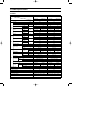
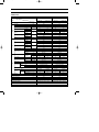
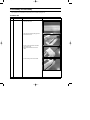
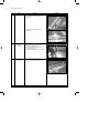
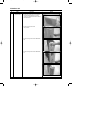
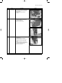
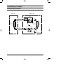
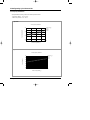
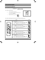
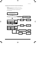
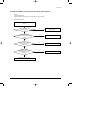
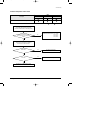
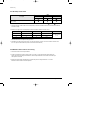
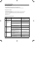
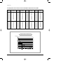
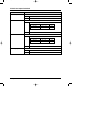
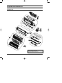
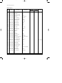
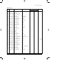
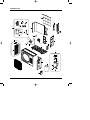
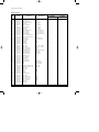
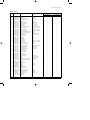
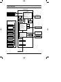
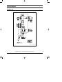
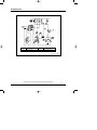
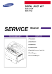
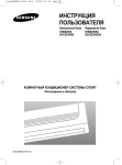
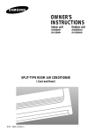
DB98_15924A(3)_co
4/6/04 3:16 PM
Page 3
ROOM AIR CONDITIONER
INDOOR UNIT
OUTDOOR UNIT
SH09AWH
SH09ZWH
AQ09WHWE
KFR-25G/SWA
SH12AWH
SH12ZWH
AQ12WHWE
KFR-35G/SWA
SH09AWHX
SH09ZWHX
UQ09WHWE
KFR-25W/SWA
SH12AWHX
SH12ZWHX
UQ12WHWE
KFR-35W/SWA
SERVICE
AIR CONDITIONER
Manual
CONTENTS
1. Product Specifications
2. Disassembly and Reassembly
3. Refrigerating Cycle Diagram
4. Set Up the Model Option
5. Troubleshooting
6. Exploded Views and Parts List
7. Block Diagram
8. Wiring Diagram
9. Schematic Diagram
DB98_15924A(3)_1
4/6/04 2:59 PM
Page 1
1. Product Specifications
1-1 Table
Model
Item
SH09AWH
Indoor unit
Type
Outdoor unit
Indoor unit
Outdoor unit
Wall-mounted
Wall-mounted
kW
2.75
3.5
Heating
kW
2.90
4.2
Dehumidifying
|/h
1.0
1.4
Cooling
Cooling
Air Volume
Heating
Performance
Cooling
Noise
Heating
Energy Efficiency Ratio
Cooling
Heating
Power
m3/min
dB
Operating Current
25
8.3
8.0
25
9.0
25
38 / 36 / 34
51 / 51
41 / 39 / 37
53 / 53
51 / 51
41 / 39 / 37
38 / 36 / 34
Cooling
Cooling
3.23
1-220 / 240-50
980
1,240
900
1,300
4.5
5.7
%
Heating
Starting Current
Length
Power Cord
3.22
A
Heating
Outer Dimension
Width x Height
x Depth
Weight(Net)
Refrigerant Pipe
95.5
98.0
21.0
30.0
m
-
-
-
-
A
250V-10A
250V-10A
mm
825 x 285 x 189
720 x 548 x 265
825 x 285 x 189
720 x 548 x 265
inch
32.5 x 11.2 x 7.44
28.4 x 21.6 x 10.4
32.5 x 11.2 x 7.44
28.4 x 21.6 x 10.4
kg
8.2
31.3
8.4
33.8
mm x L(m)
ø6.35 x 7.5
ø6.35 x 7.5
GAS
mm x L(m)
ø9.52 x 7.5
ø9.52 x 7.5
D x L(mm)
ø18 x 550
ø18 x 550
Rotary
Rotary
Induction Motor(PSC)
Induction Motor(PSC)
Type
Motor
Type
Rated Output
Oil Type
Type
Blower
Motor
5.7
98.3
Liquid
Drain Hose
Compressor
4.5
96.5
A
Number of Core Wire
Capacity
53 / 53
2.82
1-220 / 240-50
W
Heating
25
2.81
W/W
Cooling
Power Factor
Size
7.3
V-Hz
Power Consumption
Power
SH12AWH
Type
Rated Output
W
Heat Exchanger
Refrigerant Control Unit
900
1,075
DAPHNE FV68S(PVE)
DAPHNE FV68S(PVE)
Cross-flow
Propeller
Cross-flow
Propeller
steel
steel
steel
steel
15
50
15
50
2ROW 14STEP
1ROW 24STEP
2ROW 14STEP
2ROW 24STEP
CAPILLARY TUBE
CAPILLARY TUBE
Freezer Oil Capacity
cc
350
520
Refrigerant to Change(R410A)
g
650
1,020
Protection Device(OLP)
MRA99134-9201
Cooling Test Condition
INDOOR UNIT : DB27˚C WB19˚C
OUTDOOR UNIT : DB35˚C WB24˚C
Maximum Operation Condition
INDOOR UNIT : DB32˚C WB23˚C
OUTDOOR UNIT : DB43˚C WB26˚C
Samsung Electronics
MRA99908-9201
1
DB98_15924A(3)_1
4/6/04 2:59 PM
Page 2
Table(cont.)
Model
Item
SH09ZWH
Indoor unit
Type
Outdoor unit
Outdoor unit
Wall-mounted
kW
2.70
3.5
Heating
kW
2.90
4.0
Dehumidifying
|/h
1.0
1.4
Cooling
Air Volume
Heating
Performance
Cooling
Noise
Heating
Energy Efficiency Ratio
Cooling
Heating
Power
m3/min
dB
Operating Current
25
8.3
8.0
25
9.0
25
38 / 36 / 34
51 / 51
41 / 39 / 37
53 / 53
51 / 51
41 / 39 / 37
38 / 36 / 34
Cooling
Cooling
3.48
1-220 / 240-50
1,000
1,170
900
1,150
4.5
5.2
%
Heating
Starting Current
Length
Power Cord
3.22
A
Heating
Outer Dimension
Width x Height
x Depth
Weight(Net)
Refrigerant Pipe
99.1
96.2
21.0
30.0
m
-
-
-
-
A
250V-10A
250V-10A
mm
825 x 285 x 189
720 x 548 x 265
825 x 285 x 189
720 x 548 x 265
inch
32.5 x 11.2 x 7.44
28.4 x 21.6 x 10.4
32.5 x 11.2 x 7.44
28.4 x 21.6 x 10.4
kg
8.2
31.3
8.4
33.8
mm x L(m)
ø6.35 x 5.0
ø6.35 x 5.0
GAS
mm x L(m)
ø9.52 x 5.0
ø12.70 x 5.0
D x L(mm)
ø18 x 550
ø18 x 550
Rotary
Rotary
Induction Motor(PSC)
Induction Motor(PSC)
Type
Motor
Type
Rated Output
Oil Type
Type
Blower
Motor
5.2
96.9
Liquid
Drain Hose
Compressor
4.0
98.2
A
Number of Core Wire
Capacity
53 / 53
2.99
1-220 / 240-50
W
Heating
25
2.70
W/W
Cooling
Power Factor
Size
7.3
V-Hz
Power Consumption
Type
Rated Output
W
Heat Exchanger
Refrigerant Control Unit
2
Indoor unit
Wall-mounted
Cooling
Power
SH12ZWH
1,005
1,206
SUNISO-4GSD
SUNISO-4GSD
Cross-flow
Propeller
Cross-flow
Propeller
steel
steel
steel
steel
15
50
15
50
2ROW 14STEP
1ROW 24STEP
2ROW 14STEP
2ROW 24STEP
CAPILLARY TUBE
CAPILLARY TUBE
Freezer Oil Capacity
cc
360
600
Refrigerant to Change(R22)
g
580
980
Protection Device(OLP)
RAC12110-9622
Cooling Test Condition
INDOOR UNIT : DB27˚C WB19˚C
OUTDOOR UNIT : DB35˚C WB24˚C
Maximum Operation Condition
INDOOR UNIT : DB32˚C WB23˚C
OUTDOOR UNIT : DB43˚C WB26˚C
RAC12074-9622
Samsung Electronics
DB98_15924A(3)_1
4/6/04 2:59 PM
Page 3
Model
Item
AQ09WHWE
Indoor unit
Type
Outdoor unit
Indoor unit
Outdoor unit
Wall-mounted
Wall-mounted
kW
2.70
3.5
Heating
kW
2.90
4.0
Dehumidifying
|/h
1.0
1.4
Cooling
Cooling
Air Volume
Heating
Performance
Cooling
Noise
Heating
Energy Efficiency Ratio
Cooling
Heating
Power
m3/min
dB
Operating Current
25
8.3
8.0
25
9.0
25
38 / 36 / 34
51 / 51
41 / 39 / 37
53 / 53
51 / 51
41 / 39 / 37
38 / 36 / 34
Cooling
Cooling
3.48
1-220 / 240-50
1,000
1,170
900
1,150
4.5
5.2
%
Heating
Starting Current
Length
Power Cord
3.22
A
Heating
Outer Dimension
Width x Height
x Depth
Weight(Net)
Refrigerant Pipe
99.1
96.2
21.0
30.0
m
-
-
-
-
A
250V-10A
250V-10A
mm
825 x 285 x 189
720 x 548 x 265
825 x 285 x 189
720 x 548 x 265
inch
32.5 x 11.2 x 7.44
28.4 x 21.6 x 10.4
32.5 x 11.2 x 7.44
28.4 x 21.6 x 10.4
kg
8.2
33.0
8.4
33.8
mm x L(m)
ø6.35 x 5.0
ø6.35 x 5.0
GAS
mm x L(m)
ø9.52 x 5.0
ø12.70 x 5.0
D x L(mm)
ø18 x 550
ø18 x 550
Rotary
Rotary
Induction Motor(PSC)
Induction Motor(PSC)
Type
Motor
Type
Rated Output
Oil Type
Type
Blower
Motor
5.2
96.9
Liquid
Drain Hose
Compressor
4.0
98.2
A
Number of Core Wire
Capacity
53 / 53
2.99
1-220 / 240-50
W
Heating
25
2.70
W/W
Cooling
Power Factor
Size
7.3
V-Hz
Power Consumption
Power
AQ12WHWE
Type
Rated Output
W
Heat Exchanger
Refrigerant Control Unit
1,005
1,206
SUNISO-4GSD
SUNISO-4GSD
Cross-flow
Propeller
Cross-flow
Propeller
steel
steel
steel
steel
15
50
15
50
2ROW 14STEP
1ROW 24STEP
2ROW 14STEP
2ROW 24STEP
CAPILLARY TUBE
CAPILLARY TUBE
Freezer Oil Capacity
cc
360
600
Refrigerant to Change(R22)
g
580
980
Protection Device(OLP)
RAC12110-9622
Cooling Test Condition
INDOOR UNIT : DB27˚C WB19˚C
OUTDOOR UNIT : DB35˚C WB24˚C
Maximum Operation Condition
INDOOR UNIT : DB32˚C WB23˚C
OUTDOOR UNIT : DB43˚C WB26˚C
Samsung Electronics
RAC12074-9622
3
DB98_15924A(3)_1
4/6/04 2:59 PM
Page 4
Table(cont.)
Model
Item
KFR-25G / SWA
Indoor unit
Type
Outdoor unit
Outdoor unit
Wall-mounted
kW
2.65
3.5
Heating
kW
2.90
4.0
Dehumidifying
|/h
1.0
1.4
Cooling
Air Volume
Heating
Performance
Cooling
Noise
Heating
Energy Efficiency Ratio
Cooling
Heating
Power
m3/min
dB
Operating Current
Cooling
8.3
25
9.0
25
38 / 36 / 34
51 / 51
41 / 39 / 37
53 / 53
51 / 51
41 / 39 / 37
38 / 36 / 34
Cooling
Length
Power Cord
3.22
3.48
1-220-50
1,000
1,170
900
1,150
4.6
5.8
4.1
5.8
97
92
%
Heating
97
92
A
21.0
30.0
m
-
-
-
-
A
250V-10A
250V-16A
Number of Core Wire
Capacity
Outer Dimension
Width x Height
x Depth
Weight(Net)
Refrigerant Pipe
mm
825 x 285 x 189
720 x 548 x 265
825 x 285 x 189
720 x 548 x 265
inch
32.5 x 11.2 x 7.44
28.4 x 21.6 x 10.4
32.5 x 11.2 x 7.44
28.4 x 21.6 x 10.4
kg
8.2
31.3
8.4
33.8
Liquid
mm x L(m)
ø6.35 x 4.0
ø6.35 x 4.0
GAS
mm x L(m)
ø9.52 x 4.0
ø12.70 x 4.0
Drain Hose
D x L(mm)
Type
Motor
Type
ø18 x 550
ø18 x 550
Rotary(SAMSUNG)
Rotary(SAMSUNG)
Induction Motor(PSC)
Induction Motor(PSC)
Rated Output
Oil Type
Type
Blower
Motor
53 / 53
2.99
1-220-50
A
Heating
25
2.65
W
Heating
Starting Current
Compressor
25
8.0
W/W
Cooling
Power Factor
Size
7.3
V-Hz
Power Consumption
Type
Rated Output
W
Heat Exchanger
Refrigerant Control Unit
4
Indoor unit
Wall-mounted
Cooling
Power
KFR-35G / SWA
990
1,210
SUNISO-4GSD/NOC
SUNISO-4GSD/NOC
Cross-flow
Propeller
Cross-flow
Propeller
steel
steel
steel
steel
15
50
15
50
2ROW 14STEP
1ROW 24STEP
2ROW 14STEP
2ROW 24STEP
CAPILLARY TUBE
CAPILLARY TUBE
Freezer Oil Capacity
cc
360
600
Refrigerant to Change(R22)
g
600
950
Protection Device(OLP)
RAC12054-9622
Cooling Test Condition
INDOOR UNIT : DB27˚C WB19˚C
OUTDOOR UNIT : DB35˚C WB24˚C
Maximum Operation Condition
INDOOR UNIT : DB32˚C WB27.5˚C
OUTDOOR UNIT : DB43˚C WB33˚C
RAC12074-9622
Samsung Electronics
DB98_15924A(3)_1
4/6/04 2:59 PM
Page 5
2. Disassembly and Reassembly
Stop operation of the air conditioner and remove the power cord before repairing the unit.
2-1 Indoor Unit
No
Parts
1
Front Grille
Procedure
Remark
1) Stop the air conditioner operation and
block the main power.
2) Open the Front Grille by pulling right and
left sides of the hook.
3) Loosen 1 of the right screw and detach
the Terminal Cover.
4) Detach the thermistor from the Front
Grille.
5) Loosen 2 fixing screws of Front Grille.
Samsung Electronics
5
DB98_15924A(3)_1
4/6/04 2:59 PM
Page 6
Disassembly and Reassembly
No
Parts
Procedure
Remark
6) Unlock 2 hooks to fix Panel Front and
Tray Drain.
7) Unlock 3 hooks to fix Panel Front and
Back-Body.
6
2
Control-In
(Main PCB)
1) Take all the connector of PCB upper side
out. (Inclusion Power Cord)
2) Detach the outdoor unit connection wire
from the Terminal Block.
3) Loosen 4 fixing screws of Ass'y Control-In.
3
Tray Drain
1) Pull Tray Drain out from the Back Body.
Samsung Electronics
DB98_15924A(3)_1
4/6/04 2:59 PM
Page 7
Disassembly and Reassembly
No
Parts
4
Heat Exchanger
5
Fan Motor
&
Cross Fan
Samsung Electronics
Procedure
Remark
1)
2)
3)
4)
Loosen 2 fixing earth screws of right side.
Detach the Connection Pipe.
Detach the Holder Pipe at the rear side.
Loosen the 3 fixing screws of right and left
side.
5) Lifting the Heat Exchanger up a little to
push the up side for separation from the
indoor unit.
1) Loosen the fixing screw and detach the
Motor Holder.
2) Detach the Fan Motor from the Fan.
3) Detach the Fan From the left Holder
Bearing.
7
DB98_15924A(3)_1
4/6/04 2:59 PM
Page 8
2-2 Outdoor Unit
No
Parts
1
Common Work
Procedure
Remark
1) Loosen each 3 fixing screws on both right
and left Cabinet-Side edge and a fixing
screw on the Cabinet-Front lower to detach
the Cabinet-Front.
2) Loosen 2 fixing screws of the
Ass'y-Control.
3) Loosen 6 fixing screws of the Cabinet-Side
RH.
4) Loosen 2 fixing screws of the Cabinet-Side
LF.
8
Samsung Electronics
DB98_15924A(3)_1
4/6/04 2:59 PM
Page 9
Disassembly and Reassembly
No
Parts
2
Fan & Motor
3
Heat Exchanger
4
Compressor
Samsung Electronics
Procedure
Remark
1) Detach the Nut Flange.(Turn counterclockwise because the screw is right-handed)
2) Detach the Fan.
3) Loosen 4 fixing screws to detach
the Motor.
1) Loosen 2 fixing screws on both sides.
2) Disassemble the pipe in both inlet and
outlet with welding torch.
3) Detach the Heat Exchanger.
1) Loosen the Terminal Cover nut to open the
Terminal Cover.
2) Disassemble the cloth sound felt.
3) Disassemble the pipe in both inlet and
outlet of the Compressor with welding
torch.
4) Disassemble the pipe in both inlet and
outlet of the Condenser with welding torch.
5) Loosen the 3 bolts at the bottom.
6) Detach the Compressor.
9
DB98_15924A(3)_1
4/6/04 2:59 PM
Page 10
3. Refrigerating Cycle Diagram
3-1 Refrigerating Cycle Diagram
Outdoor Unit
Indoor Unit
✳Note
Capillary tube
T1
2-Way valve
Check valve
Liquid side
Heat
Exchanger
(Evaporator)
Cross fan
Heat
Exchanger
(Evaporator)
Propeller fan
Capillary tube
T2
Gas side
3-Way valve
4-Way valve
Cooling
Compressor
Heating
Gas Leak Check Polnt
10
Samsung Electronics
DB98_15924A(3)_1
4/6/04 2:59 PM
Page 11
3-2 Refrigerating Cycle Characteristic
3-2-1 Capacity Distributions
Capacity Distributions according to indoor and outdoor temperature variation.
- Indoor Temp. Variation : 15.0˚C ~ 25.0˚C
- Outdoor Temp. Variation : 1.0˚C ~ 20.0˚C
■ 9,000BTU
Heating Capacity Distribution
Heating Capacity(kW)
4.00
Indoor Temp.( C)
DB15.0
DB20.0
DB25.0
3.00
2.00
1.00
1.0/0.0
7.0/6.0
20.0/15.0
Outdoor Temp.(DB/WB C)
■ 12,000BTU
Heating Capacity
Heating Capacity Distribution
6.00
Indoor Temp.( C)
5.00
DB15.0
DB20.0
DB25.0
4.00
3.00
2.00
1.00
0.00
1.0/0.0
7.0/6.0
20.0/15.0
Outdoor Temp.(DB/WB C)
Samsung Electronics
11
DB98_15924A(3)_1
4/6/04 2:59 PM
Page 12
Refrigerating Cycle Diagram
3-2-2 Power Consumption Distributions
Power consumption distributions according to indoor and outdoor temperature variation.
- Indoor Temp. Variation : 15.0˚C ~ 25.0˚C
- Outdoor Temp. Variation : 1.0˚C ~ 20.0˚C
■ 9,000BTU
Power consumption Distribution(Heating mode)
Indoor Temp.( C)
1,100
Power consumption(W)
DB25.0
1,000
DB20.0
DB15.0
900
800
700
1.0/0.0
7.0/6.0
20.0/15.0
Outdoor Temp.(DB/WB C)
■ 12,000BTU
Power consumption Distribution(Heating mode)
Indoor Temp.( C)
DB25.0
Power consumption(W)
1,600
1,500
DB20.0
1,400
DB15.0
1,300
1,200
1,100
1,000
25
35
45
Outdoor Temp.(DB/WB C)
12
Samsung Electronics
DB98_15924A(3)_1
4/6/04 2:59 PM
Page 13
Refrigerating Cycle Diagram
3-2-3 Capacity and Power Consumption Distributions
Capacity and power consumption distributions according to the length of connecting pipe between indoor unit and
outdoor unit.
■ 9,000BTU
Power consumption(Heating)
Heating Capacity
1,100
Power consumption(W)
Heating Capacity(kW)
4.00
3.00
2.00
1.00
7.5
1,000
900
800
700
7.5
15.0
Length of Connecting Pipe(m)
15.0
Length of Connecting Pipe(m)
■ 12,000BTU
Power consumption(Heating)
Heating Capacity
1,350
Power consumption(W)
Heating Capacity(kW)
4.20
4.10
4.00
3.90
3.80
7.5
15.0
Length of Connecting Pipe(m)
Samsung Electronics
1,300
1,250
1,200
1,150
7.5
15.0
Length of Connecting Pipe(m)
13
DB98_15924A(3)_1
4/6/04 2:59 PM
Page 14
4. Set Up the Model Option
4-1 Setting Option Setup Method
ex) Option No. :
Step 1 : Enter the Option Setup mode.
1st
Take out the batteries of remote control.
2nd
Press the temperature
insert the battery again.
3rd
Make sure the remocon display shown as
button simultaneously and
.
Step 2 : Enter the Option Setup mode and select your option according to the following procedure.
Feature
1
Display
Setting Option SEG1.
Push the
button to set the display panel to
.
Every time you push the button, the display panel reads
...
repeatedly.
2
Setting Option SEG2.
Push the
button to set the display panel to
.
Every time you push the button, the display panel reads
...
repeatedly.
3
3
1,4
Change it into the set display of Option SEG3 and SEG4
with the
2,5
4
button.
Setting Option SEG3.
Push the
button to set the display panel to
.
Every time you push the button, the display panel reads
...
repeatedly.
5
Setting Option SEG4.
Push the
button to set the display panel to
.
Every time you push the button, the display panel reads
...
repeatedly.
14
Samsung Electronics
DB98_15924A(3)_1
4/6/04 3:00 PM
Page 15
Set Up the Model Option
Feature
Display
6
Change it into the set display of Option SEG5 and SEG6
with the
button.
7
Setting Option SEG5.
Push the
button to set the display panel to
.
Every time you push the button, the display panel reads
...
repeatedly.
8
Setting Option SEG6.
Push the
button to set the display panel to
.
Every time you push the button, the display panel reads
...
repeatedly.
6,9
7,10
8,11
9
Change it into the set display of Option SEG7 and SEG8
with the
button.
10
Setting Option SEG7.
Push the
button to set the display panel to
.
Every time you push the button, the display panel reads
...
repeatedly.
11
Setting Option SEG8.
Push the
button to set the display panel to
.
Every time you push the button, the display panel reads
...
repeatedly.
12
Change it into the set display of Option SEG9 and SEG10
with the
12
13
14
button.
13
Setting Option SEG9.
Push the
button to set the display panel to
.
Every time you push the button, the display panel reads
...
repeatedly.
14
Setting Option SEG10.
Push the
button to set the display panel to
.
Every time you push the button, the display panel reads
...
repeatedly.
Samsung Electronics
15
DB98_15924A(3)_1
4/6/04 3:00 PM
Page 16
Set Up the Model Option
Step 3 : Upon completion of the selection, check you made right selections.
Whenever you press the
button, the set Option will be displayed.
Step 4 : Pressing the ON/OFF button (
)
When pressing the operation ON/OFF key with the direction of remote controller for unit, the sound "Ding" is heard and the
OPERATION LED lamp is flickering at the same time, then the input of option is completed. (If the "ding" sound isn't heard,
try again pressing the ON/OFF button.)
Step 5 : Unit operation test-run
First, Remove the battery from the remote controller.
Second, Re-insert the battery into the remote controller.
Third, Press ON/OFF (
) key with the direction of remote controller for set.
• Error Mode
16
1st
If all lamps of indoor unit are flickering, Plug out, plug in power plug again and press ON/OFF key to retry.
2nd
If the unit is not working properly or all lamps are continuously flickering after setting the option code, see if the
correct option code is set up for its model.
Samsung Electronics
DB98_15924A(3)_1
4/6/04 3:00 PM
Page 17
4-2 Table of the option Code
Option Code
Model
SEG1
SEG2
SEG3
SEG4
SEG5
SEG6
SEG7
SEG8
SEG9
SEG10
2
5
0
2
5
7
0
3
4
0
2
5
0
2
5
7
0
0
c
8
2
5
0
2
5
7
0
0
F
b
SH12AWH
SH12ZWH
AQ12WHWE
KFR-35G / SWA
SH09AWH
SH09ZWH
AQ09WHWE
KFR-25G / SWA
Samsung Electronics
17
DB98_15924A(3)_1
4/6/04 3:00 PM
Page 18
5. Troubleshooting
Check the basic items first to judge if the problem was caused by breakdown or misuse. If none of the basic items are related to the
problem, please scrutinize the machine according to the 'Breakdown Diagnosis by Symptoms' method.
5-1 Basic Breakdown Diagnosis Items
1.
The input voltage should be rating voltage ±10% range.
The airconditioner may not operate properly if the voltage is out of this range.
2.
Is the link cable linking the indoor unit and the outdoor unit linked properly?
The indoor unit and the outdoor unit shall be linked by 5 cables.
Check the terminals if the indoor unit and outdoor unit are properly linked by the same number of cables.
Otherwise the airconditioner may not operate properly.
3.
When a problem occurs due to the contents illustrated in the table below it is a symptom not related to the malfunction of the
airconditioner.
No
18
Operation of air conditioner
Explanation
1
The OPERATION indication LED(GREEN) blinks when a
power plug of the indoor unit is plugged in for the first time.
It indicates power is on. The LED stops blinking if the operation ON/OFF button on the remote control unit is pushed.
2
In a COOL operation mode, the compressor does not
operate at a room temperature higher than the setting
temperature that the INDOOR FAN should operate.
In a HEAT operation mode, the compressor does not operate
at a room temperature lower than the setting temperature
that indoor fan should operate.
In happens after a delay of 3 minutes when the compressor
is reoperated. The same phenomenon occurs when a power
is on.
As a phenomenon that the compressor is reoperated after a
delay of 3 minutes, the indoor fan is adjusted automatically
with reference to a temperature of the air blew.
3
Fan speed setting is not allowed in DRY(
The speed of the indoor fan is set to LL in DRY mode.
Fan speed is selected automatically in AUTO mode.
4
Compressor stops operation intermittently in DRY(
mode.
5
Compressor of the outdoor unit is operating although it is
turned off in a HEAT mode.
When the unit is turned off while de-ice is activated,
the compressor continues operation for up to 9 minutes
(maximum) until the deice is completed.
6
Timer LED(GREEN) of the indoor unit lights up and the
air conditioner does not operate.
Timer is being activated and the unit is in ready mode.
The unit operates normally if the timer operation is cancelled.
7
The compressor and indoor fan stop intermittently in
HEAT mode.
The compressor and indoor fan stop intermittently if room
temperature exceeds a setting temperature in order to protect
the compressor from overheated air in a HEAT mode.
8
Indoor fan and outdoor fan stop operation intermittently
in a HEAT mode.
The compressor operates in a reverse cycle to remove
exterior ice in a HEAT mode, and indoor fan and outdoor fan
do not operate intermittently for within 20% of the total heater
operation
9
The compressor stops intermittently in a COOL mode or
DRY mode, and fan speed of the indoor unit decreases.
The compressor stops intermittently or the fan speed of the
indoor unit decreases to prevent inside/outside air frozen
depending on the inside/outside air temperature.
) mode.
)
Compressor operation is controlled automatically in DRY
mode depending on the room temperature and humidity.
Samsung Electronics
DB98_15924A(3)_1
4/6/04 3:00 PM
Page 19
5-2 Trouble check in the initial status
5-2-1 Diagnosis and marking of the part in trouble.
Please check the air conditioner operation status and write the check result in the chart in the room.
LAMP
OPERATION
Description
TIMER
TURBO
Indoor unit room temperature sensor error
(open or short)
Indoor unit heat exchanger temperature sensor error
(open or short)
Indoor fan motor mal function
EEPROM error
Option error
(option wasn't set up or option data error)
: Lamp off
: Lamp flickering
5-2-2 Operation with abnormal motion
No
1
2
Abnormal condition
No response from
the remote control
operation signal.
Unable to operate the
outdoor unit
Samsung Electronics
Inspection
• Plug out and plug in 5 seconds later.
• Press the TURBO button with the
remote control.
• In 3 minutes, check the voltage
between the indoor unit terminal
block N(1) and 1.
Initial Diagnosis
Able to operate the
remote control.
OK
Unable to operate
the remote control.
Press the
button in the indoor unit.
• If it operates, the remote control and
indoor unit receiver are in trouble.
• If not, the indoor unit is in trouble.
AC200V ~ AC240V
Problem with the outdoor unit or PCB
No power source
displayed.
Problem with the relay (RY71) or PCB
19
DB98_15924A(3)_1
4/6/04 3:00 PM
Page 20
5-3 Breakdown diagnosis by symptoms
5-3-1 No Power (completely dead)-Initial diagnosis
1. Checklist :
1) Is input voltage normal?
2) Is AC power linked correctly?
3) Is input voltage of DC regulator IC KA7805 (IC02) normal? (11VDC-12.5VDC)
4) Is output voltage of DC regulator IC KA7805 (IC02) normal? (4.5VDC-5.5VDC)
2. Troubleshooting procedure
Unplug the power cord and plug it after 5 seconds
Press the Power Button on
the remote control unit to operate the air
conditioner
operate
◆ Check the display board
does not operate
◆ Check the indoor unit control board
Check whether two wires
of power cord are connected correctly to the
terminal block and control board.
No
Reconnect wires correctly
Yes
Check whether the fuse on the
control board is normal.
F701: 3.15[A]/250[V]
No
Replace fuse
Yes
Check the output of
SMPS on the control board.
Input power: AC230±15%[V]
IC02 Input: DC 12[V]
IC02 output: DC 5[V]
No
Replace the control board
Yes
◆ Check the setting temperature
20
Samsung Electronics
DB98_15924A(3)_1
4/6/04 3:00 PM
Page 21
Troubleshooting
5-3-2 When the Indoor Unit Fan Does Not Operate. (Initial Diagnosis)
1. Checklist :
1) Is the indoor unit fan motor properly connected with the connector (CN72)?
2) Is the AC voltage correct?
3) Is HALL IC in indoor fan motor properly connected with the connector (CN44)?
4) Is the running capacitor (CR71) properly connected with PCB board?
2. Troubleshooting procedure
After unplugging out the power cord should
be reconnected within 5 seconds.
Yes
No
Check as in the procedure
"NO power parts"
Does the OPERATION lamp blink?
Yes
No
Micom is
out of order.
Micom
should be replaced
No
PCB is
out of order.
PCB should be
replaced.
Does the Solid State Relay(SS71) work properly?
Test rod location
+
-
SS71-
SS71-
Normal
Voltage
12V
Yes
Is the supply voltage of the fan motor sufficient?
Test rod location
PCB CN72
Condition
pin #3 and #5
Fan operate
Normal
Voltage
About AC
180V
Motor Fan-Capacitor is out of order
Replace Motor
Fan-Capacitor
Yes
Fan motor
is out of order.
Samsung Electronics
Fan motor
should be replaced.
21
DB98_15924A(3)_1
4/6/04 3:00 PM
Page 22
Troubleshooting
5-3-3 When the Outdoor Unit Does Not Operate. (Initial Diagnosis)
1. Checklist :
1) Is input voltage normal?
2) Is the set temperature of the remote control higher than room temperature in COOL mode?
3) Is the set temperature of the remote control lower than room temperature in HEAT mode?
4) Is the POWER IN connector (CN71) linked correctly?
5) Is the outdoor unit properly connected with the TERMINAL BLOCK connector(N(1), 1, 2, 3)?
2. Troubleshooting procedure
After unplugging out the power cord should be
reconnected within 5 seconds.
No
Check as in the procedure
"No Power parts"
Does the OPERATION lamp blink
Yes
Room temperature sensor is
out of order
Yes
Does the timer lamp blink during operation?
!
No
@
#
No
Is the power relay RY71 operated by adjusting
the room temperature?
Test rod location
+
-
Condition
IC04 Pin No.38
GND
RY71 ON
PCB should be checked.
Micom is
out of order.
Normal
Voltage
PCB should be checked.
DC 4.8V
Yes
Is rating voltage ±10% range applied relay between
Terminal block No. N(1) and No. 1
No
Power relay is
out of order
Power relay should be
replaced.
Yes
Outdoor unit is out of order.
!
Yes
No
@
Is the room sensor normal register?
10°C
20°C
30°C
17.96kΩ
12.09kΩ
8.3kΩ
#
22
Samsung Electronics
DB98_15924A(3)_1
4/6/04 3:00 PM
Page 23
Troubleshooting
5-3-4 When the UP/DOWN Louver Motor Does Not Operate. (Initial Diagnosis)
1. Checklist :
1) Is input voltage normal?
2) Is the UP/DOWN louver motor properly connected with the connector (CN61)?
2. Troubleshooting procedure
Remove power cord and plug in again in approx.
5 seconds.
No
Is STD lamp blinking?
Check as in the procedure
"No Power parts".
Yes
Does operation start when
swing button of the remote control unit
pushed?
Yes
Normal
No
Voltage at pin #57~#60
of micom (IC04) change?
(Squarewave)
No
Micom (IC04) is faulty.
Yes
Voltage at pin #16 of
IC06(ULN2003A) and #10~#12 of
IC08(ULN2003A) change?
(Squarewave)
No
Driver IC06/08 (ULN2003A) is faulty.
Yes
UP/DOWN louver motor is faulty.
Samsung Electronics
23
DB98_15924A(3)_1
4/6/04 3:00 PM
Page 24
Troubleshooting
5-3-5 In the HEAT mode, When there is no warm air current. Check this fist;
1. Checklist :
1) Is the set temperature of Remote Control lower than room temperature in Heat mode?
2) Is the Indoor PCB properly connected with the CN71 connector?
2. Troubleshooting procedure
After training on, the heating operation
should start in 5 minutes.
No
Is the number #38 of Micom (IC04)
DC 5.0V?
No
Abnormal Micom
Yes
Is the number checking
#11 of IC05 (ULN2003A) LOW?
No
Abnormal Micom
Yes
Is the voltage between
CN71 #1 and CN71 #5 rating voltage
±10% range
No
Abnormal IC05
Yes
Abnormal 4-Way valve of Outdoor Unit.
or connecting Cable
4-Way valve should be replaced
or connecting Cable Check.
24
No
Abnormal RY73
PCB should be replaced.
Samsung Electronics
DB98_15924A(3)_1
4/6/04 3:00 PM
Page 25
Troubleshooting
5-3-6 Room temperature sensor failure
LAMP
OPERATION
Description
TIMER
TURBO
Indoor unit room temperature sensor error(open or short)
: Lamp off
: Lamp flickering
Detach the assembly sensor from the
ASS'Y PCB CN43 connector and measure
the sensor resistance with an ohmmeter (tester).
Is the sensor resistance value
10KΩ ±3% at the room temperature
of 25˚C?
No
ASS'Y Sensor Replace
SENSOR Resistance Value : 20˚C-12.09kΩ
SENSOR Resistance Value : 30˚C-8.31kΩ
SENSOR Resistance Value : 35˚C-6.94kΩ
SENSOR Resistance Value : 40˚C-5.83kΩ
Yes
Connect the sensor to CN43,
supply power, and measure the voltage of
#1 and #2 of the CN43 connector.
Yes
Poor ASS'Y PCB Replace
Below 0.5V?
No
Yes
Over 4.9V?
Poor ASS'Y PCB Replace
No
MICOM Error or Connector(CN43) check
Samsung Electronics
25
DB98_15924A(3)_1
4/6/04 3:00 PM
Page 26
Troubleshooting
5-3-7 Room Pipe sensor failure
LAMP
OPERATION
Description
TIMER
TURBO
Indoor unit heat exchanger temperature sensor error
(open or short)
: Lamp off
: Lamp flickering
1. Check the assembly condition of the sensor connector(CN43) on the indoor unit Main PCB and if not assembled, reassemble the
connector accurately.
2. Detach the room pipe sensor connector(CN43) and check the resistance between connector 3 and 4.
Temperature(˚C)
Resistance Value(Kohm)
Temperature(˚C)
Resistance Value(Kohm)
15
14.68
30
8.31
20
12.09
35
6.94
25
10
40
5.83
Others
The data tolerance
is ±3%.
If the above data is not met, replace the room pipe sensor.
3. Assemble the room pipe sensor to PCB, plug in, and check the voltage of connector 3 and 4. If the resistance is below 0.5V or
over 4.9V, replace the indoor Main PCB. (short or disconnected in the PCB board)
5-3-8 When the remote control is not receiving.
1. Check if the connector was normally assembled.
2. Put the set in operation and check the voltage of No. 3(+) and No. 2(-) of the main PCB CN91 while operating the
remote control. When the voltage descends below 3V, the assembly module PCB is normal and the main PCB is poor.
Then replace the main PCB.
3. Replace the assembly display PCB because the module PCB is poor if the voltage between No. 2~3 of CN91
maintains 5V after the remote control starts operation.
26
Samsung Electronics
DB98_15924A(3)_1
4/6/04 3:00 PM
Page 27
5-4 PCB Inspection Method
5-4-1 Pre-inspection Notices
1. Check if you pulled out the AC power plug when you eliminate the PCB or front panel.
2. Don't hold the PCB side not impose excessive force on it to eliminate the PCB.
3. Don't pull the lead wire but hold the whole housing to connect or disconnect a connector to the PCB.
5-4-2 Inspection Procedure
1. Check connector connection and peeling of PCB or bronze coating pattern when you think the PCB is broken.
2. The PCB is composed of the 3 parts.
● Main PCB Part : MICOM and surrounding circuit, relay, room fan motor driving circuit and control circuit,
sensor driving circuit, power circuit of DC12V and DC5V, and buzzer driving circuit.
● Display part : LED lamp
● Switch part : Switch
5-4-3 Detailed Inspection Procedure
No
Procedure
1
Plug out and pull the PCB
out of the electronic box.
Check the PCB fuse.
1) Is the fuse disconnected? (F701)
2
Supply power.
If the operating lamp
twinkles at this time,
the above 1)~3) have
no relation.
Checking the power voltage.
3
4
Press the ON/OFF button
and operate TURBO
mode.
But, exclude the
RESERVE operation.
Inspection Method
• Overcurrent
• Indoor Fan Motor Short
• AC Part Pattern Short of the MAIN PCB
1) Is the DB71input voltage AC200V~AC240V?
• Power Cord is fault, Fuse open. Wrong
Power Cable Wiring, AC Part is faulty.
2) Is the voltage between both terminals of the
C102 on the 2nd side of the transformer AC12V
±0.5V?
• Switching Trans or Power Circuit is faulty
3) Is the voltage between both terminals of OUT
and GND of IC02(KA78L05) DC5V ±0.5V?
• Power Circuit is faulty, Load Short
Checking the power voltage.
1) Check the voltage of the relay(RY71) coil(IC05 PIN
#11 and GND : 0V, PIN#6 and GND : 5V) during
operation(3 minutes after TURBO operation).
• Relay(RY71) Coil Disconnection, IC05 is
faulty
2) Check the voltage of both terminals of
terminal block 1 and N(1) after 3 minute
operation.: AC220V
• Relay(RY71) Contact is faulty
Press the ON/OFF button. 1) Is the voltage over AC180V being imposed
on terminal #3 and #5 of the fan motor
1. FAN Speed [High]
connector(CN72)?
2. Continuous Operation
Samsung Electronics
Cause
• Fan Motor of the indoor is faulty
2) The fan motor of the indoor unit doesn't run.
• Fan Motor Connector(CN72) is faulty
3) The power voltage between terminal #3 and #5
of the connector(CN72) is 0V.
• ASS'Y Main PCB is faulty
• Connection is faulty
27
DB98_15924A(3)_1
4/6/04 3:00 PM
Page 28
Troubleshooting
5-4-4 Temperature Sensor Feature Conversion Table(Room Temperature Sensor); 103AT
Temperature Sensor Resistance Temperature Sensor Resistance Temperature Sensor Resistance Temperature Sensor Resistance
[˚C]
[˚C]
[˚C]
[˚C]
[Kohm]
[Kohm]
[Kohm]
[Kohm]
70
69
68
67
66
65
64
63
62
61
60
2.229
2.296
2.365
2.437
2.512
2.589
2.669
2.752
2.838
2.928
3.021
49
48
47
46
45
44
43
42
41
40
4.300
4.444
4.594
4.749
4.912
5.080
5.256
5.439
5.630
5.828
29
28
27
26
25
24
23
22
21
20
8.622
8.944
9.281
9.632
10
10.380
10.780
11.200
11.630
12.090
9
8
7
6
5
4
3
2
1
0
18.700
19.480
20.290
21.150
22.050
22.990
23.900
25.030
26.130
27.280
59
58
57
56
55
54
53
52
51
50
3.116
3.216
3.319
3.426
3.537
3.652
3.772
3.897
4.026
4.161
39
38
37
36
35
34
33
32
31
30
6.033
6.246
6.468
6.699
6.941
7.192
7.455
7.729
8.015
8.313
19
18
17
16
15
14
13
12
11
10
12.560
13.060
13.570
14.120
14.680
15.280
15.900
16.550
17.240
17.960
-1
-2
-3
-4
-5
-6
-7
-8
-9
28.470
29.720
31.040
32.430
33.890
35.430
37.050
38.760
40.560
Temperature Sensor Characteristic Curve
Temperature
(˚C)
70
60
50
40
30
At the temperature of 25˚C(10KΩ)
20
10
0
-10
-9
5
10
15
20
25
30
35
40
Resistance Value (Kohm)
28
Samsung Electronics
DB98_15924A(3)_1
4/6/04 3:00 PM
Page 29
5-5 Main Part Inspection Method
Part
Room Temperature Sensor
Room Fan Motor
Breakdown Inspection Method
Measure resistance with a tester
Normal
At the normal temperature 37kΩ~ 8.3kΩ(-7˚C~+30˚C) *Refer to Table 5-4-4.
Abnormal
∞, 0Ω . . . Open or Short
Measure the resistance between terminals of the connector (CN72) with a tester.
Normal
Abnormal
Outdoor Fan Motor
At the normal temperature (10˚C ~ 30˚C)
Compare terminal
Resistance
Remark
Yellow, Blue
404.4Ω ± 10%
Main
Yellow, Red
340Ω ± 10%
Sub
∞, 0Ω . . . Open or Short
Measure the resistance between motor wires with a tester.
Normal
At the normal temperature (10˚C ~ 30˚C)
Compare terminal
Abnormal
Stepping Motor
Samsung Electronics
Resistance
Remark
Yellow, Red
360Ω ± 10%
Main
Black, Yellow
328Ω ± 10%
Sub
∞, 0Ω . . . Open or Short
Measure the resistance between the red wire and each terminal wire with a tester.
Normal
About 300Ω at the normal temperature (20˚C ~ 30˚C)
Abnormal
∞, 0Ω . . . Open or Short
29
DB98_15924A(3)_1
4/6/04 3:00 PM
Page 30
6. Exploded Views and Parts List
6-1 Indoor Unit
6
7
1
1-2
1-7
1-1
1-8
1-3
1-5
2
1-4
1-6
4
9
2-1
2-3
2-2
5
5-1
3-6
3-8
3-8-1
3-4
5-4
3
3-1
3-7
3-2
5-2
5-3
3-5
3-3
8
You can search for the updated part code
number through the ITSELF.
URL : http://itself.sec.samsung.co.kr
30
Samsung Electronics
DB98_15924A(3)_1
4/6/04 3:00 PM
Page 31
Exploded Views and Parts List
■
Parts List
Q'TY
No.
Code No.
Description
Specification
Remark
SH09AWH
SH12AWH
1
DB94-00454B
ASS'Y-BACK BODY
ASS'Y
1
1
1-1
DB61-01632A
BACK-BODY
HIPS
1
1
1-2
DB69-00834A
CUSHION-BACK BODY
EPS
1
1
1-3
DB61-01634A
SUPPORTER-EVAP RH
HIPS
1
1
1-4
DB31-00219A
MOTOR-IN
YDK-20S4F8C-1
1
1
1-5
DB94-00456A
ASS'Y-CROSS FAN
OD92x635
1
1
1-6
DB97-02075A
ASS'Y BOLT-SPECIAL
ASS'Y
1
1
1-7
DB73-00181A
RUBBER-BEARING
RUBBER
1
1
1-8
DB94-40007A
MOLD-BEARING
BEARING
1
1
2
DB96-03112A
ASS'Y CYCLE IN
ASS'Y
-
1
DB96-03112B
ASS'Y CYCLE IN
ASS'Y
1
-
2-1
DB63-00850A
COVER BEARING
ABS
1
1
2-2
DB60-00118A
SPACE-EVAP-LOW
PVC
1
1
2-3
DB96-04716A
ASS'Y-EVAP TOTAL
1.3S, 2x14
-
1
DB96-04716B
ASS'Y-EVAP TOTAL
1.5S, 2x14
1
-
3
DB94-00457D
ASS'Y-TRAY DRAIN
ASS'Y
1
1
3-1
DB63-00848A
TRAY-DRAIN
ABS
1
1
3-2
DB61-01635A
BLADE-H
HIPS
1
1
3-3
DB61-01636A
BLADE-V
PP
2
2
3-4
DB63-00849A
STABILIZER
ABS
1
1
3-5
DB69-00839A
CUSHION-TRAY RH
EPS30
1
1
3-6
DB73-00180A
RUBBER-CAP
GUM-EPM
1
1
3-7
DB95-20138A
ASS'Y-STEPPING-MOTOR
PM24-600g, 24BYJ48
1
1
3-8
DB94-00458B
ASS'Y DRAIN HOSE
ASS'Y
1
1
3-8-1
DB61-01715A
CLIP TERMINAL HOSE
STS, PI1.0
1
1
4
DB93-02481L
ASS'Y-CONTROL IN
ASS'Y
1
1
5
DB92-00536A
ASS'Y-PANEL FRONT
ASS'Y
1
1
5-1
DB64-00989A
PANEL-FRONT
PS
1
1
5-2
DB64-00990A
GRILLE-AIR INLET
HIPS
1
1
5-3
DB97-02064A
ASS'Y-COVER DISPLAY
ASS'Y
1
1
5-4
DB63-00846A
GUARD-AIR FILTER
PP
2
2
6
DB70-00406A
PLATE-HANGER
SGCC-M T0.6x320x650
1
1
7
DB61-01638A
HOLDER-PIPE
PS
1
1
8
DB63-00844A
COVER TERMINAL
ABS-V0
1
1
9
DB93-02532B
ASS'Y-REMOCON
REMOCON
1
1
Samsung Electronics
Refer to page 40
31
DB98_15924A(3)_1
4/6/04 3:00 PM
Page 32
Exploded Views and Parts List
■
Parts List(cont.)
Q'TY
No.
Code No.
Description
1
DB94-00454B
ASS'Y-BACK BODY
1-1
DB61-01632A
1-2
Specification
SH09ZWH
AQ09WHWE
SH12ZWH
AQ12WHWE
ASS'Y
1
1
BACK-BODY
HIPS
1
1
DB69-00834A
CUSHION-BACK BODY
EPS
1
1
1-3
DB61-01634A
SUPPORTER-EVAP RH
HIPS
1
1
1-4
DB31-00219A
MOTOR-IN
YDK-20S4F8C-1
1
1
1-5
DB94-00456A
ASS'Y-CROSS FAN
OD92x635
1
1
1-6
DB97-02075A
ASS'Y BOLT-SPECIAL
ASS'Y
1
1
1-7
DB73-00181A
RUBBER-BEARING
RUBBER
1
1
1-8
DB94-40007A
MOLD-BEARING
BEARING
1
1
2
DB96-03112C
ASS'Y CYCLE IN
ASS'Y
-
1
DB96-03112D
ASS'Y CYCLE IN
ASS'Y
1
-
2-1
DB63-00850A
COVER BEARING
ABS
1
1
2-2
DB60-00118A
SPACE-EVAP-LOW
PVC
1
1
2-3
DB96-03060A
ASS'Y-EVAP
1.3S, 2x14
-
1
DB96-03257A
ASS'Y-EVAP
1.5S, 2x14
1
-
3
DB94-00457D
ASS'Y-TRAY DRAIN
ASS'Y
1
1
3-1
DB63-00848A
TRAY-DRAIN
ABS
1
1
3-2
DB61-01635A
BLADE-H
HIPS
1
1
3-3
DB61-01636A
BLADE-V
PP
2
2
3-4
DB63-00849A
STABILIZER
ABS
1
1
3-5
DB69-00839A
CUSHION-TRAY RH
EPS30
1
1
3-6
DB73-00180A
RUBBER-CAP
GUM-EPM
1
1
3-7
DB95-20138A
ASS'Y-STEPPING-MOTOR
PM24-600g, 24BYJ48
1
1
3-8
DB94-00458B
ASS'Y DRAIN HOSE
ASS'Y
1
1
3-8-1
DB61-01715A
CLIP TERMINAL HOSE
STS, PI1.0
1
1
4
DB93-02481✳
ASS'Y-CONTROL IN
ASS'Y
1
1
5
DB92-00536A
ASS'Y-PANEL FRONT
ASS'Y
1
1
5-1
DB64-00989A
PANEL-FRONT
PS
1
1
5-2
DB64-00990A
GRILLE-AIR INLET
HIPS
1
1
5-3
DB97-02064A
ASS'Y-COVER DISPLAY
ASS'Y
1
1
5-4
DB63-00846A
GUARD-AIR FILTER
PP
2
2
6
DB70-00406A
PLATE-HANGER
SGCC-M T0.6x320x650
1
1
7
DB61-01638A
HOLDER-PIPE
PS
1
1
8
DB63-00844A
COVER TERMINAL
ABS-V0
1
1
9
DB93-02532B
ASS'Y-REMOCON
REMOCON
1
1
32
Remark
Refer to page 40
Samsung Electronics
DB98_15924A(3)_1
4/6/04 3:00 PM
Page 33
Exploded Views and Parts List
■
Parts List(cont.)
Q'TY
No.
Code No.
1
DB94-00454B
ASS'Y-BACK BODY
ASS'Y
1
1
1-1
DB61-01632A
BACK-BODY
HIPS
1
1
1-2
DB69-00834A
CUSHION-BACK BODY
EPS
1
1
1-3
DB61-01634A
SUPPORTER-EVAP RH
HIPS
1
1
1-4
DB31-00219A
MOTOR-IN
YDK-20S4F8C-1
1
1
1-5
DB94-00456A
ASS'Y-CROSS FAN
OD92x635
1
1
1-6
DB97-02075A
ASS'Y BOLT-SPECIAL
ASS'Y
1
1
1-7
DB73-00181A
RUBBER-BEARING
RUBBER
1
1
1-8
DB94-40007A
MOLD-BEARING
BEARING
1
1
2
DB96-03112C
ASS'Y CYCLE IN
ASS'Y
-
1
DB96-03112D
ASS'Y CYCLE IN
ASS'Y
1
-
2-1
DB63-00850A
COVER BEARING
ABS
1
1
2-2
DB60-00118A
SPACE-EVAP-LOW
PVC
1
1
2-3
DB96-03060A
ASS'Y-EVAP
1.3S, 2x14
-
1
DB96-03257A
ASS'Y-EVAP
1.5S, 2x14
1
-
3
DB94-00457D
ASS'Y-TRAY DRAIN
ASS'Y
1
1
3-1
DB63-00848A
TRAY-DRAIN
ABS
1
1
3-2
DB61-01635A
BLADE-H
HIPS
1
1
3-3
DB61-01636A
BLADE-V
PP
2
2
3-4
DB63-00849A
STABILIZER
ABS
1
1
3-5
DB69-00839A
CUSHION-TRAY RH
EPS30
1
1
3-6
DB73-00180A
RUBBER-CAP
GUM-EPM
1
1
3-7
DB95-20138A
ASS'Y-STEPPING-MOTOR
PM24-600g, 24BYJ48
1
1
3-8
DB94-00458B
ASS'Y DRAIN HOSE
ASS'Y
1
1
3-8-1
DB61-01715A
CLIP TERMINAL HOSE
STS, PI1.0
1
1
4
DB93-02481✳
ASS'Y-CONTROL IN
ASS'Y
1
1
5
DB92-00536B
ASS'Y-PANEL FRONT
ASS'Y
1
1
5-1
DB64-00989A
PANEL-FRONT
PS
1
1
5-2
DB64-00990A
GRILLE-AIR INLET
HIPS
1
1
5-3
DB97-02064A
ASS'Y-COVER DISPLAY
ASS'Y
1
1
5-4
DB63-00846B
GUARD-AIR FILTER
PP
2
2
6
DB70-00406A
PLATE-HANGER
SGCC-M T0.6x320x650
1
1
7
DB61-01638A
HOLDER-PIPE
PS
1
1
8
DB63-00844A
COVER TERMINAL
ABS-V0
1
1
9
DB93-02532D
ASS'Y-REMOCON
REMOCON
1
1
Samsung Electronics
Description
Specification
KFR-25G / SWA KFR-35G / SWA
Remark
Refer to page 40
33
DB98_15924A(3)_1
4/6/04 3:00 PM
Page 34
Exploded Views and Parts List
■
Parts List(cont.)
Q'TY
No.
Code No.
Description
Specification
SH09ZWH
SH12ZWH
(RUSSIA)
(RUSSIA)
1
DB94-00454B
ASS'Y-BACK BODY
ASS'Y
1
1
1-1
DB61-01632A
BACK-BODY
HIPS
1
1
1-2
DB69-00834A
CUSHION-BACK BODY
EPS
1
1
1-3
DB61-01634A
SUPPORTER-EVAP RH
HIPS
1
1
1-4
DB31-00219A
MOTOR-IN
YDK-20S4F8C-1
1
1
1-5
DB94-00456A
ASS'Y-CROSS FAN
OD92x635
1
1
1-6
DB97-02075A
ASS'Y BOLT-SPECIAL
ASS'Y
1
1
1-7
DB73-00181A
RUBBER-BEARING
RUBBER
1
1
1-8
DB94-40007A
MOLD-BEARING
BEARING
1
1
2
DB96-03112C
ASS'Y CYCLE IN
ASS'Y
-
1
DB96-03112D
ASS'Y CYCLE IN
ASS'Y
1
-
2-1
DB63-00850A
COVER BEARING
ABS
1
1
2-2
DB60-00118A
SPACE-EVAP-LOW
PVC
1
1
2-3
DB96-03060A
ASS'Y-EVAP
1.3S, 2x14
-
1
DB96-03257A
ASS'Y-EVAP
1.5S, 2x14
1
-
3
DB94-00457D
ASS'Y-TRAY DRAIN
ASS'Y
1
1
3-1
DB63-00848A
TRAY-DRAIN
ABS
1
1
3-2
DB61-01635A
BLADE-H
HIPS
1
1
3-3
DB61-01636A
BLADE-V
PP
2
2
3-4
DB63-00849A
STABILIZER
ABS
1
1
3-5
DB69-00839A
CUSHION-TRAY RH
EPS30
1
1
3-6
DB73-00180A
RUBBER-CAP
GUM-EPM
1
1
3-7
DB95-20138A
ASS'Y-STEPPING-MOTOR
PM24-600g, 24BYJ48
1
1
3-8
DB94-00458B
ASS'Y DRAIN HOSE
ASS'Y
1
1
3-8-1
DB61-01715A
CLIP TERMINAL HOSE
STS, PI1.0
1
1
4
DB93-02481✳
ASS'Y-CONTROL IN
ASS'Y
1
1
5
DB92-00536A
ASS'Y-PANEL FRONT
ASS'Y
1
1
5-1
DB64-00989A
PANEL-FRONT
PS
1
1
5-2
DB64-00990A
GRILLE-AIR INLET
HIPS
1
1
5-3
DB97-02064A
ASS'Y-COVER DISPLAY
ASS'Y
1
1
5-4
DB63-00846A
GUARD-AIR FILTER
PP
2
2
6
DB70-00406A
PLATE-HANGER
SGCC-M T0.6x320x650
1
1
7
DB61-01638A
HOLDER-PIPE
PS
1
1
8
DB63-00844A
COVER TERMINAL
ABS-V0
1
1
9
DB93-02532B
ASS'Y-REMOCON
REMOCON
1
1
34
Remark
Refer to page 40
Samsung Electronics
DB98_15924A(3)_1
4/6/04 3:00 PM
Page 35
Exploded Views and Parts List
■
Parts List(cont.)
Q'TY
No.
Code No.
Description
Specification
SH09ZWH
SH12ZWH
(AUSTRALIA)
(AUSTRALIA)
1
DB94-00454B
ASS'Y-BACK BODY
ASS'Y
1
1
1-1
DB61-01632A
BACK-BODY
HIPS
1
1
1-2
DB69-00834A
CUSHION-BACK BODY
EPS
1
1
1-3
DB61-01634A
SUPPORTER-EVAP RH
HIPS
1
1
1-4
DB31-00219A
MOTOR-IN
YDK-20S4F8C-1
1
1
1-5
DB94-00456A
ASS'Y-CROSS FAN
OD92x635
1
1
1-6
DB97-02075A
ASS'Y BOLT-SPECIAL
ASS'Y
1
1
1-7
DB73-00181A
RUBBER-BEARING
RUBBER
1
1
1-8
DB94-40007A
MOLD-BEARING
BEARING
1
1
2
DB96-03112C
ASS'Y CYCLE IN
ASS'Y
-
1
DB96-03112D
ASS'Y CYCLE IN
ASS'Y
1
-
2-1
DB63-00850A
COVER BEARING
ABS
1
1
2-2
DB60-00118A
SPACE-EVAP-LOW
PVC
1
1
2-3
DB96-03060A
ASS'Y-EVAP
1.3S, 2x14
-
1
DB96-03257A
ASS'Y-EVAP
1.5S, 2x14
1
-
3
DB94-00457D
ASS'Y-TRAY DRAIN
ASS'Y
1
1
3-1
DB63-00848A
TRAY-DRAIN
ABS
1
1
3-2
DB61-01635A
BLADE-H
HIPS
1
1
3-3
DB61-01636A
BLADE-V
PP
2
2
3-4
DB63-00849A
STABILIZER
ABS
1
1
3-5
DB69-00839A
CUSHION-TRAY RH
EPS30
1
1
3-6
DB73-00180A
RUBBER-CAP
GUM-EPM
1
1
3-7
DB95-20138A
ASS'Y-STEPPING-MOTOR
PM24-600g, 24BYJ48
1
1
3-8
DB94-00458B
ASS'Y DRAIN HOSE
ASS'Y
1
1
3-8-1
DB61-01715A
CLIP TERMINAL HOSE
STS, PI1.0
1
1
4
DB93-02481✳
ASS'Y-CONTROL IN
ASS'Y
1
1
5
DB92-00536A
ASS'Y-PANEL FRONT
ASS'Y
1
1
5-1
DB64-00989A
PANEL-FRONT
PS
1
1
5-2
DB64-00990A
GRILLE-AIR INLET
HIPS
1
1
5-3
DB97-02064A
ASS'Y-COVER DISPLAY
ASS'Y
1
1
5-4
DB63-00846A
GUARD-AIR FILTER
PP
2
2
6
DB70-00406A
PLATE-HANGER
SGCC-M T0.6x320x650
1
1
7
DB61-01638A
HOLDER-PIPE
PS
1
1
8
DB63-00844A
COVER TERMINAL
ABS-V0
1
1
9
DB93-02532B
ASS'Y-REMOCON
REMOCON
1
1
Samsung Electronics
Remark
Refer to page 40
35
DB98_15924A(3)_1
4/6/04 3:00 PM
Page 36
6-2 Outdoor Unit
22
17-1
17-2
17-5
21
20
17
17-3
17-4
16
17-6
17-7
17-9
10
17-8
3
9
8
11
3-2
7
13
12
6
3-1
19
19-4
19-3
17-10
19-2
19-1
4
18
15
1
14
2
5
36
Samsung Electronics
DB98_15924A(3)_1
4/6/04 3:00 PM
Page 37
Exploded Views and Parts List
■
Parts List
Q'TY
No.
Code No.
Description
1
DB90-01341A
ASS'Y-CABI FRONT
2
DB63-00847A
GUARD-FAN
3
DB90-01332A
3-1
Specification
SH09AWHX
SH12AWHX
T0.7, SECD-P
1
1
PP, 378g
1
1
ASS'Y CABI SIDE LF
ASS'Y
1
1
DB64-01094A
CABI SIDE LF(COATING)
T0.6, SECC-P
1
1
3-2
DB64-00992A
HANDLE LF
PP, 30g
1
1
4
DB90-01331A
ASS'Y CABI SIDE RH
T0.6, SECC-P
1
1
5
DB63-00853A
COVER-CONTROL
ABS-V0, 66g
1
1
6
DB90-01330A
ASS'Y-BASE
T1.0, SECC-P
-
1
DB90-01330B
ASS'Y-BASE
T1.0, SECC-P
1
-
7
DB99-00401A
ASS'Y BRACKET VALVE
SECC-P, T1.0x95x235
1
1
8
DB94-00459C
ASS'Y-PARTITION
ASS'Y, SGCC-M, T0.6
-
1
DB94-00459B
ASS'Y-PARTITION
ASS'Y, SGCC-M, T0.6
1
-
DB61-01644A
BRACKET-MOTOR
SGCC-M T0.6x370x490
1
1
1
9
10
11
DB97-02225A
ASS'Y PLATE SUPPORT B/M
ASS'Y
-
DB97-02225B
ASS'Y PLATE SUPPORT B/M
ASS'Y
1
-
DB31-00220A
MOTOR-OUT
YDK-25F6M13E-1
1
1
AS+G/F 20%, 422g
1
1
1
1
3
12
DB67-00397A
PROPELLER-FAN
13
DB60-30004A
NUT FLANGE
14
DB63-00815A
GROMMET
NR
-
DB63-00763A
GROMMET
NR
3
-
DB60-30028A
NUT WASHER
3
3
1
15
16
17
17-1
DB96-03061A
ASS'Y-COND
2x24, FP1.5, LOUVER
-
DB96-03172A
ASS'Y-COND
1x24, FP1.5, LOUVER
1
-
DB93-02554A
ASS'Y-CONTROL OUT
ASS'Y
-
1
DB93-02554B
ASS'Y-CONTROL OUT
ASS'Y
1
-
DB61-01642A
CASE-CONTROL OUT
SGCC-M T0.6x150x250
1
1
1
2501-001236
CAPACITOR-COMP
30µFx450V
-
2501-001237
CAPACITOR-COMP
35µFx450V
1
-
17-3
2301-001375
CAPACITOR-MOTOR
1.5µFx450V
1
1
17-4
DB65-40049E
TERMINAL-BLOCK
1
1
17-5
DB65-10046A
CLIP-CAPACITOR
1
1
17-6
DB61-00250A
HOLDER-WIRE
1
1
17-7
DB93-50062C
LEAD WIRE
1
1
17-8
DB93-00481H
ASS'Y LEAD WIRE
-
1
DB93-00481J
ASS'Y LEAD WIRE
1
-
17-9
DB33-00050A
SOLENOID-ASS'Y
WIRE, ASS'Y
1
1
17-10
DB35-00029A
OLP
MRA99908-9201
-
1
DB35-00029B
OLP
MRA99134-9201
1
-
DB72-00726A
SPONGE-FELT COMP CLOTH
FELT+PVC
-
1
DB72-00726B
SPONGE-FELT COMP CLOTH
FELT+PVC
1
-
DB95-00468A
ASS'Y-COMP
-
1
DB95-00467A
ASS'Y-COMP
1
-
DB95-00501A
COMP
802 354 45, SANYO
-
1
DB95-00534A
COMP
802 141 55, SANYO
1
-
DB63-00943A
GASKET
-
1
17-2
18
19
19-1
19-2
DB63-00999A
GASKET
1
-
19-3
DB63-00942A
COVER-TERMINAL
1
1
19-4
DB60-30018A
NUT FLANGE
1
1
20
DB96-03062A
ASS'Y CHECK VALVE
ASS'Y
-
1
DB96-03049A
ASS'Y CAPILLARY
ASS'Y
1
-
DB99-00445A
ASS'Y 4WAY VALVE
ASS'Y
-
1
DB99-00413A
ASS'Y 4WAY VALVE
ASS'Y
1
-
DB71-00090A
BAR-STEEL
-
1
DB71-00090B
BAR-STEEL
1
-
21
22
Samsung Electronics
37
DB98_15924A(3)_1
4/6/04 3:00 PM
Page 38
Exploded Views and Parts List
■
Parts List(cont.)
Q'TY
No.
Code No.
Description
1
DB90-01341A
ASS'Y-CABI FRONT
2
DB63-00847A
GUARD-FAN
3
DB90-01332A
3-1
Specification
SH09ZWHX
UQ09WHWE
SH12ZWHX
UQ12WHWE
T0.7, SECD-P
1
1
PP, 378g
1
1
ASS'Y CABI SIDE LF
ASS'Y
1
1
DB64-01094A
CABI SIDE LF(COATING)
T0.6, SECC-P
1
1
3-2
DB64-00992A
HANDLE LF
PP, 30g
1
1
4
DB90-01331A
ASS'Y CABI SIDE RH
T0.6, SECC-P
1
1
5
DB63-00853A
COVER-CONTROL
ABS-V0, 66g
1
1
6
DB90-01330E
ASS'Y-BASE
T1.0, SECC-P
-
1
DB90-01330B
ASS'Y-BASE
T1.0, SECC-P
1
-
7
DB99-00401A
ASS'Y BRACKET VALVE
SECC-P, T1.0x95x235
1
1
8
DB94-00459C
ASS'Y-PARTITION
ASS'Y, SGCC-M, T0.6
-
1
DB94-00459B
ASS'Y-PARTITION
ASS'Y, SGCC-M, T0.6
1
-
DB61-01644A
BRACKET-MOTOR
SGCC-M T0.6x370x490
1
1
1
9
10
11
DB97-02225A
ASS'Y PLATE SUPPORT B/M
ASS'Y
-
DB97-02225B
ASS'Y PLATE SUPPORT B/M
ASS'Y
1
-
DB31-00220A
MOTOR-OUT
YDK-25F6M13E-1
1
1
AS+G/F 20%, 422g
1
1
1
1
3
12
DB67-00397A
PROPELLER-FAN
13
DB60-30004A
NUT FLANGE
14
DB63-00815A
GROMMET
NR
-
DB63-00763A
GROMMET
NR
3
-
DB60-30028A
NUT WASHER
3
3
1
15
16
17
17-1
17-2
DB96-03580A
ASS'Y-COND
2x24, FP1.5, LOUVER
-
DB96-03581A
ASS'Y-COND
1x24, FP1.5, LOUVER
1
-
DB93-02748A
ASS'Y-CONTROL OUT
ASS'Y
-
1
DB93-02748B
ASS'Y-CONTROL OUT
ASS'Y
1
-
DB61-01642A
CASE-CONTROL OUT
SGCC-M T0.6x150x250
1
1
1
2501-001236
CAPACITOR-COMP
30µFx450V
-
2501-001238
CAPACITOR-COMP
40µFx450V
1
-
17-3
2301-001375
CAPACITOR-MOTOR
1.5µFx450V
1
1
17-4
DB65-40049E
TERMINAL-BLOCK
1
1
17-5
DB65-10046A
CLIP-CAPACITOR
1
1
17-6
DB61-00250A
HOLDER-WIRE
1
1
17-7
DB93-50062C
LEAD WIRE
1
1
17-8
DB93-00481H
ASS'Y LEAD WIRE
1
1
17-9
DB33-00050A
SOLENOID-ASS'Y
WIRE, ASS'Y
1
1
17-10
DB35-00030C
OLP
RAC12074-9622
-
1
DB35-00020G
OLP
RAC12110-9622
1
-
DB72-00726E
SPONGE-FELT COMP CLOTH
FELT+PVC
-
1
FELT+PVC
1
-
-
1
18
DB72-00726D
SPONGE-FELT COMP CLOTH
19
DB95-00552A
ASS'Y-COMP
DB95-00551A
ASS'Y-COMP
1
-
19-1
48D129JU1EL
COMP
SEC
-
1
SEC
44B102JX1EL
COMP
1
-
19-2
DB63-20002A
GASKET
1
1
19-3
DB63-10165D
COVER-TERMINAL
1
1
19-4
DB60-30018A
NUT FLANGE
1
1
20
DB99-00453A
ASS'Y CHECK VALVE
ASS'Y
-
1
DB99-00478A
ASS'Y CHECK VALVE
ASS'Y
1
-
DB99-00475A
ASS'Y 4WAY VALVE
ASS'Y
-
1
DB99-00477A
ASS'Y 4WAY VALVE
ASS'Y
1
-
DB71-00090A
BAR-STEEL
-
1
DB71-00090B
BAR-STEEL
1
-
21
22
38
Samsung Electronics
DB98_15924A(3)_1
4/6/04 3:00 PM
Page 39
Exploded Views and Parts List
■
Parts List(cont.)
Q'TY
No.
Code No.
Description
Specification
KFR-25W / SWA
KFR-35W / SWA
1
DB90-01341A
ASS'Y-CABI FRONT
T0.7, SECD-P
1
1
2
DB63-00847A
GUARD-FAN
PP, 378g
1
1
3
DB90-01332A
ASS'Y CABI SIDE LF
ASS'Y
1
1
3-1
DB64-01094A
CABI SIDE LF(COATING)
T0.6, SECC-P
1
1
3-2
DB64-00992A
HANDLE LF
PP, 30g
1
1
4
DB90-01331A
ASS'Y CABI SIDE RH
T0.6, SECC-P
1
1
5
DB63-00853A
COVER-CONTROL
ABS-V0, 66g
1
1
6
DB90-01330E
ASS'Y-BASE
T1.0, SECC-P
-
1
DB90-01330B
ASS'Y-BASE
T1.0, SECC-P
1
-
7
DB99-00401A
ASS'Y BRACKET VALVE
SECC-P, T1.0x95x235
1
1
8
DB94-00459D
ASS'Y-PARTITION
ASS'Y, SGCC-M, T0.6
-
1
DB94-00459E
ASS'Y-PARTITION
ASS'Y, SGCC-M, T0.6
1
-
DB61-01644A
BRACKET-MOTOR
SGCC-M T0.6x370x490
1
1
1
9
10
11
DB97-02225A
ASS'Y PLATE SUPPORT B/M
ASS'Y
-
DB97-02225B
ASS'Y PLATE SUPPORT B/M
ASS'Y
1
-
DB31-00220A
MOTOR-OUT
YDK-25F6M13E-1
1
1
AS+G/F 20%, 422g
1
1
1
1
3
12
DB67-00397A
PROPELLER-FAN
13
DB60-30004A
NUT FLANGE
14
DB63-00815A
GROMMET
NR
-
DB63-00763A
GROMMET
NR
3
-
DB60-30028A
NUT WASHER
3
3
1
15
16
17
17-1
17-2
DB96-03580A
ASS'Y-COND
2x24, FP1.5, LOUVER
-
DB96-03581A
ASS'Y-COND
1x24, FP1.5, LOUVER
1
-
DB93-02748C
ASS'Y-CONTROL OUT
ASS'Y
-
1
DB93-02748D
ASS'Y-CONTROL OUT
ASS'Y
1
-
DB61-01642A
CASE-CONTROL OUT
SGCC-M T0.6x150x250
1
1
1
2501-001236
CAPACITOR-COMP
30µFx450V
-
2501-001237
CAPACITOR-COMP
35µFx450V
1
-
17-3
2301-001375
CAPACITOR-MOTOR
1.5µFx450V
1
1
17-4
DB65-40049H
TERMINAL-BLOCK
1
1
17-5
DB65-10046A
CLIP-CAPACITOR
1
1
17-6
DB61-00250A
HOLDER-WIRE
1
1
17-7
DB93-50062C
LEAD WIRE
1
1
17-8
DB93-00481H
ASS'Y LEAD WIRE
1
1
17-9
DB33-00050A
SOLENOID-ASS'Y
WIRE, ASS'Y
1
1
17-10
DB35-00030C
OLP
RAC12074-9622
-
1
DB35-00030A
OLP
RAC12054-9622
1
-
DB72-00726E
SPONGE-FELT COMP CLOTH
FELT+PVC
-
1
FELT+PVC
1
-
-
1
18
DB72-00726D
SPONGE-FELT COMP CLOTH
19
DB95-00543B
ASS'Y-COMP
DB94-00542B
ASS'Y-COMP
1
-
19-1
48D129MXAEL
COMP
SSEC
-
1
SSEC
44B102MXAEL
COMP
1
-
19-2
DB63-20002A
GASKET
1
1
19-3
DB63-10165D
COVER-TERMINAL
1
1
19-4
DB60-30018A
NUT FLANGE
1
1
20
DB99-00453A
ASS'Y CHECK VALVE
ASS'Y
-
1
DB99-00478B
ASS'Y CHECK VALVE
ASS'Y
1
-
DB99-00475A
ASS'Y 4WAY VALVE
ASS'Y
-
1
DB99-00491A
ASS'Y 4WAY VALVE
ASS'Y
1
-
DB71-00090A
BAR-STEEL
-
1
DB71-00090B
BAR-STEEL
1
-
21
22
Samsung Electronics
39
DB98_15924A(3)_1
4/6/04 3:00 PM
Page 40
6-3 Ass'y-Control In(Code No : DB93-02481✳)
Code No.
DB93-02481L
Code No.
MODEL
MODEL
SH09AWH/EDC, SH12AWH/EDC, SH09ZWH/EDC,
DB93-02481G
KFR-35G/SWA
SH12ZWH/EDC, AQ09WHWE/FES, AQ12WHWE/FES
DB93-02481J
KFR-25G/SWA
DB93-02481C
SH09ZWH/XSA, SH12ZWH/XSA
DB93-02481E
SH09ZWH/SER, SH12ZWH/SER, SH09ZWH/XFO,
SH12ZWH/XFO
■
Parts List
No.
Code No.
1
DB61-01637A
CASE-CONTROL
ABS
1
2
DB93-02482A
ASS'Y PCB MAIN
FR-4, 120x90
1
3
DB65-00140A
ASS'Y TERMINAL BLOCK
4P
1
4
DB93-02483A
ASS'Y S/W & MODULE & DISPLAY PCB
FR-1, 30x70
1
5
DB61-01639A
PLATE-CONTROL
SGCC-M, T1-2
1
6
DB61-00171A
HOLDER-WIRE CLAMP
ABS
1
7
-
SCREW-MACHINE
PH M3xL22
1
SNA
8
-
SCREW-MACHINE
TH M4xL16
2
SNA
9
-
SCREW-MACHINE
TH M4xL10
1
SNA
40
Description
Specification
Q'TY
10
DB39-00949A
CONNECTOR WIRE S/W & MODULE & DISPLAY
8P
1
11
DB39-00147D
CONNECTOR WIRE STEP MOTOR UP/DOWN
5P
1
12
DB32-00020D
ASS'Y THERMISTOR WIRE
4P(103AT)
1
13
DB63-00851A
COVER CLAMP
HIPS
1
14
-
POWER CORD
3P
1
Remark
Samsung Electronics
DB98_15924A(3)_1
4/6/04 3:00 PM
Page 41
7. Block Diagram
CONTROLLER
IC-MCU
HEAT EXCHANGER SENSOR
• BLADE CONTROL
• INDOOR FAN MOTOR CONTROL
ROOM TEMPERATURE SENSOR
• COMPRESSOR CONTROL
• TEMPERATURE CONTROL
INFRARED SIGNAL
• TIMER
RESET
CIRCUIT
• BUZZER CONTROL
• OUTDOOR FAN MOTOR CONTROL
DISPLAY PART
OPERATION
TIMER
TURBO
• 4-WAY VALVE CONTROL
OSCILLATION
CIRCUIT
ZERO
VOLTAGE
DETECT
REMOTE CONTROL
• COMPRESSOR CONTROL
SIGNAL
POWER ON/OFF
MODE
(AUTO, COOL, DRY,
FAN, HEAT)
TURBO OPERATION
• STEPPING MOTOR
CONTROL SIGNAL
TRIGGER
SIGNAL
• BUZZER CONTROL SIGNAL
• OUTDOOR FAN MOTOR
CONTROL SIGNAL
SSR
INDOOR FAN MOTOR
• 4-WAY VALVE CONTROL
SIGNAL
1HR TIMER
FAN SPEED SELECT
(H/M/L)
• STEPPING MOTOR DRIVE
FLAP
COMPRESSOR
OUTDOOR FAN MOTOR
4-WAY VALVE
• COMPRESSOR DRIVE
• OUTDOOR FAN MOTOR
DRIVE
BUZZER
• BUZZER DRIVE
• 4-WAY VALVE DRIVE
STEPPING MOTOR
: BLADE UP/DOWN
ON, OFF TIMER
SELECT
TEMPERATURE
SELECT
DC 5V
VOLTAGE REGULATOR
SLEEP SELECT
ENERGY SAVING
DC 12V
SMPS POWER BLOCK
BATTERY CHECK
AC INPUT
Samsung Electronics
41
DB98_15924A(3)_1
4/6/04 3:00 PM
Page 42
8. Wiring Diagram
8-1 Indoor Unit
Code No : DB98-15138A
This Document can not be used without Samsung's authorization.
42
Samsung Electronics
DB98_15924A(3)_1
4/6/04 3:00 PM
Page 43
8-2 Outdoor Unit
C1
MOTOR CAPACITOR
FM1
FAN MOTOR
C2
COMP CAPACITOR
O.L.P
OVER LOAD PROTECTOR
Code No : DB98-15607A
This Document can not be used without Samsung's authorization.
Samsung Electronics
43
DB98_15924A(3)_1
4/6/04 3:00 PM
Page 44
9. Schematic Diagram
9-1 Indoor Unit
This Document can not be used without Samsung's authorization.
44
Samsung Electronics
DB98_15924A(3)_co
4/6/04 3:16 PM
Page 2
ELECTRONICS
This Service Manual is a property of Samsung Electronics Co., Ltd.
Any unauthorized use of Manual can be punished under applicable
International and/or domestic law.
© Samsung Electronics Co., Ltd. Apr. 2004.
Printed in Korea.
Code No. DB98-15924A(3-1)