1
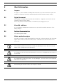
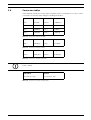
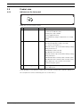
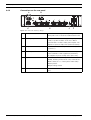
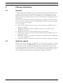
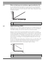
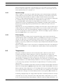
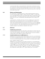
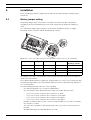
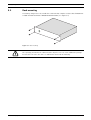
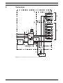
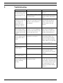
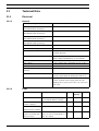
Battery Charger
PLN-24CH12 and PRS-48CH12
en
Installation and Operation manual
Battery Charger
Table of Contents | en
3
Table of Contents
1
Safety
5
2
Short Information
6
2.1
Purpose
6
2.2
Digital document
6
2.3
Intended audience
6
2.4
Related documentation
6
2.5
Alerts and notice signs
6
2.6
Conversion tables
7
3
System Overview
8
3.1
Application
8
3.2
Short description
8
3.3
Scope of delivery
8
3.4
Product view
9
3.4.1
Indicators on the front panel
3.4.2
Connections on the rear panel
10
9
4
Planning information
11
4.1
Overview
11
4.2
Amp-hour capacity
11
4.3
Effects of discharge rate on battery capacity and battery life
12
4.4
Depth of discharge (DOD)
12
4.4.1
State of charge
13
4.4.2
False capacity
13
4.5
Temperature
13
4.6
Battery self-discharging
14
4.7
Batteries
14
4.7.1
Flooded lead-acid batteries
14
4.7.2
Sealed absorbed glass mat (AGM) batteries
14
4.7.3
Sealed gel cell
15
5
Installation
16
5.1
Battery jumper setting
16
5.2
Rack mounting
17
5.3
EN54-4 labeling
18
6
Connection
19
6.1
Connecting the battery
22
6.2
Connection specifications
22
6.3
Connect the back-up power
23
6.4
Connect the auxiliary power
23
6.5
Connect the output contacts
23
6.6
Connect the temperature sensor
24
6.7
Connect the mains
24
Bosch Security Systems B.V.
Installation and Operation manual
180110011Aa | V1.1 | 2011.05
4
en | Table of Contents
Battery Charger
6.7.1
Mains power cable
24
6.7.2
Ground connection
24
7
Configuration
26
7.1
Battery charging
26
8
Operation
27
8.1
Working principles
27
8.1.1
Battery test
27
8.1.2
Battery undervoltage protection
27
8.1.3
Charging
28
8.1.4
Battery temperature compensation
29
8.2
Commissioning the system
29
9
Troubleshooting
30
10
Maintenance
31
11
Technical Data
32
11.1
Electrical
32
11.1.1
General
32
11.1.2
Fuses
32
11.2
Mechanical
33
11.3
Environmental conditions
33
11.4
Approvals and compliance with standards
33
11.4.1
Safety approvals
33
11.4.2
EMC approvals
33
11.4.3
Voice Alarm System related approvals
33
180110011Aa | V1.1 | 2011.05
Installation and Operation manual
Bosch Security Systems B.V.
Battery Charger
1
Safety | en
5
Safety
Prior to installing or operating this product, always read the Important Safety Instructions
which are available as a separate document (F.01U.120.759). These instructions are supplied
together with all equipment that can be connected to the mains supply.
Safety precautions
The battery charger is designed to be connected to the 230 Vac public distribution network.
To avoid any risk of electric shock, all interventions must be carried out with disconnected
mains supply (upstream two-pole circuit-breaker open) and disconnected battery.
Interventions with the equipment switched on are authorized only when it is impossible to
switch the equipment off. The operation must only be performed by qualified personnel.
Bosch Security Systems B.V.
Installation and Operation manual
180110011Aa | V1.1 | 2011.05
6
en | Short Information
Battery Charger
2
Short Information
2.1
Purpose
The purpose of this Installation and Operation manual is to provide information required for
installing, configuring, operating, maintaining and troubleshooting the battery charger.
2.2
Digital document
This Installation and Operation manual is also available as a digital document in the Adobe
Portable Document Format (PDF).
Refer to the product related information on www.boschsecuritysystems.com.
2.3
Intended audience
These Installation and Operation instructions are intended for installers and users of the
battery charger.
2.4
Related documentation
Voice alarm system manual.
2.5
Alerts and notice signs
Four types of alerts are used in this manual. The alert type is closely related to the effect that
may be caused if it is not observed. These alerts - from least severe effect to most severe
effect - are:
NOTICE!
Alert containing additional information. Usually, not observing a ‘notice’ does not result in
damage to the equipment or personal injuries.
CAUTION!
The equipment or the property can be damaged, or persons can be lightly injured if the alert is
not observed.
WARNING!
The equipment or the property can be seriously damaged, or persons can be severely injured
if the alert is not observed.
DANGER!
Not observing the alert can lead to severe injuries or death.
180110011Aa | V1.1 | 2011.05
Installation and Operation manual
Bosch Security Systems B.V.
Battery Charger
2.6
Short Information | en
7
Conversion tables
In this manual, SI units are used to express lengths, masses, temperatures etc. These can be
converted to non-metric units using the following information.
Imperial
Metric
Metric
Imperial
1 in =
25.4 mm
1 mm =
0.03937 in
1 in =
2.54 cm
1 cm =
0.3937 in
1 ft =
0.3048 m
1m=
3.281 ft
1 mi =
1.609 km
1 km =
0.622 mi
Table 2.1 Conversion of units of length
Imperial
Metric
Metric
Imperial
1 lb =
0.4536 kg
1 kg =
2.2046 lb
Table 2.2 Conversion of units of mass
Imperial
Metric
Metric
Imperial
1 psi =
68.95 hPa
1 hPa =
0.0145 psi
Table 2.3 Conversion of units of pressure
NOTICE!
1 hPa = 1mbar.
Fahrenheit
Celsius
°F = 9/5 (°C + 32)
°C = 5/9 (°F - 32)
Table 2.4 Conversion of units of temperature
Bosch Security Systems B.V.
Installation and Operation manual
180110011Aa | V1.1 | 2011.05
8
en | System Overview
Battery Charger
3
System Overview
3.1
Application
The PLN-24CH12 (24 Vdc) and the PRS-48CH12 (48 Vdc) battery charger is intended for a
Voice Alarm System. The battery chargers are microprocessor based devices that have been
designed to charge lead-acid batteries (back-up batteries connected to the Voice Alarm
System) and, simultaneously, to provide power to auxiliary applications.
3.2
Short description
The battery charger, which is fully compliant with EN54-4, offers a maximum charge current of
12 A.
The battery charger is two rack units (2 RU) high, and has to be installed in a 19” rack.
3.3
Scope of delivery
The battery charger is packed with the following parts:
–
1x Installation and Operation manual
–
1x Safety instructions
–
1x Mains plug (lockable)
–
6x Main output connector
–
3x Auxiliary output connector
–
1x Contact output connector
–
1x Temperature sensor connector
–
1x Temperature sensor
–
1x Main output fuse (32 A)
–
1x Auxiliary output fuse (5 A)
–
1x Mains fuse (6.3 A for PLN-24CH12) or (8 A for PRS-48CH12)
–
1x Power supply fuse (12.5 A)
–
2x Binding strip (to connect the temperature sensor to the battery cable)
–
4x Screw (for mounting the battery charger into a 19" rack)
180110011Aa | V1.1 | 2011.05
Installation and Operation manual
Bosch Security Systems B.V.
Battery Charger
System Overview | en
3.4
Product view
3.4.1
Indicators on the front panel
9
xxV Battery Charger
A
B
C
Figure 3.1 Front view of battery charger
A
Status LED
Green
Yellow
Mains status
OK
- Mains voltage threshold <165 Vac ±5% (Auto
reconnect at >185 Vac ±5%).
- Primary fuse (F1) is blown.
- Power supply is broken.
- Internal battery charger temperature is too high
(>65°C).
B
Battery status
OK
- The battery is not present.
- The internal impedance (Ri) is too high
(see section 5.1 and 8.1.1 ).
- When the mains is present and the battery voltage
during normal use is:
PLN-24CH12: <23.5 Vdc ±3%
PRS-48CH12: <47,0 Vdc ±3%
- When the mains is present and the battery voltage
during start-up is:
PLN-24CH12: Vbat ≤ 14 Vdc, Vbat ≥ 30 Vdc (±3%)
PRS-48CH12: Vbat ≤ 40 Vdc, Vbat ≥ 60 Vdc (±3%)
- When battery is connected in reverse when
commisioning the system
C
Output voltage status
OK
- No voltage on one or more output.
- Fuse (F8) broken.
Fault signalling occurs with three LEDs at the front side as well as three fail-safe outputs on
the rear panel for remote monitoring (refer to section 3.4.2 ).
Bosch Security Systems B.V.
Installation and Operation manual
180110011Aa | V1.1 | 2011.05
10
en | System Overview
3.4.2
Battery Charger
Connections on the rear panel
A
B
7
1
8
9
2
3
4
5
D
E
6
C
F
Figure 3.2 Rear view of battery charger
A
Mains power socket
Socket for connecting the battery charger to the
mains power. The socket has a built-in strain relief.
B
Auxiliary output terminals
Three terminals for connecting auxiliary outputs (5
A max.) to power modules of the Voice Alarm
System that do not have mains power inputs. The
outputs are protected by a fuse (Faux1 to Faux3).
C
Temperature sensor socket
Socket to connect the temperature sensor (see
section 6.6 ).
D
Main output terminals
Six output terminals to connect to the back-up
power terminals of VAS equipment (40 A max.).
The outputs are protected by a fuse (F1 to F6).
E
Output contacts
Fail-safe, dry contact, three-pole SPDT switch (CNC-NO), allowing 1A at 24 Vdc or 0,5 A at 120 Vac:
- Mains status (5 sec. of delay after mains fault)
- Battery status
- Output voltage status
F
Battery terminal
Terminal for connecting the battery leads (150 A
max.).
180110011Aa | V1.1 | 2011.05
Installation and Operation manual
Bosch Security Systems B.V.
Battery Charger
Planning information | en
4
Planning information
4.1
Overview
11
To find the right power back-up system for your needs, you will need to determine the exact
conditions under which you will be utilizing a back-up system. Determining the amount of
battery back-up you need for a system is not as simple as some other applications. Public
address systems do not draw a constant current. The standard defines a standby time and an
evacuation time.
In this case, it is important to pick a battery back-up that can supply the minimum amount of
power needed for a set amount of time. Then multiply that by 20 percent to give a good buffer
zone and to compensate for aging.
Proceed as follows:
1.
Determine the standby current of the system. This information is available in the voice
alarm system manual.
2.
Multiply the standby current by the standby time that the local standards call for.
Typically this is 24 hours.
3.
Compare this value to the 24 hour discharge capacity of the battery.
4.
Determine the evacuation current of the system. This information is available in the voice
alarm system manual.
5.
Multiply the evacuation current by the time that the local standards call for. Typically this
is one hour or 30 minutes.
6.
4.2
Compare this value to the 30 minute or 60 minute hour discharge capacity of the battery.
Amp-hour capacity
All batteries are rated in Amp-hours. An Amp-hour is one A for one hour, or 10 A for one tenth
of an hour, and so forth. It is Amps x hours. If you have something that draws 20 A, and use it
for 20 minutes, then the amp-hours used would be 20 (A) x .333 (hours), or 6.67 Ah. The
accepted Ah rating time period for batteries used in back-up power systems (and for nearly all
deep cycle batteries) is the "20 hour rate". This means that it is discharged down to 10.5 V
over a 20 hour period while the total actual amp-hours it supplies is measured.
Bosch Security Systems B.V.
Installation and Operation manual
180110011Aa | V1.1 | 2011.05
12
4.3
en | Planning information
Battery Charger
Effects of discharge rate on battery capacity and battery life
The rate at which a battery is discharged also has a profound effect on its capacity and life.
Figure 4.1 shows the effect of discharge rate on battery capacity. The figure shows that a
battery -when discharged at a low rate- will be able to deliver a higher capacity than a battery
discharged at a high rate.
A
B
Figure 4.1 Capacity vs discharge rate
4.4
A
Battery capacity
B
Discharge time in hours
Depth of discharge (DOD)
A battery "cycle" is one complete discharge and recharge cycle. It is usually considered to be
discharging from 100% to 20%, and then back to 100%. However, there are often ratings for
other depth of discharge cycles, the most common ones are 10%, 20%, and 50%.
Battery life is directly related to how deep the battery is cycled each time. If a battery is
discharged to 50% every day, it will last about twice as long as when it is cycled to 80% DOD.
If cycled only 10% DOD, it will last about five times as long as when it is cycled to 50%. The
most practical number to use is 50% DOD on a regular basis. This does not mean that you can
not go to 80% once in a while. It is just that when designing a system when you have some
idea of the loads, you should figure on an average DOD of around 50% for the best storage
versus cost factor.
Also, there is an upper limit: A battery that is continually cycled 5% or less will usually not last
as long as one cycled down 10%. This happens because at very shallow cycles, the lead
dioxide tends to build up in clumps on the positive plates rather than in an even film.
Figure 4.2 shows how the battery life is affected by the depth of discharge.
Figure 4.2 Battery life based on depth of discharge
A
Number of cycles
B
Daily average depth of discharge in %
180110011Aa | V1.1 | 2011.05
Installation and Operation manual
Bosch Security Systems B.V.
Battery Charger
Planning information | en
13
Battery manufacturers typically recommend that you never discharge a deep-cycle battery
below a certain percentage of its capacity. Usually 50% to 80% is recommended. The Vfinal
value determines this (see section 8.1.2 )
4.4.1
State of charge
State of charge, or conversely, the depth of discharge can be determined by measuring the
voltage and/or the specific gravity of the acid with a hydrometer. This will not tell you how
good (capacity in Ah) the battery condition is. Only a sustained load test can do that.
Voltage on a fully charged battery will read 2.12 V to 2.15 V per cell. At 50%, the reading will
be 2.03 VpC (Volts per Cell), and at 0% the reading will be 1.75 VpC or less.
Specific gravity will be about 1.265 for a fully charged cell, and 1.13 or less for a totally
discharged cell. This can vary with battery types and brands somewhat. When you buy new
batteries you should charge them up and let them sit for a while, then take a reference
measurement.
Many batteries are sealed, and hydrometer readings can not be taken. Then you must rely on
voltage. Hydrometer readings may not tell the whole story, as it takes a while for the acid to
get mixed up in wet cells. If measured right after charging, you might see 1.27 at the top of
the cell, even though it is much less at the bottom. This does not apply to gelled or absorbed
glass mat (AGM) batteries (see section 4.7.2 ).
4.4.2
False capacity
A battery can meet the voltage tests for being at full charge, yet be much lower than it's
original capacity. If plates are damaged, sulfated, or partially gone from long use, the battery
may give the appearance of being fully charged, but in reality acts like a battery of much
smaller size. This same thing can occur in gelled cells if they are overcharged and gaps or
bubbles occur in the gel. What is left of the plates may be fully functional, but with only 20%
of the plates left.
Batteries usually go bad for other reasons before reaching this point, but it is something to be
aware of if your batteries seem to test OK but lack capacity and go dead very quickly under
load.
4.5
Temperature
Battery life and battery capacity are affected by temperature. Batteries perform best in
moderate temperatures. Battery capacity is reduced as temperature goes down, and
increased as temperature goes up. (This is why a car battery dies on a cold winter morning,
even though it worked fine the previous afternoon). If the batteries are installed in an
unheated part of a building, the reduced capacity has to be taken into account when sizing
the system batteries. The standard rating for batteries is at room temperature: 25 oC (about
77 oF). At freezing, capacity is reduced by 20%. At approximately -27 oC, battery capacity
drops to 50%.
Capacity is increased at higher temperatures; At 50 oC, the battery capacity will be about 12%
higher. Even though battery capacity at high temperatures is higher, battery life is shortened.
Battery capacity is reduced by 50% at -27 oC, but battery life increases by about 60%. Battery
life is reduced at higher temperatures - for every 10 oC above 25 oC, battery life is cut in half.
This holds true for any type of lead-acid battery, whether sealed, gelled, AGM, industrial, etc.
The battery charging voltage also changes with temperature. It will vary from about 2.74 V per
cell at -40 oC to 2.3 V per cell at 50 oC. This is why temperature compensation (see section
8.1.4 ) on your battery charger must always be enabled, except for testing, maintenance, etc.
Bosch Security Systems B.V.
Installation and Operation manual
180110011Aa | V1.1 | 2011.05
14
en | Planning information
Battery Charger
Large battery banks make up a large thermal mass. Thermal mass means that because they
have so much mass, they will change internal temperature much slower than the surrounding
air temperature. For this reason, the external temperature sensor (see section 6.6 ) should be
attached in thermal contact with the battery. The sensor will then read very close to the actual
internal battery temperature.
4.6
Battery self-discharging
All lead-acid batteries supply about 2.14 V per cell when fully charged. Batteries that are
stored for long periods will eventually lose all their charge. This "leakage" or self-discharge
varies considerably with battery type, age and temperature (batteries self-discharge faster at
higher temperatures). It can range from about 1% to 15% per month. Generally, new AGM
batteries have the lowest, and old industrial (lead-antimony plates) have the highest selfdischarge.
In systems that are continually connected to some type of charging source, like the Bosch
Battery Charger, this is not a problem. However, one of the biggest killers of batteries is
sitting stored in a partly discharged state for a few months, like before commissioning. A
“float” charge should be maintained on the batteries even if they are not used (or, especially
if they are not used). Even most “dry charged” batteries (those sold without electrolyte so
they can be shipped more easily, with acid added later) will deteriorate over time. The
maximum storage life of these batteries is about two to three years.
4.7
Batteries
4.7.1
Flooded lead-acid batteries
Flooded lead-acid batteries have the longest track record in back-up use and are still used in
the majority of back-up systems. They have the longest life and the least cost per capacity. In
order to enjoy these advantages, they require regular maintenance in the form of watering,
equalizing charges and keeping the top and the terminals clean.
4.7.2
Sealed absorbed glass mat (AGM) batteries
AGM batteries are more and more used in back-up systems as their price comes down and as
more systems are getting installed that need to be maintenance free. This makes them ideally
suited for use as battery back-up. Because they are completely sealed they can not be spilled,
do not need periodic watering and emit no corrosive fumes. The electrolyte will not stratify
and no equalization charging is required.
AGM batteries are also well suited to systems that get infrequent use as they typically have
less than a 2% self-discharge rate during transport and storage. They can also be transported
easily and safely by air. They can be mounted on their side or end and are extremely vibration
resistant. AGMs come in most popular battery sizes and are available in large 2 V cells for the
ultimate in low maintenance large system storage in accordance with EN54-4. When first
introduced, because of their high cost, AGMs were mostly used in commercial installations
where maintenance was impossible, or more expensive than the price of the batteries.
180110011Aa | V1.1 | 2011.05
Installation and Operation manual
Bosch Security Systems B.V.
Battery Charger
4.7.3
Planning information | en
15
Sealed gel cell
Gelled lead-acid batteries predate the AGM batteries but are losing to AGM. They have many
of the same advantages over flooded lead-acid batteries including ease of transportation, as
the AGM type, except the gelled electrolyte in these batteries is highly viscous and
recombination of the gases generated while charging, occurs at a much slower rate. This
means that these batteries typically have to be charged slower than either flooded lead-acid
or AGM batteries.
In an emergency sound system you have a fixed amount of hours to charge the batteries from
the EN54-4. If charged at too high a rate, gas pockets form on the plates and force the gelled
electrolyte away from the plates, decreasing the capacity until the gas finds its way to the top
of the battery and is recombined with the electrolyte. For use in a system where discharge
rates are less than severe, gel batteries could be a good choice.
Bosch Security Systems B.V.
Installation and Operation manual
180110011Aa | V1.1 | 2011.05
16
5
en | Installation
Battery Charger
Installation
Before installing the battery charger into the 19" rack, the battery jumper setting must be
carried out.
5.1
Battery jumper setting
The battery charger takes every 4 hours a resistance measurement (Ri) of the battery
including connections and battery fuse if the total output current (main plus auxiliary) is
<12 A.
For each battery charger type a jumper is located at the daughter board to set trigger
thresholds for the resistance and allowed discharge current.
100
75
50
25
Figure 5.1 Location of the battery jumper of the PLN-24CH12 (similar location for the PRS-48CH12)
Jumper setting
Voltage
Threshold (Ri)
Battery capacity
Max. allowed
discharge current
75 (factory default) 24 Vdc
13 mΩ±10%
86 to 225 Ah
150 A
48 Vdc
26mΩ±10%
86 to 225 Ah
150 A
24 Vdc
20mΩ±10%
65 to 225 Ah
100 A
48 Vdc
40mΩ±10%
65 to 225 Ah
100 A
50
The jumper is set on the ‘75’ position as factory setting. Any other position of the jumper is
equal to the ‘50’ position.
Exceeding the Ri thresholds is signalled as a battery fault (see section 3.4.1 ) and means that
the battery charger with its associated battery will not have the required back-up duration in
case of mains failure.
To avoid initiating this fault, take care of the following:
–
Use authorized batteries (see Section 7 Configuration).
–
Use short battery cables with a diameter as large as possible (35 mm² max.):
–
–
For a cross-section of 10 mm², the resistance is 2 mΩ/m
–
For a cross-section of 16 mm², the resistance is 1.25 mΩ/m
–
For a cross-section of 25 mm², the resistance is 0.8 mΩ/m
–
For a cross-section of 35 mm², the resistance is 0.6 mΩ/m.
Example: for battery cables (+ and -) 1.5 m in length and with a cross-section of 10 mm²,
the resistance is 6 mΩ.
–
The connections should be realized properly in order to generate as low resistance as
possible.
–
180110011Aa | V1.1 | 2011.05
An additional battery fuse will add about 1 to 2 mΩ.
Installation and Operation manual
Bosch Security Systems B.V.
Battery Charger
5.2
Installation | en
17
Rack mounting
The battery charger has to be installed in a 19”rack that complies to Class 3k5 of EN60721-33:1995 +A2:1997 and IP30 of EN60529:1991+A1:2000. (See Figure 5.2).
Figure 5.2 Rack mounting
CAUTION!
The openings provided in the cabinet must be kept free. Do not create additional openings
because this can cause the device to malfunction and voids the warranty.
Bosch Security Systems B.V.
Installation and Operation manual
180110011Aa | V1.1 | 2011.05
18
5.3
en | Installation
Battery Charger
EN54-4 labeling
Please affix the regarding label clearly visible on the cabinet after installation.
180110011Aa | V1.1 | 2011.05
Installation and Operation manual
Bosch Security Systems B.V.
Battery Charger
6
Connection | en
19
Connection
A
Faux3
Faux2
Faux1
B
F6
F5
J
F4
C
F3
F1
F2
F1
D
9
8
G
7
6
5
4
3
H
2
1
I
K
M
E
L
F
Figure 6.1 Block diagram of the battery charger. Refer to table 6.1.
Bosch Security Systems B.V.
Installation and Operation manual
180110011Aa | V1.1 | 2011.05
20
en | Connection
Battery Charger
F
E
H
B
A
G
I
3 2 1
6
5
4
3
2
1
C
F8
M
K
D
J
F1
Figure 6.2 Top view PLN-24CH12 (24 Vdc). Refer to table 6.1.
F
E
H
B
A
G
I
3 2 1
6
5
4
3
2
1
C
F8
M
K
D
J
F1
Figure 6.3 Top view PRS-48CH12 (48 Vdc). Refer to table 6.1.
180110011Aa | V1.1 | 2011.05
Installation and Operation manual
Bosch Security Systems B.V.
Battery Charger
Connection | en
Indication
Description
A
Auxiliary output board
B
Main output board
C
Power and control board
D
Fault status LEDs
E
Temperature sensor / connection
F
Battery connection (+Batt and -Batt)
G
Auxiliary output fuses (Faux1 to Faux3) (5 A)
H
Main output fuses (F1 to F6) (32 A)
I
Output contacts connection (main, battery and output voltage status)
J
Fan
K
Daughter board
L
Battery fuse breaker (Not included. Installed outside the battery charger)
M
Battery relay
F1
Mains fuse (6.3 A for PLN-24CH12) or (8 A for PRS-48CH12)
F8
Power supply fuse (12.5 A)
21
Table 6.1 Valid for figure: 6.1, 6.2 and 6.3.
Bosch Security Systems B.V.
Installation and Operation manual
180110011Aa | V1.1 | 2011.05
22
6.1
en | Connection
Battery Charger
Connecting the battery
CAUTION!
For the PLN-24CH12 Battery Charger, the total sum of the batteries must be equal to 24 Vdc.
For the PRS-48CH12 Battery Charger, the total sum of the batteries must be equal to 48 Vdc.
When connecting multiple batteries, observe the following:
–
Only use batteries of the same voltage, capacity, type, brand and age.
–
Always connect the batteries in series. Figure 6.4 shows an example of connecting four
12 Vdc batteries to the PRS-48CH12 Battery Charger.
–
Always check the relevant standards for details on connecting multiple batteries.
–
Always use a battery fuse breaker (L) as close as possible to the battery.
The battery charger has two screw terminals for connecting the battery.
1.
Be sure that the battery fuse breaker (L) is in the off position.
2.
Connect +Batt to the plus terminal of the battery.
3.
Connect -Batt to the minus terminal of the battery.
7
8
9
1
6
2
3
4
5
6
L
Figure 6.4 Connect multiple batteries in series for PLN-48CH12 (48 Vdc) battery charger
6.2
Connection specifications
The connectors will accept the following cross sections. Refer to section 3.4.2 .
Mains plug
2.5 mm²
Battery terminal
50 mm²
Main outputs (F1 to F6))
16 mm²
Auxiliary outputs (Faux1 to Faux3)
2.5 mm²
Contact outputs
1.5 mm²
180110011Aa | V1.1 | 2011.05
Installation and Operation manual
Bosch Security Systems B.V.
Battery Charger
6.3
Connection | en
23
Connect the back-up power
The battery charger has six (main) screw terminals for connecting to the Voice Alarm System.
1.
Connect +Load (main) to the plus terminal of the system components.
2.
Connect -Load (main) to the minus terminal of the system components.
NOTICE!
Do not use the main outputs to connect remote control panels or volume overrides. For this
purpose, use the auxiliary output terminals. Refer to section 6.4 .
6.4
Connect the auxiliary power
The battery charger has pluggable Euro-style screw terminals for a 24 Vdc output (PLN24CH12) or 48 Vdc output (PRS-48CH12) to supply power for e.g.:
–
Remote Control Panels (RCP)
–
Volume overrides and general purposes
The auxiliary output terminals are protected against short circuits by means of a fuse (Faux1
to Faux3).
NOTICE!
The auxiliary outputs are intended to power modules of the Voice Alarm System that do not
have their own mains power supply. The current drawn from these auxiliary outputs should be
subtracted from the 12 A the charger can use to charge the battery. E.g. if the total auxiliary
current is 3 A, the charger should be considered a 9 A charger when calculating back-up
requirements.
6.5
Connect the output contacts
The battery charger has three fail-safe outputs on the rear panel for remote monitoring. Each
output has three terminals: Normally Closed (NC), Common (C) and Normally Open (NO).
Connection is done via a 9-pins pluggable screw terminal connector. Refer to Table 6.2 for
A
B
NO
NO
NC
NO
NC
NC
contact status. See section 3.4.1 for LED status indicators.
C
Figure 6.5 Output contacts
Status LED
Output contact
Green
Yellow
A
Mains status
C-NO
C-NC
B
Battery status
C-NO
C-NC
C
Output voltage status
C-NO
C-NC
Table 6.2 Output contact status vs LED indication
Bosch Security Systems B.V.
Installation and Operation manual
180110011Aa | V1.1 | 2011.05
24
en | Connection
6.6
Battery Charger
Connect the temperature sensor
The battery charger has one socket to connect the temperature sensor (which is packed with
the system).
1.
Plug the temperature sensor into the temperature sensor socket.
2.
Attach the sensor body close to the battery, with good thermal coupling in order to get
the correct temperature information. E.g. connect the sensor to the battery tray, or place
it between the batteries. See Figure 6.6.
7
8
9
1
6
2
3
4
5
6
Figure 6.6 Connect the temperature sensor
CAUTION!
Applied charging voltages and current are temperature dependant. Therefore always use the
temperature sensor. If the temperature sensor is not used (or not used correctly), this can
damage the battery, or reduce the lifetime of the battery. Refer to section 8.1.4 .
NOTICE!
If the temperature sensor is not connected, broken or has a short circuit, the voltage is
compensated for 25°C. Refer to section 8.1.4 .
6.7
Connect the mains
The battery charger is able to connect to 230 Vac +/- 15%.
NOTICE!
Use a mains circuit breaker to connect or disconnect the battery charger from the mains.
6.7.1
6.7.2
Mains power cable
1.
Use the supplied lockable mains connector to assemble a locally approved mains cable.
2.
Connect the mains cable to the battery charger.
Ground connection
CAUTION!
Make sure that the safety ground is connected to the battery charger via the mains power
cable.
CAUTION!
Do not make a separate ground connection to the battery.
180110011Aa | V1.1 | 2011.05
Installation and Operation manual
Bosch Security Systems B.V.
Battery Charger
Connection | en
25
CAUTION!
Do not make a separate ground connection to the 24 Vdc or 48 Vdc output terminal.
The outputs have a common return.
Bosch Security Systems B.V.
Installation and Operation manual
180110011Aa | V1.1 | 2011.05
26
en | Configuration
Battery Charger
7
Configuration
7.1
Battery charging
CAUTION!
If a mains failure occurs either on the battery charger, the connected system or on both (the
system turns on ‘back-up operating’ mode, mains not present condition) an alarm must be
generated on the Voice Alarm System.
In normal operating mode: the battery charger (re)charges the batteries and maintains them
when they are fully charged. The maximum current that can be provided to the main outputs
and auxiliary outputs is Imax a.
In back-up operating mode: the total operating current is provided by the batteries and
battery charger (when mains present) and may not exceed ‘Imax b.
Imax a
Maximum available current which may be drawn continuously while charging
the battery:
- Imax a = 12 A - Icharge.
- Icharge = C/20 (C = battery capacity)
Imax b
Maximum allowed current which may be drawn from the batteries when the
mains supply is not available on one or more of the system units:
- Imax b = 150 A if the jumper is set on '75'
- Imax b = 100 A if the jumper is set on '50' (see Figure 5.1).
Authorized batteries
If Imax b is greater than 100 A, use batteries with a capacity of 86 Ah to 225 Ah and set
daughter board jumper on ‘75’ (see Figure 5.1).
If Imax b is less than 100 A, use batteries with a capacity of 65 Ah to 225 Ah, and set daughter
board jumper on ‘50’ (see Figure 5.1).
The following batteries are approved:
–
Yuasa NPL series
–
Powersonic GB series
–
ABT TM series
–
Enersys VE series
–
Effekta BTL series
–
Long GB series.
180110011Aa | V1.1 | 2011.05
Installation and Operation manual
Bosch Security Systems B.V.
Battery Charger
Operation | en
8
Operation
8.1
Working principles
8.1.1
Battery test
27
The battery presence test is performed in the following manner:
The battery presence is tested every 30 seconds until 20 minutes after commissioning and
every 15 minutes after. If battery absence is detected a fault is generated (refer to section
3.4.1 ).
NOTICE!
If a fault is detected, the test is performed every 30 seconds, until 20 minutes after resolving
the fault.
The Ri (internal resistance) is measured every 4 hours if the mains is present on the battery
charger and if the output current is < 12A. If the Ri threshold level is exceeded a fault is
generated (refer to section 3.4.1 ). Refer to section 5.1 for Ri threshold levels.
8.1.2
Battery undervoltage protection
The voltage threshold Vfinal is 21.6 Vdc ±3% for PLN-24CH12 or 43.2 Vdc ±3% for PRS48CH12.
Discharging when the mains power (Vac) is not present on the battery charger
When discharging with the battery charger mains power (Vac) not present, the battery
charger will discharge the battery until Vfinal. At Vfinal, the undervoltage protection becomes
active: the battery charger is switched-off (latching behavior) and all outputs are shut down.
See Figure 8.1.
V
Vfloat
Vfinal
A
B
t
Figure 8.1 Discharge: battery voltage vs discharge time
A
Battery charger mains is off
B
Undervoltage Protection (UVP) active: battery charger is switched-off and all
outputs are shut down.
Discharging when the mains power (Vac) is present
When discharging with the battery charger mains power (Vac) present the following applies
for the main output:
–
Below 12 A, the battery charger will supply the output voltage on the main and the
auxiliary outputs. The battery is not drained.
–
Above 12 A, the battery charger will supply 12 A to the system. The battery supplies the
rest, and is drained until Vfinal. At Vfinal, the undervoltage protection becomes active: the
Bosch Security Systems B.V.
Installation and Operation manual
180110011Aa | V1.1 | 2011.05
28
en | Operation
Battery Charger
battery charger is switched-off (non-latching behavior) and all outputs are shut down.
See Figure 8.1.
–
When the load is decreased below 12 A the battery charger is switch-on and connects the
battery again to start the charging process.
8.1.3
Charging
Figure 8.2 and Figure 8.3 show the charger voltage and the charge current versus the time
during the charging process.
Vbatt
Vfloat
A
B
t
Figure 8.2 Charger voltage vs time
A
Bulk mode.
B
Float mode.
Ibat
A
B
t
Figure 8.3 Charge current vs time
A
Bulk mode (in this mode the current is controlled).
B
Float mode.
180110011Aa | V1.1 | 2011.05
Installation and Operation manual
Bosch Security Systems B.V.
Battery Charger
8.1.4
Operation | en
29
Battery temperature compensation
The battery charger has battery temperature compensation. The temperature is measured by
the external temperature sensor (see section 6.6 ).
Vfloat
28.5 / 56.9
27.2 / 54.4
26.2 / 52.4
-20
-10 0
10
20
30
40
50
60
70
Temp
Figure 8.4 Temperature compensation for Vfloat
The temperature compensation for Vfloat is:
For PLN-24CH12: -40 mV / oC @ 25 oC.
For PRS-48CH12: -80 mV / oC @ 25 oC.
8.2
Commissioning the system
NOTICE!
To avoid start-up problems of the battery charger, the main and auxiliary output current
should be < 12 A.
Use the following procedure to commission the system:
1.
2.
3.
Switch-on the mains circuit breaker (battery fuse breaker is off).
Check the output voltage on the main and auxiliary outputs:
–
PLN-24CH12: ≈ 27.3 Vdc
–
PRS-48CH12: ≈ 54.6 Vdc
Switch-on the battery fuse breaker L (Refer to table 6.1 ). After approx. 2.5 seconds the
battery relay is activated.
4.
The battery charger is operating correctly when the 3 LEDs on the front panel are green.
If not, refer to the troubleshoot section 9 .
Bosch Security Systems B.V.
Installation and Operation manual
180110011Aa | V1.1 | 2011.05
30
9
en | Troubleshooting
Battery Charger
Troubleshooting
Problem
Cause
Solution
Battery charger does not Mains fuse is broken.
Check / replace fuse F1 (refer to
start-up when the mains
table 6.1 ).
is connected (LEDs on
Load on battery charger outputs Disconnect load on the main and
battery charger are off).
is to high (>12 A).
auxiliary outputs until load is
<12 A.
When the battery charger Voltage of the battery is not
Check voltage on the battery
is switched on it doesn’t
between 14 V and 30 V for PLN- terminal. When the battery
start charging. The
24CH12 or 40 V and 60 V for
voltage is not between the
battery relay is not
PRS-48CH12.
specified values solve the
problem.
switched on. Battery
status LED is yellow.
No back-up power when
Probably fuse F8 is broken
Disconnect the battery and the
battery charger mains is
because of a reversed battery
mains power from battery
connected (Battery status connection when battery relay
charger. Check / replace fuse
and Output status LED is was already switched on.
F8, Main and Auxiliary fuses.
yellow).
No backup power on one On or more main or auxiliary
Check the voltage of the main
or more outputs (main or output fuses are broken.
and auxiliary outputs. The
auxiliary status LED is
measured voltage should be
yellow).
equal to the battery terminal
voltage. Replace the regarding
fuse (refer to table 6.1 ).
Mains status LED remains Refer to section 3.4.1 .
yellow.
Battery status LED
Refer to section 3.4.1 .
remains yellow.
Battery is connected in reverse. Check battery polarity on
battery terminals. When
connected in reverse solve the
problem.
Output voltage status
Refer to section 3.4.1 .
LED remains yellow.
Indicator lights are not
Problem with flat cable inside
Have qualified personnel check
illuminated while battery the battery charger.
the flat cable between the front
charger is working
panel and the controller board.
correctly.
Ensure that the battery charger
was handled with care and
without heavy bumps during
transport.
180110011Aa | V1.1 | 2011.05
Installation and Operation manual
Bosch Security Systems B.V.
Battery Charger
10
Maintenance | en
31
Maintenance
The battery charger has been designed to function without problems for a long time with a
minimum of maintenance. In order to guarantee trouble-free operation, some cleaning and
maintenance activities are required, which are described in this section.
NOTICE!
Maintenance should be done by qualified personnel only.
DANGER!
Before removing and opening the battery charger housing, make sure that:
- Mains power circuit breaker is in the off position
- Battery fuse breaker is in the off position.
- All connections are disconnected.
1.
Periodically check the batteries. Refer to the specifications and instructions of the
battery supplier.
2.
Periodically clean the battery charger with a dry, non-ragged cloth.
3.
Keep the fan and the air inlets free from dust.
WARNING!
Replacing the original battery with a battery of incorrect type may result in an explosion
hazard.
Used batteries must be disposed of in compliance with recycling requirements.
Bosch Security Systems B.V.
Installation and Operation manual
180110011Aa | V1.1 | 2011.05
32
en | Technical Data
Battery Charger
11
Technical Data
11.1
Electrical
11.1.1
General
Mains input voltage
195 - 264 Vac, 47/63 Hz
Power consumption at full load
380 W
(PLN-24CH12 Battery Charger)
Power consumption at full load
760 W
(PRS-48CH12 Battery Charger)
Maximum primary current at 195 V
2A
(PLN-24CH12 Battery Charger)
Maximum primary current at 195 V
4A
(PRS-48CH12 Battery Charger)
IEC protection class
Class I
Neutral and earthing systems
TT, TN, IT
Mains circuit breaker
Two-pole mains circuit breaker (D curve) to be
provided upstream
Battery output
24 Vdc output, 150 A battery screw terminals.
48 Vdc output, 150 A battery screw terminals.
Maximum charge current
12 A
Main outputs
6 main outputs with a maximum current of 40 A.
Auxiliary outputs
3 auxiliary outputs with a maximum current of 5 A.
Total output current (main and
150 A max.
auxiliary)
Rated output current of battery charger 12 A (this is the max. current that can be sourced
from the output without draining the batteries).
MTBF
200000 hours with external ambient temperature
of 25°C, nominal mains voltage, 48 hours full
charging (12 A / year) and for the rest of the time
load of 3 A.
11.1.2
Fuses
Location
Rating
Type
Breaking
Size
capacity
F1 mother board (mains) 6.3 A for 24 Vdc Battery charger
T
1500 A
5x20
8 A for 48 Vdc Battery charger
F1 to F6 main output
32 A
gG
10x38
5A
F
5x20
External battery fuse
Recommended fuse 100 A.
gG
breaker (not fitted with
Please check local standards for
battery charger)
max. fuse rating.
board (6 outputs)
Faux1 to Faux3 auxiliary
output board (3 outputs)
180110011Aa | V1.1 | 2011.05
Installation and Operation manual
Bosch Security Systems B.V.
Battery Charger
11.2
11.3
Technical Data | en
33
Mechanical
Dimensions (h x w x d)
44.5 x 483 x 310 mm (19” wide, 2RU high)
Weight
approx. 6 kg
Environmental conditions
Operating temperature range
-5 to +45 oC
Storage temperature range
-25 to +85 oC
Altitude
Under 76 kPa, the max operating temperature
decreases of 5°C every 10 kPa.
Cooling operates transversely.
Relative humidity (Operating and non
20 - 95% without condensation
Operating)
Make sure that the battery charger is not exposed
to sources of water or to water splashes.
11.4
Approvals and compliance with standards
This product is compliant with LV and EMC directives (immunity and emission).
11.4.1
11.4.2
Safety approvals
–
C-Tick (Australia)
–
CE (Europe)
EMC approvals
–
EN50130-4: 1995 +A1: 1998, A2:2003 Alarm systems (Immunity requirements for
components of fire, intruder and social alarm systems).
–
EN60950-1 (2006), EN61000-6-1 (2007), EN61000-6-2 (2006), EN61000-6-3 (2007),
EN61000-6-4 (2007), and EN 55022 class B (2007).
11.4.3
Voice Alarm System related approvals
–
EN54-4: 1997 and amendment A2 (February 2006): Fire detection and fire alarm systems
(Part 4: Power supply equipment).
–
CE CPD Numbers are: 0333-CPD-075381-1 (PLN-24CH12) and
0333-CPD-075383-1 (PRS-48CH12). They have been affixed in 2011.
–
EN 12101-10 class A (January 2006): Smoke and heat control systems. Part 10: power
supplies.
Bosch Security Systems B.V.
Installation and Operation manual
180110011Aa | V1.1 | 2011.05
Bosch Security Systems B.V.
Kapittelweg 10
4827 HG Breda
The Netherlands
www.boschsecurity.com
© Bosch Security Systems B.V., 2011