1
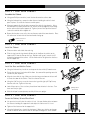
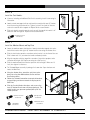
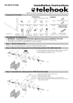
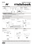
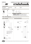
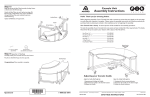
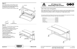
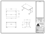
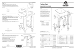
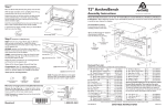
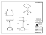
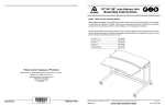
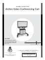
A s s e mb ly i nstr u c ti ons
Anthro Video Conferencing Cart
we l c o me
Thank you for purchasing your Anthro Video Conferencing Cart! If you
have any questions or if we can help
you in any way, please contact us at
800.325.3841.
Product
Part#
Anthro Video Conferencing Cart
DC02SM/BK5
Anthro Video Conferencing Cart w/Cabinet
DC01SM/BK5
NOTE: The Camera Mount is not included.
Warranty:
The Anthro Video Conferencing Cart has a Lifetime
Warranty.
Notices:
Technology Furniture is a trademark of Anthro Corporation.
Anthro reserves the right to modify the design and
specifications without prior notice.
Anthro Corporation® | 10450 SW Manhasset Dr. | Tualatin, OR 97062
Toll-free: 800.325.3841 | Fax: 800.325.0045 | email: [email protected] | anthro.com
Outside the U.S. | Tel: 503.691.2556 | Fax: 503.691.2409
*300-5528-00*
300-5528-00
July, 2011
PARTS LIST
Before beginning assembly of your Video Conferencing Cart, please
review the parts list to verify that your shipment is complete.
Product
Quantity Part Number
01 Top Plate
02
1
Handle Assembly
2
Handle Bar
Foam Handle Wrap
Handle Bracket
1-3/4" Flat-head Screw
225-A310-05-03-00
1
225-4311-00
04 Telehook Assembly
1
575-5073-00
05 Workstation Screw
4
325-5092-00
06 Flat Fender Washer
4
325-5629-00
07 Legs, 50" long
2
280-A304-20-01-00
08Base
1
500-A310-05-01-00
09 End Caps
1
175-A302-02-001-03
10 3/4" Screws
8
325-5106-00
11 5" Locking Casters
4
150-5084-00
12 3/4" Cap Screws
16
325-5264-00
13 1/2" Button-head Screw
22
325-5003-00
14 Tapped Rails
8
525-5037-00
15 Rubber Cable Blade, 50"
(Not shown)
2
175-5215-00
16 Cabinet (Not shown)
1
835-5455-00
17 Cabinet Handle (Not shown)
1
175-A138-10-01-03
18 Handle Fasteners (Not shown)
2
325-A129-18-01-00
CABINET COMPONENTS:
19 1/2" Button-head Screw (Not shown)8
03
325-5196-00 14
04
125-5377-00
175-5310-00
225-4421-00
325-5548-00
03 Monitor Mount Back Bracket
01
02
05
06
13
07
08
09
10
12
too ls
11
These tools are
provided for this assembly:
5/32" hex ball-end driver
5/32" hex driver bit
3/16" hex key
5/32" hex key
These tools are required but not provided:
Level
Phillips-head screwdriver
if yo ur c ar t h a s a c a b i n e t, g o to s t ep 2. i f n ot, s ta r t w i t h s t ep 1.
STEP 1 - c a r t w i t h o u t c a b i n et
Attach the Base to the Legs
¡Using the Anthro driver, install the end caps on the base with 3/4" wood screws.
¡Slide one rubber cable catcher blade into each leg.
¡Lay the legs on the floor, side by side. While one person lifts the base, the second person slides one leg into the base
(rubber blade to the back) until it reaches the bottom of the base. Attach the leg to the base with four 3/4" Cap
Screws using the 3/16" hex key. Tighten all the way. Repeat for the second leg.
¡Lock all four casters. One at a time, thread them into the holes in the base. Turn them
until they're tight. With the help of a second person, carefully lift the cart upright.
Skip ahead to Step 6.
End Caps
3/4" Cap Screw
325-5264-00
3/4" Wood Screw
325-5106-00
2
Rubber Cable Blade Top View
STEP 2 - c a r t w i t h c a b i n e t
Assemble the Cabinet
¡Using your Phillips screwdriver, install the handle onto the cabinet door.
¡Using the Anthro driver, remove the four fasteners holding the cabinet's back
panel in place. Set aside the fasteners and the panel.
¡Align one tapped rail with the holes on one of the cabinet's leg channels. Using
the Anthro driver, loosely attach one 1/2" bracket screw through the metal flange
on the cabinet and into the tapped rail. Tighten just until the tip of the fastener
reaches the outside of the tapped rail.
Leg Channel
¡Repeat for the other seven rails; there are four on each of the two channels. Place
the cabinet on its back with the lock and handle facing up.
1/2” Button-hd Screw
325-5003-00
STEP 3 - c a r t w i t h c a b i n e t
Rubber Cable Blade
Top View
Install the Cabinet
¡Slide one rubber cable blade into each leg.
¡Slide the legs into the leg channels (blades to the back) on the cabinet so the
tapped rails fit into the slots on the legs. Position each leg so it extends 2-3/4"
beyond the bottom of the cabinet. Use the Anthro driver to tighten the fasteners
for the tapped rails.
STEP 4 - c a r t w i t h c a b i n e t
Install the Base and Add the Casters
¡Using the Anthro driver, install the end caps on the base with 3/4" wood screws.
¡ Elevate the cabinet a few inches off the floor. Use some of the packing materials
included in your shipment.
¡Align the base with the legs. Make sure that the long extensions on the base will
be under the door of the cabinet. That's the front of the cart.
¡Using the 3/16" hex key, secure the base to the legs with eight 3/4" Cap Screws,
four for each side. Tighten all the way.
¡Lock all four casters. One at a time, thread them into the holes in the base. Turn
them until they're tight.
3/4" Cap Screw
325-5264-00
¡With the help of a second person, carefully lift the cart upright.
STEP 5 - c a r t w i t h c a b i n e t
Secure the Cabinet, Reinstall Back Panel
¡ Use your level to verify that the cabinet is level. Use your Anthro driver to loosen
the fasteners holding the tapped rails and adjust the cabinet until it is level.
¡Tighten all the fasteners for the tapped rails.
¡Using the Anthro driver, reinstall the back panel. Make sure that the cord wraps
are on the outside of the cabinet and the cord pass-throughs are at the bottom.
Anthro Video Conferencing Cart Assembly Instructions
3
STEP 6
Install the Cart Handles
¡ If you are including an Additional Shelf in this assembly, install it now using its
instruction.
¡Loosely attach two tapped rails to each handle assembly with two 1/2" buttonhead screws using the Anthro driver. Tighten just until the tip of the fastener
reaches the outside of the tapped rail. Repeat for the second handle.
¡Slide each handle assembly onto the cart legs until the top of the handle is 41"
above the floor and tighten. Repeat for the second handle.
1/2” Button-hd Screw
325-5003-00
STEP 7
Install the Monitor Mount and Top Plate
¡ Locate the monitor mount back bracket. Loosely attach four tapped rails to the
back of the bracket with eight 1/2" button-head screws using the Anthro driver.
¡Slide the back bracket onto the extrusions so the bracket is at the front of the cart.
Slide it down until it is just above the handle and loosely attach.
¡Align the top plate with the top of the extrusions. Attach the top plate to the
extrusions with eight 3/4" Cap Screws using the 3/16" hex key.
¡Slide the monitor mount back bracket up to the desired height. Make sure it's
level, then tighten its fasteners.
¡The Telehook Mount assembly is packaged in its own box. Open that box and
locate the Wall Plate.
¡Using the Anthro driver, attach the wall plate to the
back plate using four Workstations Screws and four
flat fender washers.
¡Follow the Telehook instructions to attach the brackets
to your display, and then to attach the display to the
Wall Plate.
¡Slide the Security Bracket into place and secure using
two 1/2" button-head screws and two nylock nuts. For
added security, use your own padlock (with 3/16" dia
shackle) instead.
1/2” Button-hd Screw
325-5003-00
Nylock Nuts
325-5259-00
3/4" Cap Screw
325-5264-00
Workstation Screw
325-5092-00
con gr at ul at i o n s ! yo u r c a r t assem b ly i s c om plete!
4
Questions? Call us at 800.325.3841 or visit anthro.com. We’re happy to walk you through the assembly!