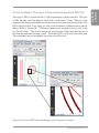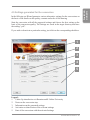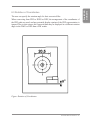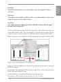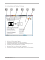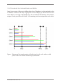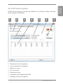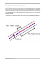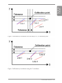
1
Andreas Ch. Kazmierczak Print2CAD 2013 OCR Manual M.Sc.Eng. Andreas Ch Kazmierczak is the founder and developer of Print2CAD Software. He has been developing software since 1982. He gained his knowledge of software development over the course of his university career followed by post grad training. Andreas attended the Technical University in Aachen, Germany where he earned his Master Degree in Engineering. During his studies at the University of Aachen, he gained foundational knowledge of numerical mathematics, 3D geometry and efficient programming techniques. He worked on doctor as an scientific assistant in the Department of Hydrology and Statistics where he created successful programs in the computer languages FORTRAN, C++ and Basic. He gave lectures and training sessions on artifical intelligence and statistics methods in hydrology. His academic career has enabled him to successfully invent conversion programs and fostered his creativity in this area. After many years of learning and training, Andreas Kazmierczak’s software is now known and used worldwide. Andreas Kazmierczak holds many patents in data security and exchange methods. In March 1993, Andreas Kazmierczak founded the company Kazmierczak Inc, specializing in commercial software for building and the exchange of data between different CAD (Computer Aided Design) systems. In 1997, Andreas Kazmierczak founded the Lions Consulting Inc. in Danzig, Poland. In 2008, Andreas Kazmierczak develop Print2Cad Software. In 2009, Andreas Kazmierczak founded the company BackToCAD Technologies LLC, located in Atlanta, Georgia. His software has been used by over 30,000 clients and over 1,000,000 users. Andreas Kazmierczak is currently a member of the Association of Consulting Engineers. The Association of Consulting Engineers VBI is the leading professional organization of independent consulting and planning engineers in Germany. The VBI has the highest requirements for professional qualifications, independent consultant status, and integrity of its members. Andreas Kazmierczak is constantly seeking advancements in CAD software to ensure the best possible upgrades. Print2CAD OCR 2013 - 2 1. Introduction 1.1 What is Print2CAD? 1.2 What is a PDF? 1.3 What is DWG? 1.4 What is DXF? 1.5 System Requirements - System Requirements - System Requirements Hardware 10 10 10 12 13 14 14 14 1.6 License Agreement § 1 Waiver of Responsibility § 2 You Agree to the Following Terms and Restrictions § 3 Copyrights 15 15 16 18 2. Installation 21 3. Conversion of Different PDF Formats 3.1 Vector Based Data Made from CAD Systems 3.2 Vector Based, Through a Plotter Interface Exported PDF File 3.3 Raster-Based PDF Files 3.4 Hybrid (Vector and Raster Based) PDF Files 22 24 25 26 27 4. Conversion with the Help of our Wizard” 4.1 Selection of the conversion method and the target formats 4.2 Selection of the files and the target directory 4.3 Details on the scale, colors, and layers 4.3.1 Details on the color of the drawing 4.3.2 Details on the scale of the drawing 4.3.3 Details on the layer structure 28 30 32 34 35 35 36 4.4 Details on the contents and quality 4.5 Settings generated for the conversion 4.6 Handling the results of the conversion 4.7 Reusing optimal settings 37 39 40 41 Print2CAD OCR 2013- 3 Print2CAD OCR 2013 Contents 5. Main Menu 5.1 File Selection 5.2 Output Files 5.3 Target Directory for Converted Files 5.4 Conversion of Directories 5.5 Version of the Target File 5.6 Wizard 5.7 Activation of the Program (depending on Purchasing Method) 5.8 Load and Save Program Settings 42 43 44 44 44 44 45 46 47 6. Optimization - Pages and Coordinates 6.1 Select of PDF pages 6.2 Scaling of Coordinates 6.3 Rotation of Coordinates 6.4 Transformation of Coordinates 6.5 Purge Bright Elements on Bright Background 48 49 50 51 52 52 7. Recognition, Purge, Layer, Colors 7.1 Recognition of the Layer Structure 7.1.1 Assign the PDF Layer Structure to DWG or DXF (if available) 7.1.2 Sort Elements on a Separate Layer According to Entity Color 7.1.3 Sort Elements on Seperate Layers According to Entity Line Weight 53 54 54 54 54 7.2 Assign Uniform Color to All Elements 7.3 Color Palette of the DWG or DXF Files 7.4 Assign Line Weight to Entities 7.5 Hatch Conversion 7.5.1 Delete all Hatches 7.5.2 Sort Hatches onto the Layer 7.5.3 Convert Boundary of Hatch 55 55 56 58 59 59 59 7.6 Generate Circles and Arcs 7.7 Purge Short Distance Polyline Vertexes 7.8 Delete Short Lines (Data Reduction) 60 62 63 8. Conversion of native PDF texts 8.1 Types of Text in PDF Files 8.2 Output Text as Text Strings 8.3 Sort Text Onto Separate Layer 8.4 Scale Factors for Blank Space Width 8.5 Scale Factors for Text Width and Height 8.6 Replace All Fonts With a SHX ot TTF Font 64 65 69 70 70 70 71 Print2CAD OCR 2013 - 4 72 73 75 75 77 78 9.3 Improvement of the Vectorization Process 9.3.1 Recognition of Horizontal and Vertical Lines 9.3.2 Recognition of Inclined Lines 9.3.3 Circle and Arc Recognition 79 79 79 80 9.4 Improving Pixel Images Before the Vectorization 9.4.1 Filling Small Holes in the Pixel Traces 9.4.2 Filling All Holes in the Pixel Traces 9.4.3 Thinning Out the Pixel Lines 9.4.4 Making the Pixel Traces Thicker 9.4.5 Removal of Free Pixels 9.4.6 Closing Slightly Opened Pixel Traces 80 81 81 81 81 82 83 9.5 Color Palette of the Vectorization 9.5.1 Black and White Vectorization 9.5.2 Color Vectorization 84 84 84 9.6 Interconnecting the Vectorization Elements to a Block 9.7 Activating the Smoothing of Lines 84 85 10. Converting into Editable Raster Pictures 10.1 Common Problems 10.2 Converting Raster Images as Horizontal Lines 10.3 Converting Raster Images as entity “Solid” 86 87 88 89 11. Thresholds for Black and White, Raster Extracting 11.1 Extracting Pixel Images to the Hard Disk 11.2 Threshold for Colors Black and White 90 91 92 Print2CAD OCR 2013- 5 Print2CAD OCR 2013 9. Vectorization of Raster Pictures 9.1 Basics of Vectorization 9.2 Choosing the vectorization process 9.2.1 Find the Center of the Pixel Traces 9.2.2 Find the Center of Pixel Traces and the Outline of Pixel Areas 9.2.3 Find the Outlines of the Pixel Areas 12. Vectorization Expert Settings 12.1 Smoothing of Polylines 12.2 Enforce Smoothing Motion 12.3 Max gap jump in pixels 12.4 Tolerance in Pixels 12.5 Conjugation Tolerance in Pixels 12.6 Minimum Pixel Length 12.7 Arc Tolerance in Pixels 12.8 Angel Sensitivity in Pixels 94 95 95 95 96 96 96 96 96 13. Configuration 13.1 Choosing The Program Language 13.2 Unit Of The Converted DWG Or DXF File 13.3 Keeping Settings After Ending The Program 13.4 Using Prefix “Print2CAD- For Converted Files 13.5 Path For Temporary Files 97 98 98 98 98 98 14. Wizard 99 15. Batch Run with Command Line Syntax of the command line Example for Print2CAD 100 100 100 16. PDF Rights 16.1 Print Permission 16.2 Permission to Extract Content 16.3 Encrypted PDF 101 101 101 101 17. PDF to Raster Conversion 17.1. Raster Target Format 17.1.1 TIFF 17.1.2 JPEG 17.1.3 BMP 17.1.4 PNG 17.1.5 GIF 17.1.6 RAW 17.1.7 EPS 102 103 103 104 104 105 105 106 106 Print2CAD OCR 2013 - 6 107 108 108 109 109 17.4 Color Type 17.4.1 Grayscale Color Space 17.4.2 RGB Color Space 17.4.3 RGBA Color Space 17.4.4 CMYK Color Space 110 110 111 111 112 17.5 OCR Definition 17.6 Conversion of selected PDF Pages 112 113 18. Analysis of a PDF File 114 19. DWG, DXF to PDF Conversion 19.1 PDF Header 19.2 Embedding Fonts 19.3 Geometry Optimization 19.4 TTF Fonts as Geometry 19.5 Zoom To Extensions 19.6 Generate PDF Layer 19.7 Output Disabled Layers 19.8 Convert Model Space 19.9 Convert Current Layout 19.10 Convert All Layouts 19.11 Convert All Layouts and Model Space 19.12 Scale Text Width 19.13 Set Line Width to 0.0 19.14 PDF Version 19.15 Paper Format 19.16 Font Directory 116 116 116 116 118 118 118 118 118 118 118 119 119 120 120 120 120 20. Normalization of Text Hights 121 Print2CAD OCR 2013- 7 Print2CAD OCR 2013 17.2. Raster Image Color Depth 17.3 Raster Image Compression 17.3.1 LZW Compression 17.3.2 G3, G4 Compression 17.3.3 JPEG Compression 21. OCR-Mode - Text, Line Type and Coordinates Recognition 122 22. OCR Text Recognition 22.1 General 22.2 Procedure 22.2.1 Breakdown Detection 22.2.2 Adjusting the Outlined Areas 22.2.3 Recognition of Pattern 22.2.3.1 Correcting Errors at the Pixel Level 22.2.3.2 Pattern Matching Mapping 22.2.3.3 Error Correction on Plane of Projection 22.2.3.4 Error Correction on Word Level 22.2.4 Manual Correction of the Recognized Texts 22.2.5 Text Recognition Quality 123 124 125 126 128 128 128 129 129 129 130 132 23. Line Type Recognition 23.1 Basics 23.2 Methods and Parameter 23.2.1 Activation 23.2.2 Parameter for Detecting Line Types 133 133 134 134 136 24. Calibration of Coordinates 24.1 Basics of the Calibration Problem 24.2 Activation of the Coordinate Calibration 140 140 142 Index 145 Print2CAD OCR 2013 - 8 Print2CAD OCR 2013 Print2CAD OCR 2013- 9 1. Introduction 1.1 What is Print2CAD? Print2CAD is an application that converts PDF files into a DWG or DXF file that can be imported and edited into any CAD system. Print2CAD also converts PDF into raster formats (TIFF, JPEG, etc.). Print2CAD also converts DWG or DXF files into PDFs. Print2CAD is a stand alone program that works independently with all CAD systems. In other words, you do not need a CAD program to use Print2CAD. Print2CAD is based on the original Adobe PDF libraries and converts files directly into DWG, DXF or raster files. The resulting files then have excellent accuracy and quality. Print2CAD also supports the newest version of PDF. Print2CAD converts files into DWG version 14, 2000-2011 or DXF version 12, 20002011. All vectors, lines, circles, arcs, surfaces, splines, text and pixel images are transferred into DWG or DXF. The pixel images can be converted into vectors, embedded or stored in separate files. Special functions generate circles and arcs. PDF layer structure is supported, or if not available in the file, this can be created on the basis of color or line widths. PDF characters are put together to create new texts. PDF properties such as line widths and line types are also converted into CAD properties. Print2CAD converts PDF colors into CAD indexed colors or full RGB colors. Print2CAD also supports TTF fonts. With multi-page PDF documents, you can specify which pages are to be converted. 1.2 What is a PDF? Portable Document Format (PDF) is a file format created in 1993 by Adobe Systems for document exchange. Adobe PDF is used for representing two-dimensional documents in a manner independent of the application software, hardware, and operating system. Each Adobe PDF file encapsulates a complete description of a fixed-layout 2D document that includes the fonts, images, and 2D vector graphics which compose the documents. Lately, 3D drawings can be embedded into PDF documents with Acrobat 3D using U3D or PRC and various other data formats. Print2CAD OCR 2013 - 10 The original imaging model of PDF was, like PostScript‘s, opaque: each object drawn on the page completely replaced anything previously marked in the same location. In PDF 1.4 the imaging model was extended to allow transparency. When transparency is used, new objects interact with previously marked objects to produce blending effects. The addition of transparency to PDF was done by means of new extensions that were designed to be ignored in products written to the PDF 1.3 and earlier specifications. As a result, files that use a small amount of transparency might view acceptably in older viewers, but files making extensive use of transparency could view completely wrongly in an older viewer without warning. The transparency extensions are based on the key concepts of transparency groups, blending modes, shape, and alpha. The model is closely aligned with the features of Adobe Illustrator version 9. The blend modes were based on those used by Adobe Photoshop at the time. The concept of a transparency group in PDF specification is independent of existing notions of “group” or “layer” in applications such as Adobe Illustrator. Those groupings reflect logical relationships among objects that are meaningful when editing those objects, but they are not part of the imaging model. Source: Wikipedia under the subject PDF License Agreement: http://creativecommons.org/licenses/by-sa/3.0/deed.de Print2CAD OCR 2013- 11 Print2CAD OCR 2013 PDF´s adoption in the early days of the format‘s history was slow. Adobe Acrobat, Adobe‘s suite for reading and creating PDFs, was not freely available; early versions of PDF had no support for external hyperlinks, reducing its usefulness on the Internet; the additional size of the PDF document compared to plain text meant significantly longer download times over the slower modems common at the time, and rendering the files was slow on less powerful machines. Additionally, there were competing formats such as Envoy, Common Ground Digital Paper, Farallon Replica and even Adobe‘s own PostScript format (.ps); in those early years, the PDF file was mainly popular in desktop publishing workflow. In 1995, AT&T Labs commenced work on another electronic document standard targeted at libraries and archives for preserving their books and documents, DjVu. This standard has evolved into the .djv/ .djvu format, which has had growing success and penetration in the online world for eBooks, catalogs, and image-sharing. 1.3 What is DWG? DWG (“drawing”) is a file format used for storing two and three dimensional design data and metadata. It is a native binary format for AutoCAD and other Autodesk Products. Almost all of CAD Systems are able to import DWG files. DWG is the native and proprietary file format for AutoCAD® and a trademark of Autodesk, Inc. The .bak (drawing backup), .dws (drawing standards), .dwt (drawing template) and .sv$ (temporary automatic save) files are also DWG files. Sample of binary DWG File: AC1021 2€ 2 € @ É@oy Xf\ # ˆÐn¶ªñH—— Ø12j šb §w– ³8L U‡õ ¹@¬<?>wæ<?> ¶Ôøhö¢¤H XÊ - Ú `Ò | w` @ow Xf NÐncªËH×— 412 :b `w . ¾G°Ã!øBám«FòÔÒ0T…V v x x<?> P Print2CAD OCR 2013 - 12 †v1 px~`8 ÊU‡4 ‡@)<?>w<?> ! ÿfº x AutoCAD DXF (Drawing Interchange Format, or Drawing Exchange Format) is a CAD data file format developed by Autodesk for enabling data interoperability between AutoCAD and other programs. DXF was originally introduced in December 1982 as part of AutoCAD 1.0 and was intended to provide an exact representation of the data in the AutoCAD native file format, DWG. Versions of AutoCAD from Release 10 (October 1988) and up support both ASCII and binary forms of DXF. Earlier versions support only ASCII. Sample of DXF File: 0 SECTION 2 HEADER 9 $ACADVER 1 AC1015 9 $ACADMAINTVER 70 6 9 $DWGCODEPAGE 3 Print2CAD OCR 2013- 13 Print2CAD OCR 2013 1.4 What is DXF? 1.5 System Requirements Input: PDF all Versions (Raster and Vector) TIFF, JPEG, GIF, PNG HPGL, HPGL-2 DWF (2D) Output: DWG - all versions (as RealDWG™ fully compatible with AutoCAD, AutoCAD LT and all other CAD systems). DXF- all versions (Version 12, 2000-2013 compatible) for all CAD systems. TIFF, JPEG, PNG, GIF, BMP, RAW PDF Patent Pendings German Patents Pending: 10 2006 015 957.8, 10 2007 003 485.9 and 10 2007 046 116.1 - System Requirements 32bit: Win 8, Win 7, Windows Vista® Enterprise, Business, Ultimate, Home Premium (SP1), Windows® XP Professional, Home Edition (SP2 or above) 64bit: Win 8, Win 7, Windows Vista® Enterprise, Business, Ultimate, Home Premium (SP1), Windows® XP Professional x64 Edition (SP2 or above) - System Requirements Hardware 32bit: Win 8, Win 7, Windows Vista: Intel® Pentium® 4 or AMD Athlon® Dual Core, 3.0 GHz or above with SSE2 Technology. Windows XP: Intel Pentium 4 or AMD Athlon Dual Core, 1.6 GHz or above with SSE2-Technology 64bit: Win 8, Win 7, AMD Athlon® 64 or Opteron® with SSE2-Technoloy; Intel® Pentium® 4 or Xeon® with Intel EM64T Support & SSE2-Technology RAM: Win 7, Win Vista: 2 GB RAM, Windows XP: 2 GB RAM Print2CAD OCR 2013 - 14 Developers: Kazmierczak Software GmbH BackToCAD Technologies, LLC Sandbühlstr. 12 400 Galleria Pkwy, Suite 1500 D-70794 Filderstadt Atlanta, GA 30339 GermanyUSA Internet: www.dxf.dewww.backtocad.com DWG is the native and proprietary file format for AutoCAD® and a trademark of Autodesk. § 1 Waiver of Responsibility Please be informed that Kazmierczak Software GmbH and BackToCAD Technologies LLC provides PDF, HPGL, TIFF, or JPEG to DWG or DXF conversion technology with Print2CAD Converter for personal use only, not for copyrighted materials you are not the owner of. Kazmierczak Software GmbH and BackToCAD Technologies LLC waives any responsibilty for possible copyright infringements. Print2CAD OCR 2013- 15 Print2CAD OCR 2013 1.6 License Agreement § 2 You Agree to the Following Terms and Restrictions 1. The transfer module of Print2CAD™ software may be installed and used on one computer only. It may not be installed on multiple computers used by different people simultaneously. 2. End Licensees agree not to alter, reverse engineer or disassemble the Software Application. End Licensees will not copy the Licensed Software except: (i) as necessary to read the Software Application from the media into the memory of a computer solely for the purpose of executing it on a single machine (whether a stand alone computer or a workstation component of a multi-terminal system), or (ii) to create an archival copy. End Licensees agree that any such copies of the Software Application shall contain the same proprietary notices which appear on and in the Software Application. 3. End Licensees may not install, access or otherwise copy or use the Software Application except as expressly authorized by this Agreement. End Licensees may not distribute, rent, loan, lease, sell, sublicense, or otherwise transfer all or any portion of the Software Application, or any rights granted in this Agreement, to any other person without the prior written consent of Licensee. End Licensees may not install or access, or allow the installation or access of, the Software Application over the Internet for the purposes of making the Software Application available to third parties, including, without limitation, use in connection with a Web hosting or similar services. End Licensees may not modify, translate, adapt, arrange, or create derivative works based on the Software Application for any purpose. End Licensees may not utilize any equipment, device, software, or other means designed to circumvent or remove any form of copy protection used by Licensee or its licensors in connection with the Software Application, or use the Software Application together with any, authorization code, serial number, or other copy protection device not supplied by Licensee or its licensors. End Licensees may not use or export the Software Application outside of the country of purchase for any reason. End Licensees acknowledge that the Software Application is the confidential information of Licensee and its suppliers, and End Licensees agree that under no circumstances may End Licensees disclose the Software Application to any third party. Title to and ownership of the intellectual property rights associated with the Software Application and any copies remain with Licensee and its suppliers. 4. End Licensees are hereby notified that Autodesk Development S.a.r.l.., Rue du Puits-Godet, 6, CH-2005 Neuchatel, Switzerland (“Autodesk”) is a third-party beneficiary to this Agreement to the extent that this Agreement contains provisions which relate to End Licensee’s use of the Software Application. Such provisions are made expressly for the benefit of Autodesk and are enforceable by Autodesk in addition to Licensee. Print2CAD OCR 2013 - 16 6. You are not entitled to loan, rent, nor to use it as the basis for software programs of your own. 7. Kazmierczak Software GmbH, Germany expressly forbids the use of Print2CAD software in applications or systems in which, as far as it is possible to judge, malfunctions of this software can be expected to cause physical damage or injury resulting in death. You may only use the program in an environment of this kind at your own risk. Kazmierczak Software GmbH shall not assume any liability whatsoever for damages or losses due to such prohibited use. 8. A guarantee shall only be granted for faults claimed within six (6) months of the purchase of this Print2CAD™ licence. Obvious defects in the software must be specified within four (4) weeks of their discovery. If the software is defective, Kazmierczak Software GmbH shall be entitled, at its own discretion, to either supply a replacement or return the purchase money. 9. You are strongly advised to test new software thoroughly in an uncritical environment before putting it to actual use. You shall bear the entire risk of being able to use the program for your intended purpose. 10. The District Court of Stuttgart, Germany shall have exclusive jurisdiction over any and all disputes arising from or related to this contract. Only substantive German law shall be applicable to this contract. 11. The Print2CAD™ software may not be made available to third parties who have connections to a data conversion service provider, an applications service provider or similar company; nor may it be used in a company for the purpose of offering services to third parties in the area of data conversion. 12. The rights granted to you by this license shall not imply that any rights are granted to third parties. Print2CAD OCR 2013- 17 Print2CAD OCR 2013 5. In no event shall Licensee or its suppliers be liable in any way for indirect, special or consequential damages of any nature, including without limitation, lost business profits, or liability or injury to third persons, whether foreseeable or not, regardless of whether Licensee or its suppliers have been advised of the possibility of such damages. § 3 Copyrights Copyright © 2006-2013 Kazmierczak® Software GmbH, Germany . All rights reserved. Contains Autodesk® RealDWG by Autodesk, Inc. Copyright© 1998-2012 Autodesk, Inc. All rights reserved. PVGOUTLIB: Copyright (c) Soft Tolls GmbH. All rights reserved. IMAGE POWER JPEG-2000: Copyright (c) 2001-2003 Michael David Adams. All rights reserved. See jasper_license.txt OpenSSL: Copyright (C) 1995-1998 Eric Young ([email protected]). All rights reserved. See openssl_license.txt. FreeType: Copyright 1996-2000 by David Turner, Robert Wilhelm and Werner Lemberg http://www.freetype.org. Icclib: Copyright (c) 1997-2002 Graeme W. Gill The Independent JPEG Group’s JPEG software: Copyright (C) 1991-1998, Thomas G. Lane. Libpng: Copyright (c) 1998-2002 Glenn Randers-Pehrson, (Version 0.96 Copyright (c) 1996, 1997 Andreas Dilger), (Version 0.88 Copyright (c) 1995, 1996 Guy Eric Schalnat, Group 42, Inc.) Libtiff: Copyright (c) 1988-1997 Sam Leffler, Copyright (c) 1991-1997 Silicon Graphics, Inc., see libtiff_license.txt. SGI Standard Template Library: Copyright (c) 1994 Hewlett-Packard Company, Copyright (c) 1996,1997 Silicon Graphics Computer Systems, Inc. Siehe sgistl_license.txt. Zlib: Copyright (C) 1995-2002 Jean-loup Gailly and Mark Adler Teigha™ for .dwg files 2003-2012 by Open Design Alliance. All rights reserved. DWG is the native and proprietary file format for AutoCAD® and a trademark of Autodesk, Inc. CxImage (c) 07/Aug/2001 <[email protected]> CxImage version 5.71 25/Apr/2003 Print2CAD OCR 2013 - 18 Print2CAD OCR 2013 Print2CAD OCR 2013- 19 Print2CAD OCR 2013 - 20 The installation is valid for all Windows 7, XP, and Vista 32 and 64 versions. The below description of the program concerns the installation CD-ROM drive D:\ and the target hard disk C:\. For other drives, the installation should be carried out similarly. a. Download and burn on CD the installation program. b. Restart your machine, then insert the CD-ROM in the drive. c. Navigate to your CD-ROM drive (e.g. Explorer). d. Start the installation by double clicking on installation program .Close the info window with “Next.” e. Answer the question of the directory where the program will be installed. Default is set to C:\Program Files\Print2CAD 2013. Installation on a network directory is not recommended because the program can use a large amount of network bandwidth and resources. f. Install the program on a local hard drive. g. Wait until the install is finished. The installation program will decompress the program files and copy them into the program directory. h. Finish the installation and restart your computer. i. Activate the program using your License ID and password. Print2CAD OCR 2013- 21 Print2CAD OCR 2013 2. Installation 3. Conversion of Different PDF Formats Invented by Adobe systems in 1993, the portable document format (PDF) is a data format for documents which can be used on many different platforms. In the last few years the PDF format has had unrivaled success and is not only for text documents but can also be implemented for blueprints from CAD software. The ground breaking idea behind the success is the scalability of the document. The scalability of PDF is possible because PDF is vector based and not pixel based. This allows you to enlarge a blueprint and still keep the original clarity of the drawing when printing. The layer technology allows one to print or omit any layers or groups of layers. The native PDF text format allows a search of a document with keywords. In short, PDF is incredible for the use of CAD. Unfortunately the possibilities of the PDF exchange are often not used. A lot of files that are called “PDF” are really not a true “PDF”, they are only a raster or pixel picture with a PDF frame. Print2CAD OCR 2013 - 22 Print2CAD OCR 2013 Figure: A true PDF file with native elements. Figure: A PDF file with no native elements. It contains only a raster picture. Print2CAD OCR 2013- 23 3.1 Vector Based Data Made from CAD Systems Vector based PDF files are the real PDF data format. The native PDF entities such as polylines, texts, native hatches are used. This kind of PDF file is created directly from a CAD application without using a plotter interface. In other words, it is exported into PDF, not “Printed To...” PDF. This kind of PDF is excellent for converting the data into DXF and DWG. The coordinates are exact enough to be used for the purpose of CAD. Figure: A vector-based, directly generated PDF file Figure: A DWG file created from a vector-based PDF file Print2CAD OCR 2013 - 24 This type of PDF is exported from a CAD programusing a plotter interface. This type of PDF has only lines and hatches, often with a resolution of 75 dpi. Whereas in the original CAD drawing coordinates can be placed in any location, plotters and printers use DPI or Dots Per Inch. Thus, there is a limit to the locations a coordinate can be placed. When a DWG is “Printed To...” PDF, the coordinates are snapped to closest „dot“ in the set “Dots Per Inch.” This clearly distorts not only the scale of the entire drawing, but of the elements within the drawing as well. This kind of PDF is still useful for conversion. The coordinates may be misaligned, but often can still be used. Figure:Vector based PDF exported through a plotter (printer) interface. Print2CAD OCR 2013- 25 Print2CAD OCR 2013 3.2 Vector Based, Through a Plotter Interface Exported PDF File 3.3 Raster-Based PDF Files A raster-based PDF is one containing only pixels. This type of PDF data does not include any native PDF elements like lines, hatches or text. The quality of the conversion is thus based on the resolution of the scan. These raster pictures have to be vectorized during a conversion to DWG or DXF. This kind of PDF is not exceptable for converting the data into DXF and DWG. The coordinates are of very bad quality and are not enough to be used for the purpose of CAD. Figure: PDF file with raster pictures. Figure: A PDF with raster pictures. Print2CAD OCR 2013 - 26 This is a combination of vector and raster formats, with all the pros and cons in one. The hybrid PDF is the real PDF file that contains the lines, texts and hatches within. This data also contains raster pictures. In this case, you have to decide how you handle the PDF raster pictures. Print2CAD offers you a lot of possibilities to vectorize raster pictures. This kind of PDF is very exceptable for converting the data into DXF and DWG. The native PDF data will convert properly. Figure: A hybrid PDF file Print2CAD OCR 2013- 27 Print2CAD OCR 2013 3.4 Hybrid (Vector and Raster Based) PDF Files 4. Conversion with the Help of our Wizard” Print2CAD 2013 has a “Wizard” that is unique throughout the world. The idea behind the Assistant is that the user views the original drawing (in the form of PDF, HPGL, DWG, TIFF or JPEG) with the aid of a built-in viewer, assesses the quality and the contents of the drawing with the aid of his own human understanding, and then answers the questions posed by the program regarding the contents and quality of the input file. Only a human being is in a position, given the state of the art of the technology that is generally available today (personal computer, Windows operating systems, 4 GB RAM, etc.) to appraise the contents of a drawing without errors in a fraction of second. He can then decide whether the drawing is a layout plan or a machine construction drawing, whether there is only text in selected areas or whether there are other elements as well, and whether the drawing is primarily with curves or straight lines. A normal PC would require several months of computing time to make an equally valid assessment and would certainly fail due to overheating. Print2CAD OCR 2013 - 28 Step 1 Step2 Step 3 Step 4 Step 5 Step 6 Print2CAD OCR 2013- 29 Print2CAD OCR 2013 As a result of the evaluation provided by the user, based on his ability to make judgments and his intellect, the program is in a position to make a number of optimal settings for the converted file. The program creates between 2 and 8 (maximum) sets of settings to use when converting the file. After the conversion the user looks at the drawings with a DWG/ DXF viewer and chooses the drawing with the best quality. The settings for the selected drawing are saved and can be reused for further conversions of files of a similar type. 4.1 Selection of the conversion method and the target formats In the first step of our Wizard the questions should be answered regarding the conversion method and the DWG/DXF target format. Our Wizard supports conversions from PDF into DWG/DXF, from HPGL2 into DWG/DXF, from DWF to DWG/DXF and from TIFF/JPEG/PNG/GIF into DWG/DXF. In the case of other formats you are directed to the main screen program. 1 2 3 4 5 Legend: 1. Video clip introduction via Kazmierczak® Online University 2. Notes on the conversion step 3. Selection of the conversion method 4. Selection of the target format Print2CAD OCR 2013 - 30 Print2CAD OCR 2013 The program supports the following format versions: PDF; all Adobe-compatible 2D versions (as of June 2012) HPGL, HP-GL/2 and HP-RTL DWF; all 2D versions (as of June 2012) TIFF, JPEG, GIFF and PNG all versions (as of June 2012) DWG versions 14 to 2013-compatible as RealDWG from Autodesk DXF versions 14 to 2013-compatible as RealDWG from Autodesk With PDF formats it is essential to make a distinction between PDFs with native PDF elements such as paths, cross-hatching, text, etc. and those PDFs with an inserted raster image of a drawing that needs to be vectorized during the conversion (with all the disadvantages involved in a conversion from raster to vector). With DWG and DXF formats as target formats of the conversion it is essential to note that Print2CAD supports RealDWG as the end format, which ensures 100% compatibility with AutoCAD programs. Print2CAD OCR 2013- 31 4.2 Selection of the files and the target directory The Wizard converts any desired number of files in one run. The converted files are saved in the target directory which is selected prior to conversion in the area below the file display area. If no target directory was selected the converted files are saved in the same directory as that of the source files. A separate file is created for each page of multi-page PDF files. 1 2 3 4 5 6 7 Legend: 1. Video clip introduction via Kazmierczak® Online University 2. Notes on the conversion step 3. List of selected files 4. File selection 5. Deleting a marked file from the list 6. Viewing the marked file with the aid of the built-in DeepView viewer 7. Selecting the location to save the converted files Print2CAD OCR 2013 - 32 The converted files have by default the prefix “Print2CAD-”. This prefix can be disabled in the configuration, but in that case any existing files that have the same name and same extension will be overwritten without any warning. Multiple converted files and the associated settings are saved in the target directory. The settings file will be designated by the extension .p4c. Please note the following points 1. The first file in the list is the most important because the settings of the Assistant are generated on the basis of the analysis of the first file and all the other files are converted with these settings. 2. All the files must be of the same type and have similar contents. Sub-divide your files into groups with the same contents (e.g. files with primarily text, primarily design drawings, primarily filled cross-hatching and areas, etc.) and convert the relevant group separately with the corresponding settings. 3. Never convert in the same group files that had been created in different ways (for example, files produced by scanners together with files produced by CAD systems). Print2CAD OCR 2013- 33 Print2CAD OCR 2013 Depending on which type of conversion had been chosen, only the appropriate file types are permitted in the selection. 4.3 Details on the scale, colors, and layers In the third step our Wizard requests details on the scale, color and layers of the drawing. Depending on the answers to these questions, suitable settings are generated for the conversion. 1 2 3 4 5 6 Legend: 1. Video clip introduction via Kazmierczak® Online University 2. Notes on the conversion step 3. View of selected File 4. Details on the color of the drawing 5. Details on the scale of the drawing 6. Details on the layer structure Print2CAD OCR 2013 - 34 Unfortunately our converter cannot rely on the color details given in the input files, especially in the case of PDF files. Very often black/white files are marked as “full color” files, which gives poor results in conversion. Here the user must examine the drawing and decide which color palette should be used. Press the “View selected file” button and view the file in the internal viewer. Then decide whether the drawing is primarily black and white, grey-scaled or colored. Here it is a matter of which color palette is important or which one predominates. If, for example, only a logo is in color and the rest is in black and white, then you can specify that the drawing is to be black and white and not colored. 4.3.2 Details on the scale of the drawing Unfortunately, the details on the scale of the drawing are not given either in PDF or in HPGL, DWF or TIFF, etc. Our Wizard requires your input on the scale. The coordinates of the drawing are scaled on the basis of these details. If no details are given on the scale, then these coordinates are output in plot or print units as appropriate. The details on the scale of the drawing are used in various ways: Method 1: Press the “View selected file” button and view the file in our internal viewer. Look in the table header of the drawing for the scale details and input the details that you have found into the wizard. If the details given in the header are correct, then the coordinates will be scaled correctly. Method 2: Press the “View selected file” button and view the file in our internal viewer. Activate the measuring function in the viewer and measure a dimensioned section in the drawing. Correspondingly input the values that were determined into the wizard. For example, if a measured section of 15.8 m (15,800 mm) results in a measured section of 311.2, then the scaling factor is 311.2:15800. Method 3: If you determine after the conversion that the coordinates show a considerable precision error, then it is necessary to carry out a calibration operation using calibration points. The calibration cannot be carried out in our Wizard. Instead you have to start the program in the main menu and start up the OCR mode. Print2CAD OCR 2013- 35 Print2CAD OCR 2013 4.3.1 Details on the color of the drawing 4.3.3 Details on the layer structure Press the “View selected file” button and view the file in our internal viewer. You can see a listing of the layers on the left-hand side of the viewer. Check whether this layer structure is actually used by switching the individual layers on and off. Then decide whether to use the existing layer structure or instead to create a new structure on the basis of the colors and types of elements. Print2CAD OCR 2013 - 36 In the fourth step our Wizard requests details on the contents and quality of the drawing. Depending on the answers to these questions, suitable settings are generated for the conversion. 1 2 3 4 5 Legend: 1. Video clip introduction via Kazmierczak® Online University 2. Notes on the conversion step 3. Settings regarding the quality of the paths (lines, arcs and circles) 4. Settings regarding the quality of the cross-hatching 5. Settings regarding the quality of the raster (bit-mapped) images Print2CAD OCR 2013- 37 Print2CAD OCR 2013 4.4 Details on the contents and quality During the analysis of the drawing the paths (lines, arcs and circles), the cross-hatching and the raster images are saved in various PDF files. The native text elements are ignored when doing this. Press the “View selected file” button and view the files. Then answer the questions on the contents and quality. It is important to decide which property predominates. Answer the question “only horizontal text” if there really is only horizontal text without other symbols or elements (lines, circles, etc.). If you answer this question incorrectly, then OCR (Optical Character Recognition) is carried out on the wrong elements, which can lead to very poor results. OCR on texts can be carried out more precisely outside the Assistant in the main screen when OCR mode has been activated. Precise delineation of the text areas is performed in this way. Print2CAD OCR 2013 - 38 In the fifth step our Wizard generates various alternative settings for the conversions on the basis of the details on the quality, contents and scale of the drawing. Start the conversion with all the suggested settings and choose the best setting on the basis of the conversion quality. The settings are saved in the target directory and have the ending “.p4c”. If you wish to deactivate a particular setting, just click on the corresponding checkbox. 1 2 3 4 5 Legend: 1. Video clip introduction via Kazmierczak® Online University 2. Notes on the conversion step 3. Information on the generated settings 4. Activation or deactivation of the relevant settings 5. Start of the conversion with the activated settings Print2CAD OCR 2013- 39 Print2CAD OCR 2013 4.5 Settings generated for the conversion 4.6 Handling the results of the conversion In the last step, the Wizard converts all the selected files using the selected settings. The files are saved in the target directory and are given the ending “-settings— [number].dwg” or “-settings—[number].dxf” as appropriate. The settings for the relevant conversion are saved under the name “-settings—[number].p4c”. The settings can be reused in the main screen. The converted DWG or DXF files can be viewed using the built-in DWG/DXF viewer. Note also the information on the converted files. 1 2 3 4 Legend: 1. Video clip introduction via Kazmierczak® Online University 2. Notes on the conversion step 3. Integrated Viewer for DWG or DXF files 4. Notes on the converted files. Print2CAD OCR 2013 - 40 The saved settings (.p4c files) can be reused in the main screen. Do this by starting the program in the main menu and load the settings with the “Load settings” function in the program. Print2CAD OCR 2013- 41 Print2CAD OCR 2013 4.7 Reusing optimal settings 5. Main Menu 1 2 3 4 5 6 7 8 1. 2. 3. 4. 5. 6. 7. 8. 9. 10. 9 10 Starting the PDF Viewer PDF File Analysis Settings - Vectorization of Raster Pictures Settings - Optimization of DWG or DXF File Optical Character Recognition (OCR) Starting the Conversion Starting the DWG/DXF Viewer Saving the Selected Program Settings Wizard for Optimum Settings Activation of the Software Print2CAD OCR 2013 - 42 Print2CAD OCR 2013 5.1 File Selection The program Print2CAD can convert multiple files in one run. All selected files will remain in their original condition after the conversion. You can choose a target directory for the converted files. If no target directory is selected, the output files will be saved in the same directory as the source files. Multi-page PDF files will convert into separate files for each page of the original file. Print2CAD OCR 2013- 43 5.2 Output Files The following output files can be created when converting: CAD files: DXF or DWG Raster files: BMP, JPG, PNG, TIFF, RAW, GIF PostScript files: EPS PDF files: PDF 5.3 Target Directory for Converted Files A target directory for the converted files should be specified. If a target directory is not selected, the output files are created in the same directory as the source files. The converted files will have the prefix “Print2CAD-.” This option can be turned off in the configuration. Note: In this case, the original files will be overwritten without warning. It is therefore best to leave the prefix on until the original data has been copied to another directory or renamed. 5.4 Conversion of Directories You may select a directory with source files. All files from this source directory are automatically converted into the chosen format, and saved to a target directory. 5.5 Version of the Target File Print2CAD converts into DWG version 14, 2000 to 2013 and DXF files version 12, 2000 to 2013 compatible. DWG is a native AutoCAD format. DXF is is a native AutoCAD data exchange format. Most CAD systems understand DWG version 2004. The DXF version 12 is understood by many CAD systems, however the quality of the DXF data is not sufficient. Print2CAD OCR 2013 - 44 With the help of the Wizard, the optimum settings for certain file types can be selected. To aide with selection of settings, the user selects the file type that best matches to his source file which when selected loads the optimum settings. Print2CAD OCR 2013- 45 Print2CAD OCR 2013 5.6 Wizard 5.7 Activation of the Program (depending on Purchasing Method) Important! The activation method depends upon how and where you purchased the program. Please follow the activation instructions you receive from our purchasing system. If you purchased the USB hardlock version of the program, then you do not have to activate it. Once you click the “Activation” button in the presence of the USB hard lock, the notice “OK! USB Code Meter found.” will appear. Print2CAD OCR 2013 - 46 When ending the application, the program saves the current program settings automatically. The same options will then be loaded when starting the program again. This option can be turned off in the Configuration Tab of the Main Menu. You can save and load all program settings by clicking the button “Save Settings” (a file with extension “p4c” will be created) and “Load Settings.” Figure: Save program settings as P4C-File Print2CAD OCR 2013- 47 Print2CAD OCR 2013 5.8 Load and Save Program Settings 6. Optimization - Pages and Coordinates 1 2 3 4 5 1. Selection of PDF pages for conversion 2. Scale coordinates with a given factor 3. Transformation of coordinates in direction X and Y 4. Do not convert very bright or white PDF entities 5.Rotate coordinates to a given degree 6. Rotate coordinates to a degree defined by the user 7. Maximum brightness of entities Print2CAD OCR 2013 - 48 6 7 The user can select which pages to convert with PDF files that have multiple pages or simply choose to convert all pages with one execution. The selected pages should be separated by using a semicolon. (e.g. 1; 4; 12; 34). To convert several pages in a row (from - to) you can use a hyphen (e.g. 12-18). Example: 1; 4; 8-10; 12 Print2CAD will convert pages 1,4,8,9,10 and 12. For PDF to raster conversion, the settings shown in the above interface will have no effect. To select specific pages of a PDF to convert into a raster file, please go to the “PDF to Raster” menu. As shown below: Print2CAD OCR 2013- 49 Print2CAD OCR 2013 6.1 Select of PDF pages 6.2 Scaling of Coordinates Coordinates in PDF files are usually in a resolution of 72dpi. 72dpi means that one inch (25.4 mm) equals 72 pixels. A PDF file can have the accuracy of 25.4/72 = 0.35 mm or 1/72 inch. A 1200 dpi resolution would make a PDF file with 18.5 * 72/1200 = 1.1 mm or 1/24 inch accuracy. These types of high-resolution PDF files are rare. Unfortunately, the scale of a PDF drawing can only be retrieved from the header of a construction plan. Find the scale in the header and input it as a scaling factor for the coordinates (e.g. the scale per the header is 1:50 and therefore the the scaling factor is 50). Figure: PDF Coordinates with resolution of 72dpi Figure: Retrieving the scale and plan size from the PDF Print2CAD OCR 2013 - 50 The user can specify the rotation angle for their converted files. When converting from PDF to DWG or DXF, the arrangement of the coordinates of the PDF paths are used, and any potential display rotation of the PDF representation is ignored. Due to this reason, the converted data may be displayed in a different rotation angle in the DWG or DXF than a PDF reader. Figure: Rotation of Coordinates Print2CAD OCR 2013- 51 Print2CAD OCR 2013 6.3 Rotation of Coordinates 6.4 Transformation of Coordinates Factors selected by the user are added to every coordinate. 6.5 Purge Bright Elements on Bright Background PDF files often include invisible white elements placed on a white background. It is possible to delete these elements during the conversion to decrease file size and conversion time. The limiting magnitude of color bightness (from 1 to 255) can be determined. Figure: Purging of bright elements on bright background Print2CAD OCR 2013 - 52 1 2 7 1. 2. 3. 4. 5. 6. 7. 3 4 5 6 8 Recognition of the Layer Structure Purge Short Distance Polyline Vertexes (Data Reduction) Delete Short Lines (Data Reduction) Generate Circles and Arcs Color Palette of the DWG or DXF Files Assign Line Weight to Entities Hatch Conversion Print2CAD OCR 2013- 53 Print2CAD OCR 2013 7. Recognition, Purge, Layer, Colors 7.1 Recognition of the Layer Structure Print2CAD offers various possibilities to assign a layer structure to the resulting DWG or DXF file. 7.1.1 Assign the PDF Layer Structure to DWG or DXF (if available) When creating a PDF file, a PDF layer structure can be assigned. Unfortunately, this feature is rarely used. The layer structure in PDF has a tree-like structure. In contrast, the layer structure in DWG or DXF is flat. Print2CAD offers the possibility to convert the tree-like structure from PDF to the flat layer structure of DWG or DXF. 7.1.2 Sort Elements on a Separate Layer According to Entity Color Print2CAD offers the possibility to create a layer structure based on the colors of PDF elements. If the recognition function is activated, all elements will be sorted by color into separate layers. The layers receive the name: Color-[Number] or Color-[RGB]. Under certain circumstances this function may create a too many layers so we recommend to change the colors to 10 index colors. This feature can be combined with the option “Sort Elements onto Separate Layers According To Entity Line Weight.” 7.1.3 Sort Elements on Seperate Layers According to Entity Line Weight Print2CAD offers the possibility to create a layer structure based on the line weight of PDF elements. If the recognition function is activated, all elements will be sorted by line weight into separate layers. The layers receive the name: Width-[Number]. This feature can be combined with the option “Sort Elements onto Seperate Layers According to Entity Color.” Important! Line width is only available in DWG or DXF file version 2004 and higher. Therefore if necessary, change the target version to 2004 or higher. Print2CAD OCR 2013 - 54 Print2CAD allows the user to assign a uniform color to all converted elements. 7.3 Color Palette of the DWG or DXF Files Print2CAD allows the user to assign the RGB values of the colors used in a PDF into the resulting DWG or DXF elements. Important! The color Black in a PDF is converted into the color White in RGB. The color White in a PDF is converted into the color White in RGB. It is possible you are working on a white background with white elements if your converted file doesn‘t show any detail on the screen. White on white will neither plot nor print. Our suggestion for a solution is simply activate the option “Assign 10 Index Colors” before converting your file. Definition of RGB color space: “An RGB color space is any additive color space based on the RGB color model. A particular RGB color space is defined by the three chromaticities of the red, green, and blue additive primaries, and can produce any chromaticity that is the triangle defined by those primary colors. The complete specification of an RGB color space also requires a white point chromaticity and a gamma correction curve. RGB is an acronym for Red, Green, Blue. An RGB color space can be easily understood by thinking of it as “all possible colors” that can be made from three colourants for red, green and blue. Imagine, for example, shining three lights together onto a white wall: one red light, one green light, and one blue light, each with dimmer switches. If only the red light is on, the wall will look red. If only the green light is on, the wall will look green. If the red and green lights are on together, the wall will look yellow. Dim the red light some and the wall will become more of a yellow-green. Dim the green light instead, and the wall will become more orange. Bringing up the blue light a bit will cause the orange to become less saturated and more whitish. In all, each setting of the three dimmer switches will produce a different result, either in color or in brightness or both. (...)” Source: Wikipedia, subject “RGB color space” Print2CAD OCR 2013- 55 Print2CAD OCR 2013 7.2 Assign Uniform Color to All Elements 7.4 Assign Line Weight to Entities The program Print2CAD allows the user to assign a PDF line weight to all DWG or DXF elements. Contrary to DWG elements having compulsory line weights, PDF elements can have any user-defined line weight. The following line weights [mm] are permitted in DWG: DWG internal designation LnWt000 LnWt005 LnWt009 LnWt013 LnWt015 LnWt018 LnWt020 LnWt025 LnWt030 LnWt035 LnWt040 LnWt050 LnWt053 LnWt060 LnWt070 LnWt080 LnWt090 LnWt100 LnWt106 LnWt120 LnWt140 LnWt158 LnWt200 LnWt210 Print2CAD OCR 2013 - 56 Line Weight 0.00 [mm] 0.05 [mm] 0.09 [mm] 0.13 [mm] 0. 15 [mm] 0. 18 [mm] 0. 20 [mm] 0. 25 [mm] 0. 30 [mm] 0. 35 [mm] 0. 40 [mm] 0. 50 [mm] 0. 53 [mm] 0. 60 [mm] 0. 70 [mm] 0. 80 [mm] 0. 90 [mm], 1.00 [mm] 1.06 [mm] 1.20 [mm] 1.40 [mm] 1.58 [mm] 2.00 [mm] 2.11 [mm] Important! Line weight is only available in DWG or DXF version 2004 and higher. If necessary, change the target version to 2004 or higher. Important! Line weights can also be defined as a hatch in PDF files. We gave this line weight the name “Line Weight Fake”. To test your PDF drawing, please follow the steps below: Turn off the line weight view in the Adobe Reader under “View Line Weights”. If the lines do not appear with line weight 0.0, then no real line weights exist, but rather hatches displaying line weight. When converting, it can be difficult to find the appropriate line weight in DWG or DXF. Figure: Native Line Weight and “Line Weight Fake” In this case the next smallest line weight will be chosen from the table of permitted DWG line weights. For Example: This means that a PDF with line weight 2.7mm will be converted into a DWG with a line weight of 2.5mm. Another difficulty is if multiple PDF lengths exist in the same area. For example: A PDF features the line weights 1.82, 2.56, 3.56mm. Print2CAD OCR 2013- 57 Print2CAD OCR 2013 Important! The PDF line weight may have any user-defined value, for example 0.27mm or 1.675 mm. The converted DWG will only feature one line weight, which in this case would be 2.11mm, which is an ISO standard line weight. Our suggestion for this would be to use the scaling factor for line weights. By using this factor, the user can enlarge or reduce the line weights in the PDF. Set the factor to 0.10 , as shown in our example above, and the results of the the line weights will be 0.18, 0.25 and 0.35mm after the conversion. Graphic: Free line weights in the PDF and the selected line weights in the DWG file 7.5 Hatch Conversion When working with PDF, there is not much difference between paths and hatches. PDF hatches are defined as paths with the annotation “filled”. This increases the load speed of the PDF file. However, DWG or DXF files may open very slowly when featuring numerous hatches. A real hatch in a DWG or DXF file features many additional attributes and qualities. Therefore a hatch may be a heavy burden for the load speed of a CAD drawing. Print2CAD OCR 2013 - 58 7.5.1 Delete all Hatches When these features are selected, the hatches are not converted, and only the boundary of the hatches are represented as polylines. If the PDF file was created using an HPGL interface the hatching boundaries may have loops. These loops are interpreted differently in DWG or DXF than in HPGL.They are possibly left empty. In such cases, delete all hatches and only output the hatching boundaries. 7.5.2 Sort Hatches onto the Layer When this feature is selected the hatches are sorted onto the given layer. 7.5.3 Convert Boundary of Hatch This function outputs all hatch boundaries as polylines. Print2CAD OCR 2013- 59 Print2CAD OCR 2013 Although AutoCAD is able to handle the impressive amount of about 10,000 hatches, it slows down the program. However, many other CAD systems are not able to handle such a large amount of hatches. Print2CAD has a maximum amount of 1000 hatches set for the conversion. If a PDF features more than 1000 hatches, only the boundaries of the remaining hatches will be converted. 7.6 Generate Circles and Arcs Many PDF files contain circles and arcs that have been converted into polylines. These polylines tend to be imprecise making it difficult to detect them as a circle or arc. Although the recognition of a polyline as a circle or arc appears to be easy when one looks at a PDF (a person can immediately recognize the circle or arc), software has to work a little harder to do this. Figure: Circle in Polyline Segments Many internal parameters were set, but there is no need to disclose all of my secrets! The recognition process works well in providing true circles. If this is not the case with your file then it was because of the lack of polylines, but rather the presence of a chain of line segments. The user can set one parameter, which is the deviation of the polyline vertexes from the radius of the circle. The parameter is set in % of the radius formula. For this you must use your intuition and experience to determine what the best parameter may be for the specific file. Print2CAD OCR 2013 - 60 Important!! When a conversion generates arcs upside down, then the radius deviation R in % was set too high. Figure: Internal Arc Parameters in Print2CAD Print2CAD OCR 2013- 61 Print2CAD OCR 2013 To generate arcs from polylines is again a very difficult task, but not impossible. The radius of arcs is subject to an internal limitation, because otherwise straight lines could be converted into arcs with a large radius. The angle alpha of the generated arcs are limited to at least 20 degrees. The convexity of arc W is also subject to restrictions. If a polyline is not converted into an arc, then it simply did not meet our internal minimum requirements. 7.7 Purge Short Distance Polyline Vertexes PDF files can contain paths with many points (vertexes). Even a large amount of path data can easily be processed in PDF, because paths do not have many parameters and properties. After the conversion in DWG or DXF, every path segment becomes a full CAD line or polyline. These single CAD elements may include many additional parameters and properties. Therefore it is advantageous to purge the polyline points during the conversion. This can be achieved by setting the following parameters: d = the minimum allowed segment of the polyline (needs to be determined) Alpha = a maximum angle between the sections. Figure: Parameters If a section is less than the parameter “d,” then the next point is deleted if the angle between the sections is smaller than “Alpha.” Assigning the angle “Alpha” helps to not truncate polyline details like corners (for example the lower left corner of figure 2 in graphic below). Print2CAD OCR 2013 - 62 Some PDF files contain paths with many small lines. This happens mostly when dottedlines have been generated in PDF files as single lines. These single lines can easily be converted to PDF as the paths do not have many parameters or properties. After the conversion in DWG or DXF, every line will be a full CAD line and may feature many additional parameters and properties. This data may strain the capacities of a CAD system and RAM. The minimum allowed line length can be set with the parameter “d.” If a line is smaller than parameter “d,” the line gets deleted. Important! Dotted lines or hatches may be deleted completely, and therefore may not be available in the created DWG or DXF file. Print2CAD OCR 2013- 63 Print2CAD OCR 2013 7.8 Delete Short Lines (Data Reduction) 8. Conversion of native PDF texts 1 1. 2. 3. 4. 5. 6. 7. 6. 2 3 Create Text as Seperate Strings Scale Factor for Virtual Blank Space Create Text as Hatches Sort All Text Onto Separate Layer Scale Factor for Text Width Scale Factor for Text Height Replace All Fonts With a TTF Font Replace All Fonts With an SHX Font Print2CAD OCR 2013 - 64 4 5 6 7 The text in PDF files can be placed as strings or individual characters. How can you find out if your PDF file contains real text? The best method is to analyse the PDF file with the analysis function of Print2CAD and see if there are any text entities indicated. Another method is to open the PDF file in a PDF Reader and zoom the text to maximum view. If the letters still have smooth edges (displaying an arc, not a polyline), your PDF file most likely features real text. If the edges of the letters are not smooth, Print2CAD will not convert the “text” to real text without activating the OCR function.The reason for this is a mathematical contradiction between the vectorization procedure and the OCR procedure (Optical Character Recognition). The two procedures can not be combined without creating severe errors. Figure: Real PDF text with smooth edge Print2CAD OCR 2013- 65 Print2CAD OCR 2013 8.1 Types of Text in PDF Files When vectorizing (OCR function not active), a polyline gets drawn along the middle of a pixel trace or the outline of a pixel area and iteratively smoothed. Then the polyline gets recognized as a circle, ellipse or spline. Figure: Vectorization procedure (generation of an ellipse) Using the OCR procedure, a pixel image gets recognized or discarded as a symbol based on its shape. Figure: OCR procedure (generation of a character 0) Print2CAD OCR 2013 - 66 Print2CAD OCR 2013 Figure: No real PDF text (raster picture) Figure: No real PDF text (text as polylines) Figure: No real PDF text (text as hatches) Print2CAD OCR 2013- 67 Another problem is created by PDF fonts as they are usually embedded in the PDF file. In DWG or DXF, the fonts have to be taken from the system. Since the fonts are embedded in PDF, the characters are no longer coded, for example per the ASCII table. PDF files often use Identity-H fonts with no rule regarding character encoding. As we are not allowed to extract fonts from a PDF to a Windows system, Print2CAD looks for similar fonts in the Windows system and defines these as substitute fonts for the DWG or DXF file getting created.. Figure: PDF fonts and DWG/DXF fonts Print2CAD OCR 2013 - 68 In PDF files, text is usually defined as separate characters or groups of characters with their own insertion points. With the help of special internal methods, Print2CAD merges characters into strings and places these strings as text in the DWG or DXF drawing. Figure: PDF characters and character groups (so called Text Runs) and CAD text Print2CAD does not reconstruct text that was fragmented into lines, arcs or hatches. Such “text” is converted faithfully back into lines or hatches in the CAD drawing. The same applies to text which is embedded as raster images in PDF. These are not displayed as text. Only real or native PDF text and characters are converted to DWG or DXF text. Figure: Real (Native) PDF text and text as a raster picture Print2CAD OCR 2013- 69 Print2CAD OCR 2013 8.2 Output Text as Text Strings 8.3 Sort Text Onto Separate Layer When activating this function, all native text gets sorted onto a predetermined layer. If there are no real text, but only polylines, hatches or raster images, the letters will not be recognized as text. 8.4 Scale Factors for Blank Space Width Text in PDF files is often placed as single letters. In this case the spaces are not available. When Print2CAD is transforming letters to text, blank spaces get recognized with the help of a substitute space width equating the letter “a.” Should the space detection does not work properly, increase or reduce the substitute space factor according to the below graphic (by trial and error): Figure: Scale Factor for Blank Space 8.5 Scale Factors for Text Width and Height If Print2CAD can’t find the fonts used in the PDF in the Windows system, Print2CAD will select a similar font. In doing so, the text width may change. A workaround for this is the use of scale factors for the text width and height. The text will be scaled by the given factor and placed left-aligned in the CAD drawing. Print2CAD OCR 2013 - 70 Enabling this option, all text styles get the same selected SHX or TTF font assigned. Figure: Fonts in PDF and in DWG or DXF Print2CAD OCR 2013- 71 Print2CAD OCR 2013 8.6 Replace All Fonts With a SHX ot TTF Font 9. Vectorization of Raster Pictures 1 1. 2. 3. 4. 5. 6. 2 3 4 5 6 Selection of Vectorization Options Smoothing of the polylines after the vectorization Generation of Horizontal, Vertical and Inclined (45 Degree) Lines Combining Vectorization Elements to a Block Selection of the Color Palette of the Vectorization Possibilities to Improve the Raster Image Prior to the Vectorization Print2CAD OCR 2013 - 72 The program can convert scanned engineering and site plans with the help of OCR or vectorization to DWG or DXF format. It is important to know that vectorization and OCR (Optical Character Recognition) are two completely different procedures that convert raster data into other formats. Vectorization calculates the middle of a pixel trace at the edge of the pixel area or polygon and iteratively smooths it. Figure: Vectorization (raster image is recognized as an ellipse) In the OCR process, a pixel image is either recognized based on shape similarity as a symbol or is discarded. Figure: OCR techniques (raster image is recognized as number 0) Print2CAD OCR 2013- 73 Print2CAD OCR 2013 9.1 Basics of Vectorization It is due to this difference of operation that the two actions, OCR and Vectorization, cannot be combined and is why the OCR mode is accessed using a tool where the user tells the program what and where the text is. The result of the vectorization depends entirely on the quality of the original raster file. If the file is of a poor quality, the resulting vectorization will likewise be poor. Figure: Example of a raster image vectorization with poor quality Left: Scanned file before vectorization Right: Vectorized DWG file Print2CAD OCR 2013 - 74 9.2.1 Find the Center of the Pixel Traces With the help of polylines, raster images can be vectorized along the center of pixel traces. After setting the polylines, the recognition of circles or splines follows. This method is suitable for most construction plans. Figure: Vectorization of a circle Figure: PDF file suitable for a vectorization along the center of the pixel traces Print2CAD OCR 2013- 75 Print2CAD OCR 2013 9.2 Choosing the vectorization process The setting “Find the Center of the Pixel Traces” provides poor results for filled areas in raster images. In this case, a line is drawn through the center of the pixel area as shown below. Figure: Incorrect vectorization of a pixel area Figure: Correct vectorization of a pixel trace Print2CAD OCR 2013 - 76 With this option, the pixel areas are converted into pixel outlines as a first step. Usually a maximum of 3 pixels remain as the pixel outline. The thickness of the outline can be specified under “Expert Settings.” After doing so, lines get drawn along the center of the pixel traces and smoothed automatically. Figure: Center of the the pixel traces and the outline of the pixel area Figure: PDF file suitable for a vectorization with contourization Figure: Contourization of a pixel area Print2CAD OCR 2013- 77 Print2CAD OCR 2013 9.2.2 Find the Center of Pixel Traces and the Outline of Pixel Areas 9.2.3 Find the Outlines of the Pixel Areas When selecting this option, the outlines of the pixel traces and areas will be converted along the boundary line and smoothed automatically. Figure: Vectorization of the outlines of pixel areas and traces Figure: PDF file suitable for a vectorization along the outlines Print2CAD OCR 2013 - 78 Print2CAD OCR 2013 9.3 Improvement of the Vectorization Process 9.3.1 Recognition of Horizontal and Vertical Lines The horizontal and vertical lines are recognized. Figure:Raster image with horizontal and vertical pixel traces 9.3.2 Recognition of Inclined Lines Recognition of n*45 degree inclined pixel traces as n*45 degree inclined lines. Figure: Recognition of 45 degree inclined lines Print2CAD OCR 2013- 79 9.3.3 Circle and Arc Recognition Detection of circles and arcs occurs when a closed polyline fits the parameters required of an arc or circle. 9.4 Improving Pixel Images Before the Vectorization PDFs with an embedded raster picture have to be improved before executing the vectorization process. This step is often necessary to ensure the quality of the converted file. Figure: Perforated pixel traces created by incorrect scanning Print2CAD OCR 2013 - 80 Print2CAD OCR 2013 9.4.1 Filling Small Holes in the Pixel Traces This setting fills the small holes in the pixel traces. 9.4.2 Filling All Holes in the Pixel Traces This setting allows all holes in the pixel traces to be filled. 9.4.3 Thinning Out the Pixel Lines This setting removes one layer of pixels from the outer edge of the pixel trace. 9.4.4 Making the Pixel Traces Thicker This setting will add a layer of pixels to the outer edge of the pixel trace. Print2CAD OCR 2013- 81 9.4.5 Removal of Free Pixels Often older scanned drawings will have free pixels. Selecting this feature will ensure the removal of these unwanted pixels, for a cleaner converted file. Figure: “Dirt” in a raster image by free pixels Figure: Removal of free pixels Print2CAD OCR 2013 - 82 Often older scanned drawings will contain open pixel traces. This setting will prompt the program to close these open spaces. Under “For Experts Only” the user is allowed to select the distance between pixels. Figure: Sligthly broken lines in a raster image Figure: Removal of slightly broken lines in a raster image Print2CAD OCR 2013- 83 Print2CAD OCR 2013 9.4.6 Closing Slightly Opened Pixel Traces 9.5 Color Palette of the Vectorization 9.5.1 Black and White Vectorization Vectorization is executed in black and white and does not support any bright pixel colors (e.g. cyan). 9.5.2 Color Vectorization The vectorization is executed in seven primary colors (index colors). First the pixel image is saved to seven files per the elementary colors, these files then get vectorized one after the other and afterwards assembled into one common DWG or DXF file. 9.6 Interconnecting the Vectorization Elements to a Block All lines, circles, and arcs are created by the vectorization and combined into a block. This block can then be moved or scaled as a unit in a CAD system. When using AutoCAD, such a block can be disassembled with the command “Explode”. Please keep in mind that AutoCAD converts polylines into splines and ellipses when having diverse block scale factors. In this case, this function should not be activated. Print2CAD OCR 2013 - 84 A scanned drawing can cause lines to wave after the vectorization. Selecting the settings “Activating Smoothing Iterations of Lines,” the wavy lines are smoothed in iterations. Figure: Vectorizing and smoothing of a pixel trace Print2CAD OCR 2013- 85 Print2CAD OCR 2013 9.7 Activating the Smoothing of Lines 10. Converting into Editable Raster Pictures Use this menu if your PDF contains pasted photos or if you want to edit raster images in DWG or DXF. 1 1. 2. 3. 4. 2 3 4 Converting PDF photos and PDF pixel traces as horizontal lines Converting PDF photos and PDF pixel traces as entities “Solid” Convert into black and white Convert using the whole color palette Print2CAD OCR 2013 - 86 A pixel image PDF file that does not have lines or areas cannot be vectorized. In such cases the pixel image should either be extracted to the hard disk or converted as horizontal lines or solids. Figure: PDF with inserted photo Print2CAD OCR 2013- 87 Print2CAD OCR 2013 10.1 Common Problems 10.2 Converting Raster Images as Horizontal Lines In this setting pixels are combined to form horizontal lines. This option is ideal for large pixel files with colorful images (e.g. photos or logos). Figure: Example conversion of a pixel image into horizontal lines Print2CAD OCR 2013 - 88 In this setting all pixel images are vectorized and embedded into the drawing as an entity “Solid” (filled square). All solids having close to the same color will be connected to create one solid. This option is ideal for colorful pictures. Figure: Example of a pixel image conversion into the DWG entity “Solid” Print2CAD OCR 2013- 89 Print2CAD OCR 2013 10.3 Converting Raster Images as entity “Solid” 11. Thresholds for Black and White, Raster Extracting In this menu you will find options that apply to all vectorization methods. 1 2 1.Extracting PDF Raster Images to the Hard Disk and embedding them as Element “Image” 2. Threshold for colors Black and White Print2CAD OCR 2013 - 90 This function allows pixel images to be extracted to the hard disk. Print2CAD takes these raster images and embeddes them or refers to them as element “Image” in a DWG or DXF file. Print2CAD OCR 2013- 91 Print2CAD OCR 2013 11.1 Extracting Pixel Images to the Hard Disk 11.2 Threshold for Colors Black and White It may be necessary of the user to define what value of brightness is white and what value of darkness is black so that only bright pixels of raster images get allocated to the color white. When vectorizing in black and white, the user-defined threshold for what is black, assigns all such pixels the color black. All remaining pixels are assigned the color white. Figure: Diagram of the transformation of bright pixels to the color white or dark pixels to the color black with the help of thresholds Print2CAD OCR 2013 - 92 Print2CAD OCR 2013 Figure: Diagram of the conversion of light gray or white pixels in the color of pixels in the color black or dark grey using thresholds. Color is gray when R = G = B. Print2CAD OCR 2013- 93 12. Vectorization Expert Settings This menu is used when you want to refine the vectorization of raster images. A good understanding of vectorization methods is necessary here. To reset the optimimum settings, please press the button “Reset to optimum” 1 2 3 1. Contouring of Pixel Areas 2. Vectorization Parameters 3. Reset to Optimal Values (Emergency Button) Print2CAD OCR 2013 - 94 The polylines must be smoothed out after vectorization. The less smooth the line prior to vectorization, the less smooth the final converted line and in fact it may be wavy or jagged depending upon the quality of the original file. 12.2 Enforce Smoothing Motion This setting caused the polylines created during vectorization to be smoothed or rendered less wavy and/or jagged. This is not a fix all, but it improves the conversion. 12.3 Max gap jump in pixels The maximum gap in pixel traces that is filled in can be adjusted. Optimally, 3 to 7 pixels. Figure: A gap jump in a pixel trace Print2CAD OCR 2013- 95 Print2CAD OCR 2013 12.1 Smoothing of Polylines 12.4 Tolerance in Pixels This function allows you to control the tolerance in pixels to determine the center of the pixel traces. 12.5 Conjugation Tolerance in Pixels This function allows you to control the tolerance in pixels to determine the center of arc-like pixel traces. 12.6 Minimum Pixel Length All pixels with a length less than or equal to the specified number get purged. 12.7 Arc Tolerance in Pixels This function allows you to control the maximum deviation of a pixel arc or circle from the calculated arc or circle. 12.8 Angel Sensitivity in Pixels This function allows you to control when a pixel trace merges into another pixel trace (like an angle). Print2CAD OCR 2013 - 96 1 1. 2. 3. 4. 5. 2 3 4 Print2CAD OCR 2013 13. Configuration 5 Language Selection (available in multiple languages) Unit selection for resulting DWG or DXF Last settings will be saved upon exiting the program. Path for temporary files Using the Prefix “Print2CAD-” for converted files Print2CAD OCR 2013- 97 13.1 Choosing The Program Language The Software Print2CAD is available in English, Spanish, Italian, French, and German. 13.2 Unit Of The Converted DWG Or DXF File This option allows the user to select the unit for measurement in their converted DWG or DXF file. The standard unit of PDF files is mm. 13.3 Keeping Settings After Ending The Program When exiting the program, the last settings are saved and automatically loaded when the program is restarted. 13.4 Using Prefix “Print2CAD- For Converted Files The user can choose to use the prefix “Print2CAD-” with their converted files. Important! Please be careful. When turning off the prefix of converted files, the target files will be overwritten without warning. 13.5 Path For Temporary Files Print2CAD uses the Windows temporary directory for its own temporary files. However, Print2CAD offers a possibility to change this directory. Just enter your own path for temporary files. The program Print2CAD will write files in this directory. Please note that the directory for temporary filess require free hard drive space with at least 10 times the size of the largest PDF file. The directory needs to be easily accessible and should not be set up on a network connection (for example a directory on a server). All temporary files in this folder will be deleted after an error-free program execution. Print2CAD OCR 2013 - 98 With the help of the wizard, the optimal settings for a specific file can be carried out. For this purpose, an image can be selected that best fits the converted file. Not all PDF files include native PDF elements such as lines and circles. Many PDF files consist only of an inserted raster files. Again, the quality of the image determines the quality of the converted file. Print2CAD OCR 2013- 99 Print2CAD OCR 2013 14. Wizard 15. Batch Run with Command Line Print2CAD can be started and controlled with the help of a command line. However, it is important to write the program fetch in quotation marks as the path may have space characters. Syntax of the command line -a: “Path and name of the settings file with an extension.p4c“ -b: “Path and name of the file selected for conversion“ -c: “Output path of the converted file“ Example for Print2CAD “c:\Programs\Print2CAD 2013\KAZMprint2cad32.exe” –a:“f:\test.p4c” –b:“f:\test. pdf”–c:“f:\” Print2CAD OCR 2013 - 100 16.1 Print Permission If the file does not have permission to extract, which is set by whoever created the PDF, then the conversion process will require the file to be “printed to...” DWG. This is checked and performed internally and behind the scenes. However, this results in the file going through a 300 DPI plot-interface which, if any element or coordinate is not directly on any one of those 300 dots then the coordinate will be moved to the closest dot, thereby losing accuracy in the final drawing. This is a permission situation, and it may be necessary to calibrate the coordinates (see Section 24). 16.2 Permission to Extract Content If the permission to Extract Content is enabled in the PDF, then a direct coordinate extraction can occur resulting in the best accuracy of coordinate placement in the final DWG. 16.3 Encrypted PDF Converting of encrypted PDFs is not supported. Print2CAD OCR 2013- 101 Print2CAD OCR 2013 16. PDF Rights 17. PDF to Raster Conversion Print2CAD OCR 2013 - 102 Print2CAD OCR 2013 17.1. Raster Target Format 17.1.1 TIFF “Tagged Image File Format (abbreviated TIFF) is a file format for storing images, popular among Apple Macintosh owners, graphic artists, the publishing industry, and both amateur and professional photographers in general. As of 2009, it is under the control of Adobe Systems. Originally created by the company Aldus for use with what was then called „desktop publishing“, the TIFF format is widely supported by image-manipulation applications, by publishing and page layout applications, by scanning, faxing, word processing, optical character recognition and other applications. Adobe Systems, which acquired Aldus, now holds the copyright to the TIFF specification. TIFF has not had a major update since 1992, several Aldus/Adobe technical notes have been published with minor extensions to the format, and several specifications have been based on the TIFF 6.0, including TIFF/EP (ISO 12234-2) and TIFF/IT (ISO 12639). TIFF is a flexible, adaptable file format for handling images and data within a single file, by including the header tags (size, definition, image-data arrangement, applied image compression) defining the image‘s geometry. For example, a TIFF file is a container holding compressed (lossy) JPEG and (lossless) PackBits compressed images. (...)” Source: Wikipedia, subject “TIFF” License Agreement: http://creativecommons.org/licenses/by-sa/3.0/ Print2CAD OCR 2013- 103 17.1.2 JPEG “In computing, JPEG (pronounced /ˈdʒeɪpɛɡ/, jay-peg) is a commonly used method of lossy compression for photographic images. The degree of compression can be adjusted, allowing a selectable tradeoff between storage size and image quality. JPEG typically achieves 10:1 compression with little perceptible loss in image quality. JPEG compression is used in a number of image file formats. JPEG is the most common image format used by digital cameras and other photographic image capture devices; along with JPEG/JFIF, it is the most common format for storing and transmitting photographic images on the World Wide Web. These format variations are often not distinguished, and are simply called JPEG. The name JPEG stands for Joint Photographic Experts Group, the name of the committee that created the JPEG standard and also other standards. It is one of two sub-groups of ISO/IEC Joint Technical Committee 1, Subcommittee 29, Working Group 1 (ISO/IEC JTC 1/SC 29/WG 1) - titled as Coding of still pictures. The group was organized in 1986, issuing the first JPEG standard in 1992, which was approved in September 1992 as ITU-T Recommendation T.81 and in 1994 as ISO/IEC 10918-1. The JPEG standard specifies the codec, which defines how an image is compressed into a stream of bytes and decompressed back into an image, but not the file format used to contain that stream. The Exif and JFIF standards define the commonly used formats for interchange of JPEG-compressed images. On the other hand, JPEG is not as well suited for line drawings and other textual or iconic graphics, where the sharp contrasts between adjacent pixels cause noticeable artifacts. Such images are better saved in a lossless graphics format such as TIFF, GIF, PNG, or a raw image format. (...) Source: Wikipedia, subject “JPEG” License Agreement: http://creativecommons.org/licenses/by-sa/3.0/ 17.1.3 BMP “The BMP file format, sometimes called bitmap or DIB file format (for device-independent bitmap), is an image file format used to store bitmap digital images, especially on Microsoft Windows and OS/2 operating systems. Many older graphical user interfaces used bitmaps in their built-in graphics subsystems; i.e. the Microsoft Windows and OS/2 platform‘s GDI subsystem, where the specific format used is the Windows and OS/2 bitmap file format, usually named with the file Print2CAD OCR 2013 - 104 Uncompressed bitmap files (such as BMP) are typically larger than compressed (with any of various methods) image file formats for the same image. For example, the 1058×1058 Wikipedia logo, which occupies about 271 KB in the lossless PNG format, takes about 3358 KB as a 24-bit BMP file. Uncompressed formats are generally unsuitable for transferring images on the Internet or other slow or capacity-limited media. (...)” Source: Wikipedia, subject “BMP” License Agreement: http://creativecommons.org/licenses/by-sa/3.0/ 17.1.4 PNG “Portable Network Graphics (PNG) is a bitmap image format that employs lossless data compression. Creation of PNG is to improve upon and replace GIF (Graphics Interchange Format) as an image-file format not requiring a patent license. Pronunciation is /ˈpɪŋ/ ping, or pee-en-gee. The PNG acronym is optionally recursive, unofficially standing for PNG‘s Not GIF. PNG supports palette-based (palettes of 24-bit RGB or 32-bit RGBA colors), grayscale, grayscale with alpha, RGB, or RGBA images. PNG used for transferring images on the Internet, not for print graphics, and so does not support none RGB color spaces (such as CMYK). (...)” Source: Wikipedia, subject “PNG” License Agreement: http://creativecommons.org/licenses/by-sa/3.0/ 17.1.5 GIF “The Graphics Interchange Format (GIF) is a bitmap image format that, was introduced by CompuServe in 1987 and has since come into widespread usage on the World Wide Web due to its wide support and portability. The format supports up to 8 bits per pixel thus allowing a single image to reference a palette of up to 256 distinct colors. The colors can be chosen from the 24-bit RGB color space. It also supports animations and allows a separate palette of 256 colors for each frame. The color limitation makes the GIF format unsuitable for reproducing color photographs and other images with continuous color, but it is well-suited for simpler images such as graphics or logos with solid areas of color. GIF images are compressed using the Lempel-Ziv-Welch (LZW) lossless data compression technique to reduce the file size without degrading the visual quality. This compression Print2CAD OCR 2013- 105 Print2CAD OCR 2013 extension of .BMP or .DIB. technique was patented in 1985. Controversy over the licensing agreement between the patent holder, Unisys, and CompuServe in 1994 spurred the development of the Portable Network Graphics (PNG) standard; since then all the relevant patents have expired. (...)” Source: Wikipedia, “GIF” License Agreement: http://creativecommons.org/licenses/by-sa/3.0/ 17.1.6 RAW “A camera raw image file contain minimally processed data from the image sensor of either a digital camera, image, or motion picture film scanner. Raw files named because they are not yet processed and are not ready to be printed or edited with a bitmap graphics editor. Normally, the image processed by a raw converter in a wide gamut internal color space where precise adjustments made before conversion to a “positive” file format such as TIFF or JPEG for storage, printing, or further manipulation, which often encodes the image in a device-dependent color space. These images are often described as “RAW image files” based on the erroneous belief that they represent a single file format. In fact there are dozens if not hundreds of raw image formats in use by different models of digital equipment (like cameras or film scanners). (...)” Source: Wikipedia, subject “RAW” License Agreement: http://creativecommons.org/licenses/by-sa/3.0/ 17.1.7 EPS “Encapsulated PostScript, or EPS, is a DSC-conforming PostScript document with additional restrictions which can be used as a graphics file format. In other words, EPS files are more or less self-contained, reasonably predictable PostScript documents that describe an image or drawing and could be placed within another PostScript document. At minimum, an EPS file contains a DSC comment, describing the rectangle containing the image described by the EPS file. Applications can use this information to lay out the page, even if they are unable to directly render the PostScript inside. EPS, together with DSC’s Open Structuring Conventions, form the basis of early versions of the Adobe Illustrator Artwork file format.” Source: Wikipedia, subject “EPS” License Agreement: http://creativecommons.org/licenses/by-sa/3.0/ Print2CAD OCR 2013 - 106 Print2CAD OCR 2013 17.2. Raster Image Color Depth “Color depth or bit depth, is a computer graphics term describing the number of bits used to represent the color of a single pixel in a bitmap image or video frame buffer. This concept is also known as bits per pixel (bpp), particularly when specified along with the number of bits used. Higher color depth gives a broader range of distinct colors. Color depth is only one aspect of color representation expressing how finely levels of color could be expressed (formally, gamut depth); the other aspect is how broad a range of colors could be expressed. The RGB color model, as used below, cannot express many colors, notably saturated colors such as yellow. Thus, the issue of color representation is not simply a sufficient color depth but also broad enough gamut.” Source: Wikipedia, subject “Color Depth” License Agreement: http://creativecommons.org/licenses/by-sa/3.0/ Print2CAD OCR 2013- 107 17.3 Raster Image Compression “Image compression is the application of data compression on digital images. In effect, the objective is to reduce redundancy of the image data in order to be able to store or transmit data in an efficient form: A chart showing the relative quality of various jpg settings and also compares saving a file as a jpg normally and using a “save for web” technique. Image compression can be lossy or lossless. Lossless compression is preferred for archival purposes and often medical imaging, technical drawings, clip art or comics. This is because lossy compression methods, especially when used at low bit rates, introduce compression artifacts. Lossy methods are especially suitable for natural images such as photos in applications where minor (sometimes imperceptible) loss of fidelity is acceptable to achieve a substantial reduction in bit rate. The lossy compression that produces imperceptible differences can be called visually lossless. (...)” Source: Wikipedia, subject “Image Compression” License Agreement: http://creativecommons.org/licenses/by-sa/3.0/ 17.3.1 LZW Compression “Lempel–Ziv–Welch (LZW) is a universal lossless data compression algorithm created by Abraham Lempel, Jacob Ziv, and Terry Welch. It was published by Welch in 1984 as an improved implementation of the LZ78 algorithm published by Lempel and Ziv in 1978. The algorithm is designed to be fast to implement but is not usually optimal because it performs only limited analysis of the data. The simple scheme described above focuses on the LZW algorithm itself. Many applications apply further encoding to the sequence of output symbols. Some package the coded stream as printable characters using some form of Binary-to-text encoding; this will increase the encoded length and decrease the compression frequency. Conversely, increased compression can often be achieved with an adaptive entropy encoder. Such a coder estimates the probability distribution for the value of the next symbol, based on the observed frequencies of values so far. A standard entropy encoding such as Huffman coding or arithmetic coding then uses shorter codes for values with higher probabilities.” Source: Wikipedia, subject “LZW Compression” License Agreement: http://creativecommons.org/licenses/by-sa/3.0/ Print2CAD OCR 2013 - 108 “Group 3 and 4 faxes are digital formats, and take advantage of digital compression methods to greatly reduce transmission times. Group 3 faxes conform to the ITU-T Recommendations T.30 and T.4. Group 3 faxes take between six and fifteen seconds to transmit a single page (not including the initial time for the fax machines to handshake and synchronize). Group 4 faxes conform to the ITU-T Recommendations T.563, T.503, T.521, T.6, T.62, T.70, T.72, T.411 to T.417. They are designed to operate over 64 kbit/s digital ISDN circuits. Their resolution is determined by the T.6 recommendation, which is a superset of the T.4 recommendation. Fax Over IP (FOIP) can transmit and receive pre-digitized documents at near realtime speeds. Scanned documents are limited to the amount of time the user takes to load the document in a scanner and for the device to process a digital file. The resolution can vary from as little as 150 DPI to 9600 DPI or more. This type of faxing is not like the e-mail to fax service that still uses fax modems. Group 3 fax machines transfer one or a few printed or handwritten pages per minute in black-and-white (bitonal) at a resolution of 204×98 (normal) or 204×196 (fine) dots per square inch. The transfer rate is 14.4 kbit/s or higher for modems and some fax machines, but fax machines support speeds beginning with 2400 bit/s and typically operate at 9600 bit/s. The transferred image formats are called ITU-T (formerly CCITT) fax group 3 or 4.” Source: Wikipedia, subject “G4 Compression” License Agreement: http://creativecommons.org/licenses/by-sa/3.0/ 17.3.3 JPEG Compression “The JPEG compression algorithm is at its best on photographs and paintings of realistic scenes with smooth variations of tone and color. For web usage, where the bandwidth used by an image is important, JPEG is very popular. JPEG/Exif is also the most common format saved by digital cameras.” Source: Wikipedia, subject “JPG Compression” License Agreement: http://creativecommons.org/licenses/by-sa/3.0/ Print2CAD OCR 2013- 109 Print2CAD OCR 2013 17.3.2 G3, G4 Compression 17.4 Color Type 17.4.1 Grayscale Color Space “In photography and computing, a grayscale or grayscale digital image is an image in which the value of each pixel is a single sample, that is, it carries only intensity information. Images of this sort, also known as black-and-white, are composed exclusively of shades of gray, varying from black at the weakest intensity to white at the strongest. Grayscale images are distinct from one-bit black-and-white images, which in the context of computer imaging are images with only the two colors, black, and white (also called bilevel or binary images). Grayscale images have many shades of gray in between. Grayscale images are also called monochromatic, denoting the absence of any chromatic variation. Grayscale images are often the result of measuring the intensity of light at each pixel in a single band of the electromagnetic spectrum (e.g. infrared, visible light, ultraviolet, etc.), and in such cases they are monochromatic proper when only a given frequency is captured. But also they can be synthesized from a full color image; see the section about converting to grayscale. R = G = B (additive mixture); see gray scale table C = M = Y (subtractive mixture)” Source: Wikipedia, subject “Grayscale Color Space” License Agreement: http://creativecommons.org/licenses/by-sa/3.0/ Print2CAD OCR 2013 - 110 “An RGB color space is any additive color space based on the RGB color model. A particular RGB color space is defined by the three chromaticities of the red, green, and blue additive primaries, and can produce any chromaticity that is the triangle defined by those primary colors. The complete specification of an RGB color space also requires a white point chromaticity and a gamma correction curve. RGB is an acronym for Red, Green, Blue. An RGB color space can be easily understood by thinking of it as “all possible colors” that can be made from three colourants for red, green, and blue. Imagine, for example, shining three lights together onto a white wall: one red light, one green light, and one blue light, each with dimmer switches. If only the red light is on, the wall will look red. If only the green light is on, the wall will look green. If the red and green lights are on together, the wall will look yellow. Dim the red light some and the wall will become more of a yellow-green. Dim the green light instead, and the wall will become more orange. Bringing up the blue light a bit will cause the orange to become less saturated and more whitish. In all, each setting of the three dimmer switches will produce a different result, either in color or in brightness or both. An LCD display can be thought of as a grid of thousands of little red, green, and blue light bulbs, each with their own dimmer switch. The gamut of the display will depend on the three colors used for the red, green, and blue lights. A wide-gamut display will have very saturated, “pure” light colors, and thus be able to display very saturated deep colors.” Source: Wikipedia, subject “RGB Color Space” License Agreement: http://creativecommons.org/licenses/by-sa/3.0/ 17.4.3 RGBA Color Space “RGBA stands for Red Green Blue Alpha. While it is sometimes described as a color space, it is actually simply a use of the RGB color model, with extra information. The alpha channel is normally used as an opacity channel. If a pixel has a value of 0% in its alpha channel, it is fully transparent (and, thus, invisible), whereas a value of 100% in the alpha channel gives a fully opaque pixel (traditional digital images). Values between 0% and 100% make it possible for pixels to show through a background like a glass (translucency), an effect not possible with simple binary (transparent or opaque) transparency. It allows easy image compositing. Alpha channel values can be expressed as a percentage, integer, or real number between 0 and 1 like RGB parameters. (...)” Source: Wikipedia, subject “RGBA Color Space” License Agreement: http://creativecommons.org/licenses/by-sa/3.0/ Print2CAD OCR 2013- 111 Print2CAD OCR 2013 17.4.2 RGB Color Space 17.4.4 CMYK Color Space “The CMYK color model (process color, four color) is a subtractive color model, used in color printing, and is also used to describe the printing process itself. CMYK refers to the four inks used in some color printing: cyan, magenta, yellow, and key black. Though it varies by print house, press operator, press manufacturer and press run, ink is typically applied in the order of the abbreviation. The “K” in CMYK stands for key since in four-color printing cyan, magenta, and yellow printing plates are carefully keyed or aligned with the key of the black key plate. Some sources suggest that the “K” in CMYK comes from the last letter in “black” and was chosen because B already means blue. However, this explanation, though plausible and useful as a mnemonic, is incorrect. The CMYK model works by partially or entirely masking colors on a lighter, usually white, background. The ink reduces the light that would otherwise be reflected. Such a model is called subtractive, because inks “subtract” brightness from white. In additive color models such as RGB, white is the “additive” combination of all primary colored lights, while black is the absence of light. In the CMYK model, it is the opposite: white is the natural color of the paper or other background, while black results from a full combination of colored inks. To save money on ink, and to produce deeper black tones, unsaturated and dark colors are produced by using black ink instead of the combination of cyan, magenta, and yellow.” Source: Wikipedia, subject “CYMK Color Space” License Agreement: http://creativecommons.org/licenses/by-sa/3.0/ 17.5 OCR Definition “Optical character recognition, usually abbreviated to OCR, is the mechanical or electronic translation of scanned images of handwritten, typewritten or printed text into machine-encoded text. It is widely used to convert books and documents into electronic files, to computerize a record-keeping system in an office, or to publish the text on a website. OCR makes it possible to edit the text, search for a word or phrase, store it more compactly, display or print a copy free of scanning artifacts, and apply techniques such as machine translation, text-to-speech and text mining to it. OCR is a field of research in pattern recognition, artificial intelligence and computer vision.” Source: Wikipedia, subject “OCR” License conditions: http://creativecommons.org/licenses/by-sa/3.0/ Print2CAD OCR 2013 - 112 For multi-page PDF documents, you can determine that only certain pages are converted to a raster file. The page numbers must be specified and separated by a comma (eg 1, 4, 12, 34). Page ranges are indicated with a hyphen (eg 12-18). Example: 1, 4, 8-10, 12 It issues the pages 1, 4, 8, 9, 10 and 12. Print2CAD OCR 2013- 113 Print2CAD OCR 2013 17.6 Conversion of selected PDF Pages 18. Analysis of a PDF File 1 2 3 1. List of files to be analyzed (#1) 2. Number of PDF page to be analyzed (#2) 3. Start Analysis (#3) Print2CAD OCR 2013 - 114 2 Print2CAD OCR 2013 1 3 1. Name of the analyzed file 2. Statistical values of the analyzed PDF file 3. Display of the separated element types of the PDF file Print2CAD OCR 2013- 115 19. DWG, DXF to PDF Conversion With the help of Print2CAD, DWG or DXF files can be converted into PDF files. DWG or DXF files can be converted directly into PDF with high quality PDF elements like text, circles, curves, lines with line types, and layers. Raster images are only displayed if they are inserted in DWG as a BMP. JPEG and TIFF files are not supported. 19.1 PDF Header The user can enter a description of the PDF file, which will later be displayed in the document properties. 19.2 Embedding Fonts When using this option, fonts are embedded into the PDF file. AutoCAD SHX-fonts will be displayed with alternative TTF fonts. 19.3 Geometry Optimization To speed up the display of the screen layout, this option will activate a simple optimization of the geometry. Print2CAD OCR 2013 - 116 2 8 9 1. 2. 3. 4. 5. 6. 7. 8. 9. 10. 11. 12. 3 10 4 11 5 6 7 12 PDF embed fonts Geometry optimization enabled SHX or TTF fonts print as geometry Zoom to the drawing limits PDF label Treatment of the layout and the model range Select Paper Size Adopt layers in the PDF Text widths scale Line width set to 0.0 Choice of PDF type Selection from its own directory with DWG, DXF fonts Print2CAD OCR 2013- 117 Print2CAD OCR 2013 1 19.4 TTF Fonts as Geometry The text with TTF fonts (Windows fonts) are recreated into simple geometry (lines, polylines). 19.5 Zoom To Extensions If this option is inactive, the last displayed section of the drawing is given out as a PDF. When activating this option, the drawing is zoomed to extensions before being converted into PDF. 19.6 Generate PDF Layer The layer assignement of the DWG or DXF is adopted in the PDF file. This option is available only for PDF version 1.4 and higher. 19.7 Output Disabled Layers By activating this option, disabled layers will also be displayed in the PDF. 19.8 Convert Model Space Only the model space of the DWG or DXF will be output. 19.9 Convert Current Layout Only the current layout (last displayed) of the DWG or DXF will be output. 19.10 Convert All Layouts All layouts of the DWG or DXF will be output as a PDF with seperate pages. Print2CAD OCR 2013 - 118 All layouts and the model space of the DWG or DXF will be output as a PDF with seperate pages. Figure: Example - a model space of DWG or DXF file 19.12 Scale Text Width By activating this function, all text widths are scaled by the given factor. Figure: Example - a layout of DWG or DXF file Print2CAD OCR 2013- 119 Print2CAD OCR 2013 19.11 Convert All Layouts and Model Space 19.13 Set Line Width to 0.0 With this function, all line widths are set to the value 0.0. 19.14 PDF Version This allows the selection of what version of PDF to be output. 19.15 Paper Format Set the dimensions of the PDF sheets here. Figure: Print margins of a PDF file 19.16 Font Directory The software Print2CAD includes original AutoCAD 2013 fonts. These fonts are saved in the program directory ...\Print2CAD 2013\Fonts. If you are using your own fonts in a DWG or DXF drawing, you can use these fonts (SHX or TTF files) by either copying them in the directory \Fonts or putting the fonts in the same directory as the DXF or DWG. The user may override the standard directory by choosing his own directory with fonts. If this is the case, Print2CAD will not search for fonts in the standard directory \Fonts anymore, but in the chosen directory. Print2CAD OCR 2013 - 120 With the aid of Print2CAD, text heights can be normalized in the converted DWG or DXF file. This is done by specifying the height ranges of text and assigning common text heights to these ranges. Existing text heights can be determined with the integrated viewer DeepView and its “Analysis” function or by clicking the button “View” and thus opening the “Properties.” The new text height should always have the smallest height of the specified range to make the text look smaller instead of bigger after the conversion. Doing so improves the optical impression (e.g. the text does not exceed the frame). 1 1. 2. 3. 4. 5. 6. 7. 2 3 4 5 6 7 Convert original Text Hight Normalize Text Hight Manual Normalization of Text Hight Height Interval New Height for Chosen Text New Layer for Chosen Text New Color for Chosen Text Print2CAD OCR 2013- 121 Print2CAD OCR 2013 20. Normalization of Text Hights 21. OCR-Mode - Text, Line Type and Coordinates Recognition Print2CAD can recognize text split into multiple lines, polylines, hatches, and raster pixels using OCR methods. Print2CAD’s OCR techniques allow the detection of dashed and dotted lines. Print2CAD’s OCR techniques also allows the accurate calibration of the coordinates of the converted drawing. OCR is an abbreviation for “Optical Character Recognition.” OCR also means symbol and pattern recognition. Before you use OCR Methods you have to activate the OCR Mode. In this mode you can convert only one file and one page at a time. 1 2 3 1. OCR-mode enable 2. Select file for OCR detections 3. OCR recognition (text, line type and coordinate detections) Print2CAD OCR 2013 - 122 Print2CAD can recognize text split into multiple lines, polylines, hatches, and raster pixels using the OCR method. 1 1. 2. 3. 4. 5. 6. 7. 2 3 4 5 6 7 Deactivation of text recognition Activate manual text recognition Indicate text areas List of text areas Preselection of text Linewidth of texts fragmented in lines Language of the text recognition Print2CAD OCR 2013- 123 Print2CAD OCR 2013 22. OCR Text Recognition 22.1 General “Optical character recognition, abbreviation is OCR, is the mechanical or electronic translation of scanned images of handwritten, typewritten or printed text into machine-encoded text. It is widely used to convert books and documents into electronic files, to computerize a record-keeping system in an office, or to publish the text on a website. OCR makes it possible to edit the text, search for a word or phrase, store it more compactly, display or print a copy free of scanning artifacts, and apply techniques such as machine translation, text-to-speech and text mining to it. OCR is a field of research in pattern recognition, artificial intelligence, and computer vision.” Quote taken from www.wikipedia.org, definition of term “OCR” License conditions: http://creativecommons.org/licenses/by-sa/3.0/ Print2CAD OCR 2013 - 124 The initial point is an image file (raster graphic) that will be generated by Print2CAD from the file being converted. This image file has the name “file name_KazOcr.tif.” It is automatically generated in the directory of the drawing being converted. When using the OCR method with text separated in lines, a clear line weight is needed. This OCR line weight can be specified in the OCR text recognition interface. It is usually set to 0.4mm. If the texts are displayed blurry in the OCR viewer, set a lower value. Another helpful tool of the OCR text recognition is the separation of the texts. A lot of PDFs feature texts as hatches. If this is the case, the separation can help to improve the text recognition by automatically discarding of distracting lines, etc. Print2CAD OCR 2013- 125 Print2CAD OCR 2013 22.2 Procedure 22.2.1 Breakdown Detection The image file is divided into relevant fields (text, captions). This allocation is performed by the user using a special editor. The division is necessary because a computer program can not with sufficient certainty sort out of a drawing file the text, lines, circles, arcs and separate the text from the rest of the drawing. Print2CAD OCR 2013 - 126 1. 2. 3. 4. 5. 6. 7. 2 3 4 5 6 7 Selecting the text areas (text and numbers separated) Zoom to size of the window Zoom window Deleting an area or back to last action Horizontal text areas Vertical text areas Baseline of text area Print2CAD OCR 2013- 127 Print2CAD OCR 2013 1 22.2.2 Adjusting the Outlined Areas The outlined text areas need to be cleansed of waste lines. This happens based on the knowledge that most lines overlap the outlined text areas, and are connected to other lines in the same area. When adjusting the text areas, all pixel traces will be deleted, which will also cut the borders of the text areas. This process happens automatically during the conversion. The graphics below can visually explain this procedure: 22.2.3 Recognition of Pattern 22.2.3.1 Correcting Errors at the Pixel Level The proximity of rough pixels to adjacent pixels can be corrected by deleting single pixels or adding missing pixels. By doing so, the recall ratio is raised when matching patterns. It is however highly dependent on the contrast of the file. Print2CAD OCR 2013 - 128 The pixel patterns of the text area are compared with patterns in the data base and then rough digitals are created 22.2.3.3 Error Correction on Plane of Projection The rough digitals are compared with dictionaries (Intelligent Character Recognition, ICR), and evaluated in regards to their probable correctness by linguistical and statistical means. According to this evaluation, the text will be output or, if required, will be further processed with modified parameters and another layout and pattern recognition. 22.2.3.4 Error Correction on Word Level Handwritten letters that can’t be recognized separately will be recognized by comparing global characteristics with dictionaries. The accurateness (Intelligent Word Recognition, IWR) decreases with the growing size of the integrated dictionaries. Print2CAD OCR 2013- 129 Print2CAD OCR 2013 22.2.3.2 Pattern Matching Mapping 22.2.4 Manual Correction of the Recognized Texts Print2CAD offers a special method allowing the user to manually correct the text areas which were recognized incorrectly. There is a possibility the computer cannot differ between “B” and “8” or number “0” and the letter “O”. Therefore, as a last step of the text recognition, an interaction between the user and the software is required. Example: The text „BAUVORHABEN“ (German Word for Building Project) is illegibly displayed in a PDF: The OCR-method of Print2CAD recognizes the text „nuvuwnu“ The user corrects it to “BAUVORHABEN”. Print2CAD OCR 2013 - 130 1. 2. 3. 4. 5. 6. 7. 2 3 4 5 6 7 List of recognized words and numbers Words recognized with OCR Bitmap (OCR base) with the text of the PDF, DWF or HPGL file Correction of a word Save the word correction Deleting a word Load last correction list if you convert the same file again Print2CAD OCR 2013- 131 Print2CAD OCR 2013 1 22.2.5 Text Recognition Quality The quality of the text recognition is, amongst other things, influenced by the following factors: - Quality of the specified text areas (depending on the user) - Extent and quality of the prototype database (given in the software) - Extent and quality of the dictionaries (given in the software) - Quality of the manual correction of the words (depending on the user) - Chromaticity, contrast, layout and font of the original file - Resolution and quality of the image file (depending on RAM) Whereas a pure pattern recognition with Print2CAD achieves a correctness in the range of 90% (every tenth figure gets recognized incorrectly), a good manual review achieves a correctness of up to 99%. Important! While text allows a higher error ratio, numbers, e.g. dimension numbers, require a thorough and repeated proofreading. Especially numbers containing “3” and “8” should be checked to ensure that “3” and “8” have not been interchanged. The same applies to “5” and “6,” as well as “1” and “7.” Important! A thorough selection of the text through text areas (text and numbers seperated) vastly improves the quality of the text recognition. Error! Results will be inaccurate Print2CAD OCR 2013 - 132 With the help of Print2CAD you can recognize fragmented lines. Print2CAD recognizes line types “dashed” and “dash dot” at any angle. 23.1 Basics One of the problems of a line type conversion from PDF, HPGL, TIFF, and/or JPEG to DWG or DXF is that lines are everywhere. The possibility to define a line with line types in PDF or HPGL files exist, but it is rarely used, because the line types appear inaccurate in the zoom factor. In these cases a static copy of the line is created using small single lines. Print2CAD 2013 has the capability to recognize similar activities and repetitive entities. This is useful in these types of conversions. With recognition there can still be some errors. In order to minimize the number of errors, the user can mark the line type areas using the internal editor before executing the conversion. Print2CAD OCR 2013- 133 Print2CAD OCR 2013 23. Line Type Recognition 23.2 Methods and Parameter 23.2.1 Activation 1 2 3 4 1. Deactivation of Line Type Recognition 2. Manual Line Type Recognition 3. Starting the Internal Editor 4. Maximum Pattern Length of the Line Recognition 5. Correction of the Line Type Areas 6. List of Line Type Areas 7. Deleting the List Print2CAD OCR 2013 - 134 5 6 7 Print2CAD OCR 2013 A line is detected only as a line by line type, if the number of dashes is greater than 4. Print2CAD OCR 2013- 135 23.2.2 Parameter for Detecting Line Types Print2CAD requires the user to identify the line types with inclination by using the internal editor. This fairly quick process will reduce the error rate significantly. To familiarize yourself with the details procedure please watch our training videos located on our website. The beginning and ending of the highlight does not necessarily need to be exact with the line in the drawing. The selection is sufficiently accurate if the red line covers the dashed lines completely. Print2CAD OCR 2013 - 136 Print2CAD OCR 2013 Figure: A PDF file with dashed and dash-dot line types Print2CAD OCR 2013- 137 Print2CAD OCR 2013 - 138 1. 2. 3. 4. 5. 6. 2 3 4 5 6 Marking the line type area Zoom to window size Zoom window Delete a highlighted area Snap point of the line Marking a line with line type Print2CAD OCR 2013- 139 Print2CAD OCR 2013 1 24. Calibration of Coordinates Print2CAD’s OCR techniques also allow the accurate calibration of the coordinates of the converted drawing. 24.1 Basics of the Calibration Problem The coordinates of PDF, HPGL, DWF, TIFF, and JPEG files often have a significant accuracy error. This error is mostly created by exporting entities in a raster of 72 dpi (dots per inch). Print2CAD features settings to allow the user to calibrate the coordinates of the converted drawing. This calibration happens in the horizontal and vertical directions. The calibration of coordinates is based on pattern recognition methods. When calibrating the coordinates, a special feature is used that keeps the horizontal and vertical lines the same after the calibration. Figure: Accuracy error dX and dY in a PDF file created by the 72 dpi resolution Print2CAD OCR 2013 - 140 Print2CAD OCR 2013 Figure: Calibration of coordinates with the help of a Y, X calibration point Figure: Calibration of coordinates using the Y coordinate Print2CAD OCR 2013- 141 24.2 Activation of the Coordinate Calibration 1 1. 2. 3. 4. 5. 6. 7. 2 3 4 5 Coordinate Calibration Automatic Calibration of Coordinates Based on Drawing Scale Manual Calibration of Coordinates Create New List of Coordinates Tolerance of the Coordinate Calibration List of Calibration Coordinates View or Change Existing List of Coordinates Print2CAD OCR 2013 - 142 6 7 Print2CAD OCR 2013 Print2CAD OCR 2013- 143 1 1. 2. 3. 4. 5. 6. 2 3 4 Activation of the input coordinates of the calibration Zoom up to the limits of the drawing Zoom window Delete a field or back of the last action X Value Calibrating Point Y Value Calibrating Point Print2CAD OCR 2013 - 144 5 6 Print2CAD OCR 2013 Index A Acrobat 11 Adjusting 128 Adobe 10, 22, 31, 103 Adobe Reader 57 Analysis 114 Apple Macintosh 103 Areas 77 ASCII 68 AT&T Labs 11 AutoCAD 12, 13, 31, 59, 84, 116 Autodesk 12 B bit depth 107 Bitmap 131 Blank Space Width 70 BMP 44, 104, 116 Breakdown Detection 126 C CAD 10, 12, 22, 24, 25, 26, 33, 44, 58, 62, 63, 69, 70, 84 Caddie 12 Calibration 140, 142 Calibration of Coordinates 140 CMYK 105, 112 Color 84 Color Depth 107 colors 34 Colors 53 Compression 108, 109 Configuration 97 Contouring 94 Contourization 77 Print2CAD OCR 2013- 145 conversion 30, 39 Conversion 28, 58, 64, 102, 116 Converting 86, 88 coordinates 48 Coordinates 50, 51, 52 Correction 129 Current Layout 118 D DIB 104 dpi 25, 50 DPI 109 DSC 106 DWF 14, 30, 35, 131, 140 dwg 40 DWG 10, 12, 14, 24, 25, 26, 27, 28, 30, 40, 42, 44, 51, 53, 54, 55, 56, 58, 62, 63, 68, 69, 71, 73, 84, 86, 89, 91, 97, 98, 101, 116, 133, 140 dxf 40 DXF 10, 13, 14, 24, 25, 26, 27, 30, 40, 42, 44, 51, 53, 54, 55, 56, 58, 62, 6 3, 68, 69, 71, 73, 84, 86, 91, 97, 98, 101, 116, 133 DXGF 40 E Editable 86 embedded 68 Embedding 90, 116 EPS 44, 106 Extracting 90, 91 F FOIP 109 font 70 fonts 68 Fonts 64, 116 Free Pixels 82 Print2CAD OCR 2013 - 146 Print2CAD OCR 2013 G G3 109 G4 109 GDI 104 GIF 14, 30, 44, 105 H Handwritten 129 hatch 125 Horizontal Lines 88 HPGL 14, 28, 31, 35, 131, 133, 140 HPGL-2 14 HPGL2 30 HP-RTL 31 Human Intellect 28 Human Intellect Assistant 32, 34, 39, 40 Hybrid 27 I ICR 129 Illustrator 11 Improving 80 Inclination 136 IntelliCAD 12 ITU-T 109 J JFIF 104 JPEG 10, 14, 28, 30, 101, 103, 104, 106, 109, 116, 133, 140 JPG 44 Print2CAD OCR 2013- 147 K Kazmierczak® 30, 32, 34, 37, 39, 40 L Layer 53, 118 layers 34 Layer Structure 53 Layouts 118 LCD 111 Line Type Areas 134 Line Type Recognition 133, 134 Line Types 136 line weight 125 Line Width 120 List of Coordinates 142 LZW 108 M Microsoft 104 Model Space 118 N Normalization 121 O OCR 35, 38, 42, 65, 73, 112, 122, 124, 131 OCR-Mode 122 Open Design Alliance 12 Optimization 42 OS/2 104 Outline 77 Outlines 78 Output 69 Print2CAD OCR 2013 - 148 p4c 33, 39, 40, 41, 47 Palette 84 Paper Format 120 Pattern 128 Pattern Length 134 Pattern Matching 129 PDF 10, 11, 14, 22, 24, 25, 26, 27, 28, 30, 31, 32, 35, 38, 42, 43, 44, 48, 49, 50, 51, 54, 55, 56, 58, 60, 62, 63, 64, 65, 69, 70, 71, 75, 77, 78 , 80, 86, 87, 90, 98, 99, 101, 102, 113, 114, 116, 120, 131, 133, 140 PDF Reader 65 Photoshop 11 pixel 85 Pixel 75, 77, 96, 128 Pixel Areas 78 PNG 14, 30, 44, 105 Polylines 95 Polyline Vertexes 53 PostScript 11, 14, 106 Print2CAD 10, 27, 28, 31, 33, 43, 44, 49, 54, 55, 56, 59, 61, 65, 68, 69, 70, 91, 97, 98, 99, 100, 116, 130, 133, 140 Print2CAD OCR 2013 100 Purge 53, 62 PVGview 35, 36, 38 R RAM 28, 63 raster 26, 31 Raster 27, 86 Raster Image Prior 72 Raster Images 88, 89 RAW 44, 106 RealDWG 31 REALDWG 12 Recognition 53, 79 Recognized Text 130 Removal 82 RGB 54, 55, 105, 107, 111, 112 RGBA 105, 111 Print2CAD OCR 2013- 149 Print2CAD OCR 2013 P S scale 34 Scale 119 Scale Factors 70 Separate Layer 70 SHX 64, 71, 116 Smoothing 85, 95 Sort 70 T target 30 target directory 32 Text Hights 121 text recognition 125 Text Recognition 123, 132 Threshold 90, 92 TIFF 10, 14, 28, 30, 35, 44, 101, 103, 106, 116, 133, 140 Tolerance 96 Traces 77 Transformation 52 TrustedDWG 12 TTF 64, 71, 116 U uman Intellect Assistant 37 USB 46 V Vector 27 vectorization 75, 90 Vectorization 42, 72, 73, 78, 79, 80, 84, 94 vectorized 26, 31, 87 vectorizing 66, 92 Vectorizing 85 Print2CAD OCR 2013 - 150 Print2CAD OCR 2013 W Windows 28, 68, 70, 104 Wizard 45 Z Zoom 118, 144 Print2CAD OCR 2013- 151