1
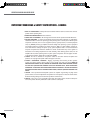
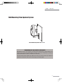
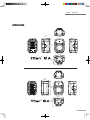
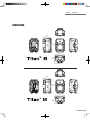
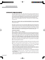
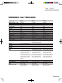
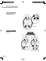
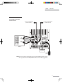
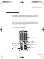
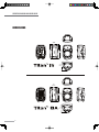
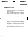
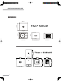
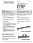
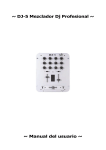
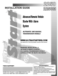
PROFESSIONAL SOUND SYSTEMS Series OPERATING MANUAL AND USER GUIDE Titan™ 8 Passive Titan™ 12 Passive Titan™ 15 Passive Titan™ 8 Active Titan™ 12 Active Titan™ 15 Active Titan™ Sub A12 Titan™ Sub A15 www.wharfedalepro.com OPERATING MANUAL AND USER GUIDE IMPORTANT WARNINGS & SAFETY INSTRUCTIONS - GENERAL 1. READ ALL INSTRUCTIONS carefully and become familiar with the features and functions of these products before operating them. 2. RETAIN THESE INSTRUCTIONS for future reference. 3. COMPLY WITH ALL WARNINGS – All warnings and instructions for this product should be adhered to. 4. USE WITH AMPLIFIERS – In order to avoid damage to drivers and other equipment, it is advisable to establish and follow a routine for powering up and powering down a sound system. With all system components connected, turn on source equipment (mixers, signal processors, record and playback units, etc.) BEFORE powering up amplifiers. Transient voltages from powering up source equipment can damage speakers if amplifiers are already turned on. Make sure that amplifier volumes are set to their minimum settings and power up any system amplifiers LAST. It is recommended that all system components be allowed to stabilize for several seconds before any source signals are introduced or level setting adjustments are made. Similarly, when shutting systems down, turn all amplifiers off first, before powering down any other system components. This also applies to active or self-powered speakers, Switch them on LAST and off FIRST. 5. CABLES – Do not use shielded or microphone cables for connection between amplifiers and speakers. Use only approved speaker cables with proper connectors. 6. RIGGING – SUSPENDING – MOUNTING – Rigging, suspending and mounting of these speaker systems can expose members of the public to serious health risks and even death. UNDER NO CIRCUMSTANCES ATTEMPT TO RIG, SUSPEND OR OTHERWISE MOUNT THESE SPEAKERS UNLESS YOU ARE FULLY QUALIFIED AND CERTIFIED TO DO SO BY RELEVANT LOCAL, STATE AND NATIONAL AUTHORITIES. ALL RELEVANT SAFETY REGULATIONS MUST BE FOLLOWED. IF YOU ARE NOT PROPERLY QUALIFIED OR DO NOT KNOW OF PERTINENT REGULATIONS, CONSULT QUALIFIED PERSONNEL FOR ADVICE. 7. CAUTION – These professional loudspeaker systems are capable of generating very high sound pressure levels. Use care with placement and operation to avoid exposure to excessive volume levels. Permanent hearing damage can result when operated to extreme levels. 8. SERVICE – There are no user serviceable parts inside this product. Users should not attempt to service this product. Warranty nullification could result if this is attempted. 1 TitanTM Series Wall Mounting Titan Speaker System WPB-1 Wall Mounting Bracket (Titan™ 12 / 15) WHARFEDALE PRO LIMITED WARRANTY Wharfedale Pro Titan™ Series speakers are warranted of manufacturing or material defects for a period of one year from the original date of purchase. In the event of malfunction, contact your authorized Wharfedale Pro dealer or distributor for information. *Be aware that warranty details may differ from country to country. Contact your dealers or distributor for information. These terms do not infringe your statutory rights. 30 OPERATING MANUAL AND USER GUIDE TABLE OF CONTENTS 1……………………………..Important Warnings & Safety Instructions 2……………………………..Important Safety Information Powered Products 4……………………………..What about the Titan™ Series? 5……………………….…….Introduction/Overview 6……………………….…….Features 7……………………………..Setting up/ Speaker Placement 7……………….…………….Connections/ Wiring - Passive 8……………….…………….Rear Panel Layout - Passive 8……………….…………….Connection Diagram Passive 12……………….…………….Rear Panel Layout - Active 15…………..……………..….Connection Diagram Active 16…………..……………..….Rear Panel Layout - Sub A12 17……………….…………….Connection Diagram Sub A12 19……………….…………….Rear Panel Layout - Sub A15 20……………….…………….Connection Diagram Sub A15 22……………………….…….Specifications - Titan™ Passive 23……………………….…….Specifications - Titan™ Active 25……………………….…….Specifications - Titan™ Subwoofers 26……………………………..Dimensional Drawings - Titan™ 8/ 12 27…………..…………………Dimensional Drawings - Titan™ 15/ 8A 28…………..…………………Dimensional Drawings - Titan™ 12A / 15A 29…………..…………………Dimensional Drawings - Titan™ Sub A12/A15 30…………………………..…Wall Mounting Titan Speaker System 30…………………………..…Warranty 3 TitanTM Series DIMENSIONS 12.28" 312mm 21.88" 556mm O MIX -- _ OPTIMIZER BR O ) (BALANCED) AA INPUT O (BALANCED) OUTPUT 15.11" 384mm 12.28" 312mm 7.1" 180mm 15.83” 402mm 27.87” 708mm 18.81” 478mm 15.83” 402mm 28 OPERATING MANUAL AND USER GUIDE TITAN™ SERIES OVERVIEW The Titan™ Series are powerful, accurate, high quality loudspeaker systems with low distortion that were designed to deliver high quality sound for the best value. From the Titan™ 8 (passive) to the Titan™ 15 Active models plus two powered subs, you have what it takes to assemble the system that your music deserves. An important factor in loudspeakers is the smoothness of the sound coverage. Many speakers that may sound acceptable in the horizontal plane have problems in the vertical plane. Due to an integral high frequency Elliptical Wave Guide (EWG), the Titan™ speakers exhibit very smooth and well behaved sound dispersion characteristics in both the horizontal and vertical planes making positioning and set-up less critical. Everyone in the room will hear the same quality sound. The Titan™ Active Series has many features to allow you greater flexibility in your sound: “BRO™ ” Bass Response Optimizer circuit, when engaged, allows for enhanced low frequency response at lower volume levels. This is very similar to a loudness switch on your home stereo amplifier. Starting with the Titan™ 12 Active speaker, two-band EQ (equalization) is added. These tone controls provide +/-10dB in each frequency range. Sometimes, in live performance, it is not easy to know if your speakers are working or not; they may be ahead of you when performing or they are not so close to you. To remedy this problem, there is a POWER ‘ON’ indicator LED on the back panel as well as in the throat of the horn to give you a visual indication that there is power to the speaker. There is also a LIMIT indicator LED on the back panel. The LIMIT LED illuminates when the signal limiter is actively limiting the level of the signal to prevent distortion and overload. The Titan™ Series rugged cabinet features moulded in handles, feet, cord wrap and cable anchors moulded into the lightweight Polypropylene cabinet. It also accommodates a bottom mounted OmniMount® 60.0 bracket for wall mounting. To make installation easier and safe, mounting and hanging brackets are available. The diagrams at the end of this manual have rigging / hanging suggestions to get the most out of your system. 5 TitanTM Series DIMENSIONS 8.7” 221mm 15.59" 396mm 2 10.47” 266mm 8.7” 221mm 12.28” 312mm 21.89” 556mm 2 15.11” 384mm 12.28” 312mm 26 OPERATING MANUAL AND USER GUIDE SETTING UP/ SPEAKER PLACEMENT The uniform dispersion of the Titan™ Series makes it easy to place the speakers where you need them, rather than trying to rearrange the room to accommodate the sound system. For the best coverage and highest quality sound, the speakers should be located above head level. Mounting hardware (M6/M8) and an integral tripod stand socket make installation easy and safe. The Titan™ Series accommodates a bottom mounted OmniMount® 60.0 (Titan™ 12, 15) and OmniMount® 30.0 (Titan™ 8) bracket and has optional rigging / hanging brackets. Before turning on the Titan™ Series, or any powered loudspeaker, be sure that the power switch is in the off position, volume controls are all the way down (at 0 level) and all audio connections are made. After power-up, speak into your mic or start the CD or MP3 player or other line level device and slowly increase the volume to the desired level. Always remember that a speaker will do what you tell it to do (i.e. deliver sound to the audience), but if the audience is too large and your system too small, you will not achieve the desired sound level without a lot of distortion. Avoid distortion as it can damage your speakers in the long term. If you cannot achieve the desired SPL, you must add more speakers or a subwoofer to the system. CONNECTIONS/ WIRING Titan™ 8 / Titan™ 12 / Titan™ 15 Passive Connecting the Titan™ Series to your system is easy. The rear panels include NL4 and 1/4” phone connectors in parallel. Run your speaker wires from your amplifier to the speaker. You can use either input connector. Use the correct gauge of speaker cable according to the power handling ability of your Titan™ Series cabinet. Use stranded insulated cable for speaker runs. It is always advisable to use heavier gauge (lower number) cables on longer runs. Be sure to connect your speakers in proper polarity (what many refer to erroneously, as phase). This means that in normal operation; connect one end of the same wire to the Red terminal on the amplifier and the other end to the + (tip) connector on the speaker. Black is always the ground or common. Although the location of the speakers is not often critical to your sound, there are some guidelines to follow, especially with powered speakers, to make the sound the best it can be. • Try to plug the amplifiers (a/k/a powered speakers) into a circuit that does not have light dimmers or refrigerators on it. When these devices are in the circuit , it is almost certain you will get a 50Hz hum in your system that cannot be removed with a EQ. • Make sure the speakers are above head level to make the projection of the sound as good as it can be. Keep the speakers out of the corner of the room. Place them away from boundaries and the microphones. Do not place them too far apart. • When using the hanging bracket or another apparatus, use a cable safety line attached to the speaker and a solid part of the wall - not the bracket. If the bracket fails, the speaker will not fall down. • If the speakers will be hanging above the audience, it often is a good idea to turn the speakers upside down and aim the horn 2/3 of the way back in the room.This will provide good coverage of the audience. 7 TitanTM Series SPECIFICATIONS - Titan™ ACTIVE (Con't) Titan™ 8 ACTIVE Titan™ 12 ACTIVE Titan™ 15 ACTIVE Switchable balanced mic or line Switchable balanced mic or line Switchable balanced mic or line level input level input level input Mic: -36dBu (-38.2dBv or Mic: -36dBu (-38.2dBv or Mic: -36dBu (-38.2dBv or 12.28mVrms) 12.28mVrms) 12.28mVrms) Inputs Input A – type Input Sensitivity Line: +4dBu (1.78dBv or 1.228Vrms) Line: +4dBu (1.78dBv or Line: +4dBu (1.78dBv or 1.228Vrms) 1.228Vrms) Maximum Input Level +22dBu +22dBu +22dBu Input Connector XLR - 1/4” Combo jack XLR - 1/4” Combo jack XLR - 1/4” Combo jack Input Impedance Balanced: 20k ohms Balanced: 20k ohms Unbalanced: Balanced: 20k ohms Unbalanced: Maximum Input Level +22dBu 10k ohms 10k ohms +22dBu +22dBu Line level input Line level input XLR - 1/4” Combo jack: 1.78dBv XLR - 1/4” Combo jack: 1.78dBv or 1.228Vrms or 1.228Vrms RCA: 0dBu (-2.2dBv or RCA: 0dBu (-2.2dBv or 0.775Vrms) 0.775Vrms) Maximum Input Level +22dBu +22dBu Input Connectors Combo jack: 1/4" - XLR / Summed Combo jack: 1/4" - XLR / Input B – type Input Sensitivity dual RCA jacks Summed dual RCA jacks Switchable LOOP / MIX Balanced Switchable LOOP / MIX Balanced Male XLR Male XLR Line Output Line Output Connector Balanced: 1k ohm Impedance: Unbalanced: Balanced: 1k ohm Unbalanced: 500 ohm 500 ohm +4dBu (1.78dBv or 1.228Vrms) +4dBu (1.78dBv or 1.228Vrms) High Efficiency Switching Mode High Efficiency Switching Mode High Efficiency Switching Mode Power Supply Power Supply Power Supply AC100~120V / 220~240V, 50 / AC100~120V / 220~240V, 50 / AC100~120V / 220~240V, 50 / 60Hz 60Hz 60Hz Power On Indicator LED LED LED Rigging / Bracket / Mounting 8 M6 threaded inserts including 4 10 M8 threaded inserts including 10 M8 threaded inserts including Options M6 threaded 4 M8 threaded 4 M8 threaded inserts on bottom in OmniMount inserts on bottom in OmniMount inserts on bottom in OmniMount 30.0-type footprint 60.0-type footprint 60.0-type footprint Pole-mount receptacle with lock Pole-mount receptacle with lock Pole-mount receptacle with lock screw screw screw 1 carry handles ( on each side) 2 carry handles (one on each 2 carry handles (one on each side) side) Optional wall-mount bracket Optional wall-mount bracket Optional wall-mount bracket Enclosure Material Injection Moulded Polypropylene Injection Moulded Polypropylene Injection Moulded Polypropylene Colours Grey or white or black Grey or white or black Grey or white or black Dimensions H x W x D (mm) 396 x 266 x 221 556 x 384 x 312 708.3 x 477.8 x 401.8 Dimensions H x W x D (in) 15.6 x 10.5 x 8.7 21.9 x 15.1 x 12.3 27.9" x 18.8" x 15.8 Net Weight (kg / lbs) 5.7kg / 12.54lbs 12.8kg / 28.16lbs 23.94kg / 52.67lbs Gross Weight (kg / lbs) 7.70kg /16.94lbs 14.8kg / 32.56lbs 26.94kg / 59.27lbs Sensitivity AC Power details Power Supply AC Power Options 24 OPERATING MANUAL AND USER GUIDE CONNECTION DIAGRAM # 2 Titan™ 8/12/15 MONO SYSTEM WITH TWO MONITORS CONNECTING MULTIPLE Titan™ 8/12/15 SPEAKERS TOGETHER IN A MONO-MAIN AND STAGE MONITOR CONFIGURATION USING A SINGLE, DUAL CHANNEL AMPLIFIER MAIN SPEAKERS STAGE MONITORS 4 OHM LOAD 4 OHM LOAD Left Right OUTPUT OF STEREO POWER AMPLIFIER OR POWERED MIXER NOTE7KLVFRQ¿JXUDWLRQUHSUHVHQWVDRKPORDGWRHDFKRXWSXWFKDQQHORIWKHDPSOL¿HU 9 TitanTM Series SPECIFICATIONS - Titan™ PASSIVE SERIES Titan™ 8 Titan™ 12 Titan™ 15 Loudspeaker Type: 8" 2-way 12" 2-way 15" 2-way Frequency Response (+/–3dB): 70 - 20kHz 55 - 20kHz 50 - 20kHz Sensitivity (1W@1M): 96dB 98dB 97dB Peak SPL: 124dB 128dB 129dB HF Coverage (H x V): Ý[Ý Ý[Ý Ý[Ý System Impedance: 8 ohm 8 ohm 8 ohm Continuous: 150W 250W 400W Music: 300W 500 800W Peak: 600W 1000 1600W Size: 203mm/ 8" 305mm/ 12" 381mm/ 15" Coil Size: 38.86mm / 1.53" 64.26mm / 2.5" 75mm / 3.0" HF DRIVER/ HORN Compression Driver Compression Driver Compression Driver Coil Size: 25mm/1" 44mm/1.75" 51mm/ 2.0" Exit Size: 30mm/1.2" 25mm/1" 25mm/1" Diaphragm Material: Cloth Titanium Titanium HF Driver Protection: Bulb DTF™ Dynamic Thermal Filament DTF™ Dynamic Thermal Filament Long-Throw EQ Compensation: N/A POWER (WATTS) LF DRIVER 3dB boost (long-throw) / Flat N/A (near-field) EWG™ - Elliptical Waveguide Horn Type: EWG™ - Elliptical Waveguide Throat Size: 25mm/1" 25mm/1" 25mm/1" 2-way 2.4KHz / Linkwitz-Riley 2-way 2.2KHz / Linkwitz-Riley 2-way 1.8KHz / Linkwitz-Riley Shape/ Material: Trapezoidal/ Polypropylene Trapezoidal/ Polypropylene Trapezoidal/ Polypropylene Rigging: (8) M6 threaded rigging points (10) M8 threaded rigging points (10) M8 threaded rigging points + (4) M8 threaded rigging points + (4) M8 threaded rigging points on bottom in Omnimount® on bottom in Omnimount® CROSSOVER Type/Frequency/Filter: ENCLOSURE + (4) M6 threaded rigging points on bottom in Omnimount® 30.0-type footprint + Speaker pole- 60.0-type footprint + Speaker mount receptacle with lock screw pole-mount receptacle with lock + 1 built-in carry handle + Optional screw + Optional wall-mount 60.0-type footprint + Speaker pole-mount receptacle with lock screw + Optional wall-mount wall-mount bracket + Optional bracket + Optional dual-unit bracket + Optional dual unit dual-unit array speaker stand array speaker stand hardware array speaker stand hardware hardware COLOURS Grey or Black or White Grey or Black or White Grey or Black or White OUTPUT CONNECTORS 2 x 1/4" jacks + 2 x NL4 2 x 1/4" jacks + 2 x NL4 2 x 1/4" jacks + 2 x NL4 Weight: 5.5kg / 12.1lbs 12kg / 26.4lbs 22kg / 48.4lbs Dimensions (H x W x D): 396 x 266 x 221mm/ 556 x 384 x 312mm/ 708.3 x 477.8 x 401.77mm/ 15.59" x 10.47" x 8.7" 21.88" x 15.1" x 12.3" 27.9" x 18.8" x 15.8 DIMENSIONS/WEIGHTS 22 OPERATING MANUAL AND USER GUIDE CONNECTION DIAGRAM # 4 USING THE Titan™ 8/12/15 WITH A PASSIVE SUBWOOFER TITAN™ 8/12/15 INPUT AMPLIFIER OUTPUTS INPUT: +1 Positive -1 Negative OUTPUT A OUTPUT B PARALLEL INPUTS WWW.WHARFEDALEPRO.COM Hi-Pass Output to PASSIVE SUBWOOFER INPUT Titan ™ 8/12/15 PASSIVE SUBWOOFER HI-PASS OUTPUT PARALLEL INP U TS H I-P A S S O U T P U T (T O MID / HI S P E AKE R ) CONNECTION DIAGRAM # 5 USING THE Titan™ 8/12/15 IN A BI-AMP SYSTEM MIXER OUTPUT ELECTRONIC CROSSOVER Low Frequ ency Crossover Outp ut High Frequency Crossover Outp ut Low Frequency Amp lifier Input High Frequ ency Amplifier Input OUTPUT A OUTPUT B Low Frequen cy Amplifier Output Subwoofer OUTPUT A OUTPUT B High Frequency Amplifier Ou tput Titan™ 8/12/15 INPUT: +1 Positive -1 Negative PARALLEL INPUTS P AR A LL E L INP U T S H I-P A S S O U T P U T (T O M ID / HI S P E AKE R) WWW.WHARFEDALEPRO.COM 11 TitanTM Series CONNECTION DIAGRAM # 1 TWO CHANNEL SYSTEM WITH HIGHPASS OUTPUT TO LEFT ACTIVE SPEAKER OR AMPLIFIER INPUT TO RIGHT ACTIVE SPEAKER OR AMPLIFIER INPUT INPUT OUTPUT (B A L A N C E D ) (B A L A N C E D ) 0 I I I I I I A I I I Left Output Right Output WWW.WHARFEDALEPRO.COM I +6 8 _ VOLUME THRU / HIGHPASS switch in “HIGHPASS” (down) mode CAUTION SPEAKER LEVEL IN THRU 0° (100Hz) HIGHPASS 180° R ISK O F ELEC TRIC SHO CK D O NO T O PEN ! WARNING: SHOCK HAZARD DO NOT OPEN AVIS: RISQUE DE CHOC ELECTRIQUE -NE PAS OUVRIR PHASE LIMIT N 2082 B ON (B A L A N CE D ) (B A L A N CE D ) INPUT OUTPUT OFF POWER AC 220-240V~50Hz 400W FUSE T4AL250V MIXER SERIALNUMBER POWER 6ZLWFKLQ³21´ XSPRGH POWER CORD NOTE: This same connection configuration can be used with OUTPUT A and B used in a full-range mode when the THRU/HIGHPASS switch is in the "THRU" (up) position. 20 OPERATING MANUAL AND USER GUIDE Titan™ 12/15 ACTIVE REAR PANEL LAYOUT HHDW Sink 2 HI / LOW EQ (HTXDOizDWion conWUoOs 4 VOLUME conWUoO A&B O O MA X 6 0 MA X +10dB -1 0 d B RCA INPUT L & R (LHIW DQG RiJhW HIG H MIC / LINE swiWch -1 0 d B G A IN POWER ON / OFF swiWch 5 ON ³BRO™” ciUcXiW swiWch 7 LO O P OUTPUT soXUFH LOOP / MIX swiWch 9 POWER connHcWoU 11 XLR OUTPUT connHcWoU 12 +10dB MI X XLR / ¼" combo jDcks IoU INPUT A&B A 13 3 LOW CD/TAPE 10 POWER ON LED inGicDWoU DQG LIMIT LED inGicDWoU 0 OFF 8 1 (BALANCED) (BALAN CED) INPUT OUTPUT TitanTM Series Titan™ Sub-A12 CONNECTION DIAGRAM # 2 USING TWO Titan™ Sub-A12 WITH TWO POWER SPEAKERS 120Hz 150Hz 100Hz 180Hz 200Hz 80Hz 0 180 M A X LOW PASS FILTER L (B A L /U N B A L (B A L A N C E D INPUT OUTPUT R AC220 240V 50Hz 250W FUSE T3.15AL250V 120Hz 150Hz 100Hz 180Hz 200Hz 80Hz 0 180 M A X LOW PASS FILTER L (B A L /U N B A L (B A L A N C E D INPUT OUTPUT R AC220 240V 50Hz 250W FUSE T3.15AL250V 18 OPERATING MANUAL AND USER GUIDE Titan™12A / 15A CONNECTION DIAGRAM # 1 Basic microphone / playback hookup MP3 Player 0 HI 0 0 ON - +6 VOLUME - MA X O FF LIM IT +6MA X -12dB -10dB VOLUME +12dB +10dB LOW POWER 0 L OFF HIGH ON B AS S RES PO N SE INPUT LOW -12dB -10dB +12dB +10dB R GAIN OPTIMIZER Place switch down in “MIX” position EQ AC INPUT CD/TAPE MI X LOO P AC Power Cord (BALANCED) A AC220-240V~60Hz AC220-240V~50Hz 400W FUSE T4AL 250V (BALANCED) B INPUT INPUT INPUT OUTPUT Microphone Connect to power outlet Titan™12A / 15A CONNECTION DIAGRAM # 2 Connecting two Titan™ 12 ACTIVE speakers together ,QSXWIURPDPLFURSKRQHRU WKHRXWSXWRIDPL[HU %HDZDUHRI0,&/,1(VZLWFKVHWWLQJ 0 HI 0 0 ON - MAX - VOLUME MAX VOLUME OFF LIMIT +10dB -10dB LOW POWER 0 L BASS RESPONSE INPUT LOW -12 dB -10d B GAIN ON OFF HIGH R +12d +10dB OPTIMIZ ER Place switch down in “MIX” position EQ AC INPUT CD/TAPE (BALANCED) A MIX LOOP (BALANCED) B INPUT INPUT 0 AC220-240V~60Hz AC220-240V~50Hz 400W FUSE T4AL 250V OUTPUT HI 0 0 ON - MAX +6 - VOLUME MAX +6 VOLUME OFF LIMIT -12d -10dB LOW +12d +10dB POWER 0 L ON OFF HIGH BASS RESPONSE INPUT LOW -10dB -12d R +12dB +10dB OPTIMIZER EQ AC INPUT CD/TAPE (BALANCED) A 15 INPUT OUTPUT INPUT MIX LOOP (BALANCED) B OUTPUT AC220-240V~60Hz AC220-240V~50Hz 400W FUSE T4AL 250V Place switch down in “MIX” position TitanTM Series Titan™ Sub A12 Rear Panel Features 1. HEAT SINK - Cooling fins for amplifier. Do not obstruct. 2. VOLUME CONTROL - Adjusts the volume. 3. INPUT L - Balanced line level input via a XLR/ ¼” combo connector. 4. INPUT R - Balanced line level input via a XLR/ ¼” combo connector. 5. OUTPUT R - Balanced male XLR connector provides output HIGHPASS signal. 6. OUTPUT L - Balanced male XLR connector provides output HIGHPASS signal. 7. POWER SOCKET - This is the connection for the IEC AC power connector. 8. LIMIT LED - LED indicator illuminates when the signal limiting function is activated. POWER LED - LED indicator illuminates when the unit is powered up 9. POWER SWITCH - Turns the power on and off to the subwoofer amplifier module. 10. PHASE SWITCH - Selects the polarity of the signal being sent to the subwoofer. 0° selects the signal polarity as it appears at the input. The 180° selection inverts the polarity of the signal. 11. CROSSOVER Adjustable 80Hz/100Hz/120Hz/150Hz/180Hz/200Hz. FREQUENCY CONTROL- 1 HHDW Sink 2 VOLUME CONTROL CROSSOVE R FREQUENCY CONTROL 120Hz 150Hz 100Hz 180Hz 200Hz 80Hz 0 180 MAX L (BAL/UNBA L (BALANCE D R INP U T 3 4 INPUT L INPUT R PHASE SWITCH LOW PASS FILTER OUTP U T 11 10 POWER SWITCH 9 LIMIT LED AND POWER LED 8 POWER SOCKET 7 AC220 240V 50Hz 250W FUSE T3.15AL250V OUTPUT L 6 OUTPUT R 5 16 OPERATING MANUAL AND USER GUIDE Titan™ Sub-A12 CONNECTION DIAGRAM # 1 TWO CHANNEL SYSTEM WITH HIGHAPASS OUTPUT 120 H z 150 H z 100 H z 180 H z 200 H z 80 H z 0 180 M AX LOW PASS FILTER L ( BAL/UNBA L ( BALANCE D R INPUT /HIW 2XWSXW 5LJKW 2XWSXW 17 OUTPUT AC220 240V 50Hz 250W FUSE T3.15AL250V TitanTM Series Titan™ 8/12/15 ACTIVE Rear Panel Features 1. Heat Sink: The heat sink allows for dissipation of heat built up from the amplifier via air cooling at the rear of the enclosure. 2. HI and LOW EQ (equalization) controls: These knobs control the equalization of the overall output signal providing +/- 10dB in each frequency range. 3. POWER ´ON´ indicator LED and LIMIT indicator LED: The bracketed LED to the left of the POWER switch illuminates when the power switch is in the´ON´ position. The LIMIT LED illuminates when the signal limiter is actively limiting the level of the signal to prevent distortion and overload. 4. VOLUME controls for INPUT A and INPUT B: These knobs control the volume of each input channel (Titan™ 8 VOLUME controls is MAIN) . 5. POWER ON / OFF switch: This switch: tums the power on and off. 6. RCA L / R (Left and Right) input jacks: These jacks provide for the input of a stereo signal (left and right). The signal is actively combined or “summed” providing a mono signal to the amplifier. 7. “BRO™” Bass Response Optimizer circuit switch: The BRO™ circuit, when engaged, allows for enhanced low frequency response at lower volume levels. 8. GAIN selection switch: This switch selects the proper gain structure for INPUT A. If a microphone is connected to INPUT A, use the HIGH selection (up). If the signal source is anything other than a microphone (playback device, keyboard or mixer output, for instance) use the LOW selection (down) . 9. Output source “LOOP / MIX” switch: In the “LOOP” mode, this switch routes the signal of INPUT B to the line level XLR OUTPUT jack, bypassing the EQ section and volume control. When in the MIX mode, this switch routes the combined (or “mixed”) signals of both INPUT A and INPUT B to the line level XLR OUTPUT jack. 10. XLR / ¼” COMBO input jacks for INPUT A and INPUT B: These convenient jacks provide for either XLR or ¼” balanced input connections to INPUT A and INPUT B (Titan™ 8 XLR ¼” COMBO input jacks for INPUT ). 11. POWER cord jack: This is a jack for a standard IEC, three prong, grounded AC electrical connection cord. Be sure that you are plugging into the correct source voltage that matches what is indicated just below the power cord jack. 12. XLR line level OUTPUT jack: This jack provides a balanced line level output of INPUT A and INPUT B signals (in MIX mode) or INPUT B signal only (in LOOP mode) for connection to additional Titan™ 12 / 15 ACTIVES, powered subwoofers or amplifiers. 14 OPERATING MANUAL AND USER GUIDE Titan™ Sub-A15 - REAR PANEL FEATURES 1. INPUT A - Balanced line level input via a XLR / ¼” combo connection. 2. OUTPUT A - Balanced male XLR connection provides output “THRU” or HIGHPASS signal (depending on switch setting). 3. SPEAKER LEVEL INPUT - Allows for connection of the output of an external amplifier to use the Titan™ Sub-A15 as a passivesubwoofer. NOTE: Disconnect the power cord when using the Titan™ Sub-A15 in this mode. 4. INPUT B - Balanced line level input via a XLR / ¼” combo connection. 5. OUTPUT B - Balanced male XLR connection provides output “THRU” or HIGHPASS signal nding on switch setting). 6. HEATSINK - Cooling fins for amplifier. Do not obstruct. 7. VOLUME CONTROL - Adjusts volume level of the subwoofer. 8. THRU / HIGHPASS SWITCH - Selects the signal type that is routed to the OUTPUT jacks. “THRU” sends the unprocessed signal to the outputs. “HIGHPASS” filters the signal and only sends signals above 100Hz to the outputs. 9. PHASE SWITCH - Selects the polarity of the singal being sent to the subwoofer. 0° selects the signal polarity as it appears at the input. The “180°” selection inverts the phase of the signal. 10. LIMIT LED - LED indicator illuminates when the singal limiting function is activated. 11. POWER LED - LED indicator illuminates when the unit is powered up. 12. POWER SOCKET - This is the connection for the IEC AC power connector. 13. POWER SWITCH - Turns the power on and off to the subwoofer amplifier module. 2 3 OUTPUT A INPUT OUTPUT (B A L A N C E D ) (B A L A N C E D ) I 0 I I 4 I WWW.WHARFEDALEPRO.COM IMAX 8 _ VOLUME CAUTION SPEAKER LEVEL INPUT RISK THRU SPEAKER LEVEL IN (100Hz) HIGHPASS 0° 180° PHASE O F ELECTR IC SHO CK D O N O T O PE N ! WARNING: SHOCK HAZARD DO NOT OPEN AVIS: RISQUE DE CHOC ELECTRIQUE -NE PAS OUVRIR LIMIT N 2082 INPUT B B 5 OUTPUT B ON (B A L A N C ED ) (B A L A N C ED ) INPUT OUTPUT OFF POWER SERIALNUMBER 19 7 I I A VOLUME CONTROL I I INPUT A 6 I 1 HEATSINK THRU/HIGHPASS SWITCH PHASE SWITCH LIMIT LED 8 9 POWER LED 10 11 POWER SOCKET 12 POWER SWITCH 13 AC 220-240V~50Hz 400W FUSE T4AL250V TitanTM Series Titan™ 8 / Titan™ 12 / Titan™ 15 ACTIVE Connecting the Titan™ Active Series to your system is just as easy, with a couple more things to do. Plug in the electrical cable and your audio cables and switch the unit on. Always be sure there is a good electrical ground. The Titan™ Series rear panel has one combo XLR / TRS Jack input. Be sure to use high quality shielded cable and high quality connectors. The volume control is conveniently located above the input sensitivity switch (mic/line). Be sure you have that switch in the correct position. The Loop / Mix Switch - Titan™ 12A / 15A ONLY The LOOP/MIX switch allows you to control the signal content going to the XLR OUTPUT jack. In the “LOOP” mode, this switch routes the signal of INPUT B to the line level XLR OUTPUT jack, bypassing the EQ section and volume control. When in the MIX mode, this switch routes the combined (or “mixed”) signals of both INPUT A and INPUT B to the line level XLR OUTPUT jack. This signal can then be sent to additional powered speakers or powered subwoofers. Titan™ 8 ACTIVE - REAR PANEL FEATURES HHDW Sink 4 VOLUME conWUoOs POWER ON LED iQGicDWoU DQG LIMIT LED iQGicDWoU POWER ON/OFF swiWch 8 1 3 5 MIC/ LINE swiWch XLR oU 1/4” 10 combo jDcksIoU INPUT POWER cRQQHcWoU 11 12 OPERATING MANUAL AND USER GUIDE CONNECTION DIAGRAM # 2 USING TWO Titan™ Sub-A15's WITH TWO POWERED SPEAKERS TO LEFT MAIN POWERED SPEAKER INPUT OUTPUT (B A L AN C E D ) (B A L AN C E D ) 0 I I I I FROM MIXER OUTPUT LEFT I I A I I I WWW.WHARFEDALEPRO.COM I MAX 8 _ VOLUME CAUTION THRU SPEAKER LEVEL IN RISK O F ELECTRIC SHO C K D O N O T O PE N 0° 180° (100Hz) HIGHPASS ! POWER CORD WARNING: SHOCK HAZARD DO NOT OPEN AVIS: RISQUE DE CHOC ELECTRIQUE -NE PAS OUVRIR PHASE TO INPUT OF 2nd SUBWOOFER N 2082 B ON (B A L A N C ED ) (B A L AN C E D ) INPUT OUTPUT POWER CORD OFF POWER AC 220-240V~50Hz 400W FUSE T4AL250V RIGHT SIDE SUBWOOFER SERIALNUMBER LEFT SIDE SUBWOOFER INPUT OUTPUT (B A L AN C E D ) (B A L AN C E D ) I I I A I I I WWW.WHARFEDALEPRO.COM IMAX 8 _ VOLUME CAUTION SPEAKER LEVEL IN TO RIGHT MAIN POWERED SPEAKER 0 I I I FROM MIXER OUTPUT RIGHT THRU 0° (100Hz) HIGHPASS 180° RISK O F ELECTRIC SHO C K D O N O T O PE N PHASE LIMIT N 2082 POWER CORD B ON (B A L A N C ED ) (B A L AN C E D ) INPUT OUTPUT OFF POWER POWER CORD SERIALNUMBER 21 ! WARNING: SHOCK HAZARD DO NOT OPEN AVIS: RISQUE DE CHOC ELECTRIQUE -NE PAS OUVRIR AC 220-240V~50Hz 400W FUSE T4AL250V TitanTM Series CONNECTION DIAGRAM # 3 Titan™ 8/12/15 MONO MAIN SYSTEM WITH TWO MONITORS (another view) MAIN SPEAKER #1 PARALLEL CONNECTION TO SECOND MAIN SPEAKER INPUT: +1 Positive -1 Negative MAIN SPEAKER #2 INPUT: +1 Positive -1 Negative OR PARALLEL INPUTS PARALLEL INPUTS WWW.WHARFEDALEPRO.COM WWW.WHARFEDALEPRO.COM (CHANNEL 1) FROM MIXER MAIN OUT TWO CHANNEL AMPLIFIER OUTPUTS FROM MIXER MONI TOR OU T MODEL S-SERIES Professional Power Amplifier = NL4 Connection WWW.WHARFEDALEPRO.COM = ¼” Connection AMPLIFIER INPUTS (CHANNEL 2) MONITOR SPEAKER #1 INPUT: +1 Positive -1 Negative PARALLEL INPUTS WWW.WHARFEDALEPRO.COM PARALLEL CONNECTION TO SECOND MONITOR SPEAKER OR MONITOR SPEAKER #2 INPUT: +1 Positive -1 Negative PARALLEL INPUTS WWW.WHARFEDALEPRO.COM NOTE7KLVFRQ¿JXUDWLRQUHSUHVHQWVDRKPORDGWRHDFKRXWSXWFKDQQHORIWKH DPSOL¿HU 10 OPERATING MANUAL AND USER GUIDE SPECIFICATIONS - Titan™ ACTIVE SERIES Titan™ 8 ACTIVE Titan™ 12 ACTIVE Titan™ 15 ACTIVE System Type Active 8” 2-way Bi-Amplified Active 12” 2-way Bi-Amplified Active 15” 2-way Bi-Amplified Frequency Response (+/-3dB) 70-20kHz 55-20kHz 50-20kHz Low Frequency Driver (mm/in.) 205mm / 8” 305mm / 12” 381mm / 15” High Frequency Driver Compression Driver Titanium Compression Driver Titanium Compression Driver Exit Size (mm / inches) 30mm / 1.2" 25mm / 1" 25mm / 1" Dispersion (H x V) 90° x 60° 90° x 60° 90° x 60° Impedance (ohms) Low Frequency (Class D) Rated 150W RMS, 300W Peak Rated 250W RMS, 500W Peak Rated 350W RMS, 700W Peak High Frequency (Class A/B) Rated 30W RMS, 60W Peak Rated 50W RMS, 100W Peak Rated 70W RMS, 140W Peak Electronic Crossover: 24dB/octave Linkwitz-Riley 24dB/octave Linkwitz-Riley 24dB/octave Linkwitz-Riley Crossover Frequency 2.4kHz 2.3kHz 1.8kHz High (±10dB) 10kHz Shelving High (±10dB) 10kHz Shelving Low (±10dB) 100Hz Shelving Low (±10dB) 100Hz Shelving +5dB at 60Hz +5dB at 60Hz 30Hz, Second-order filter 30Hz, Second-order filter 30Hz, Second-order filter Power On Power switch on / off mute Power switch on / off mute Power switch on / off mute Thermal Amplifier shutdown, auto reset Amplifier shutdown, auto reset Amplifier shutdown, auto reset Low Line Voltage Shut Down 60% Nominal line voltage 60% Nominal line voltage 60% Nominal line voltage Driver Protection Independent LF and HF limiters Independent LF and HF limiters Independent LF and HF limiters DC Protection Yes Yes Yes Short Protection Yes Yes Yes Clip Limiter: Turns on approx 150W output Turns on approx 250W output Turns on approx 350W output Limiter Indicator Red LED Red LED Red LED Power Indicator Blue LED Blue LED Blue LED Amplifiers Equalization: Bass Response Optimizer (BRO™) circuit Subsonic Filter Amplifier Protection 23 TitanTM Series TM Titan™ REAR PANEL LAYOUT INPUT: +1 Positive -1 Negative INPUT: +1 Positive -1Negative PARALLELINPUTS : POWER HANDLING POWER HANDLING: 150 W atts C ontinuous 300 W atts Program 500 W atts Peak Im pedance: 8 O hm s 200 Watts Continuous 500 Watts Program 1000 Watts Peak Impedance: 8 Ohms WWW.WHARFEDALEPRO.COM WWW.WHARFEDALEPRO.COM CONNECTION DIAGRAM #1 Titan™ 8/12/15 TWO - CHANNEL SOUND SYSTEM CONNECTION RIGHT SPEAKER MICROPHONES NL4 MIXER OUTPUTS INPUT: +1 Positive -1 Negative PARALLEL INPUTS MIXER MODELS-SERIES AMP INPUTS ProfessionalPowerAmplifier WWW.WHARFEDALEPRO.COM AMPLIFIER OUTPUTS NL4 INPUT: +1 Positive -1 Negative PARALLEL INPUTS LEFT SPEAKER 8 OPERATING MANUAL AND USER GUIDE SPECIFICATIONS - Titan™ SUB SERIES TITAN™ Sub-A15 Titan™ Sub-A12 System Type Band-pass subwoofer Reflex subwoofer Frequency Response (+/-3dB) 45-150Hz 55-200Hz Enclosure Material 18mm Plywood 15mm MDF Enclosure Colour Grey or Black Grey or Black Frame material Die-cast aluminium frame steel frame Size (mm / inches) 404mm / 15” 305mm / 12” Coil Size (mm / inches) 75 / 3” 64.26mm / 2.5” Impedance 4 ohm 4 ohm Speaker Pole Adapter Yes Yes Inputs A & B - Type / Connection Balanced Line Level inputs via two Balanced Line Level inputs via combo connectors two combo connectors Balanced Line Level inputs via two Balanced Line Level inputs via combo connectors two combo connectors Input Sensitivity 0.775V 0.37V High Pass Frequency Selection 100Hz 150Hz Phase Switch Selection 0° / 180° 0° / 180° Crossover Frequency (HZ) 150 80/ 100/ 120/ 150/ 180/ 200 Speaker Level Input Impedance 1/4” TS Phone input Speaker Level Input Connection Amplifier Power: Continuous 400W 250W Amplifier Power: Peak 600W 500W Power On Indicator LED LED Power On Protection Power switch on / off mute Power switch on / off mute Thermal Protection Amplifier shutdown, auto reset Amplifier shutdown, auto reset Low Line Voltage Shut Down 60% Nominal line voltage 60% Nominal line voltage Driver Protection Independent LF limiters Independent LF limiters DC Protection Yes Yes Short Protection Yes Yes Clip Limiter: Turns on approx 400W output Turns on approx 250W output Limiter Indicator Red LED Red LED Power Indicator Blue LED Blue LED Dimensions H x W x D: (mm) 630.0 x 478.0 x 640.0 360.0 x 493 x 431.0 Dimensions H x W x D (in) 24.8 x 18.8 x 25.2 14.2 x 19.4 x 16.9 Weight (Net) kg / lbs 45.48kg / 100.0lbs 22.31kg /49.0lbs Output A & B Type / Connection (adjustable) 25 TitanTM Series FEATURES ʍ 2-way reflex systems ʍ Passive (3) and Active (3) + Powered Subs (2) ʍ Low distortion, high power woofers ʍ 25.4mm Titanium high frequency compression drivers ʍ BRO™ Bass Response Optimizer (Titan™ 12/15 Active) ʍ Class D Low Frequency Amplifier (Active) ʍ Class A/B High Frequency Amplifier (Active) ʍ XLR output for connecting to another powered speaker ʍ RCA inputs for MP3, CD or other inputs ʍ Integral Elliptical Wave Guide (EWG) 90° x 60° ʍ Power On LED indicator in horn throat and back panel ʍ Active signal limiting system with LED indicator ʍ DTF™ Dynamic Thermal Filament HF driver protection (Titan™ 8,12,15 Passive) ʍ Light weight, high strength Polypropylene cabinet ʍ Integral 35mm (1-3/8”) stand socket ʍ M6, M8 hanging points ʍ NL4 & 1/4” speaker inputs (Passive) ʍ Combo XLR/ 1/4” input jacks (Active) ʍ Internal crossover passive outputs (Sub-A12/15) ʍ Accommodates OmniMount® 60.0 bracket 6 OPERATING MANUAL AND USER GUIDE DIMENSIONS 15.83” 402mm 27.87” 708mm 2 18.81” 478mm 15.83” 402mm 8.7” 221mm 15.59" 396mm 2 10.47” 266mm 8.7" 221mm 27 TitanTM Series WHAT ABOUT THE Titan™ SERIES? Wharfedale Pro Titan™ Series of passive and self-powered foreground/back-ground music and sound reinforcement speakers are designed for demanding professional applications such as reproduction and reinforcement of music and sound in venues as diverse as live performance venues, airports, houses of worship, A/V presentations, schools, retail shops, restaurants and public houses. The Titan™ Series loudspeakers are high quality speaker systems designed to provide the best sound in a compact, feature laden, easy to use package. It is designed to provide transparent and accurate sound reproduction or reinforcement. The 25mm Exit Titanium high frequency drivers project crystal clear high frequencies . A proprietary 90° x 60° Elliptical Wave Guide (EWG) delivers the high frequencies in a well defined, even coverage pattern. Dynamic passages, such as the crack of a snare drum or the report of a cannon, come through just like the real thing. The Titan™ Series are also ideal in Audio/Visual applications. The rich accurate sound is a great complement to any visual performance or presentation. Easy to transport and quick to set up, the Titan™Active Series is the ideal choice for the serious professional. Accessory wall brackets and rigging components available. INTRODUCTION Wharfedale Pro Titan™ Series loudspeakers are the result of many years of experience in the use, design and manufacturing of professional loudspeaker products. We take great pride in engineering and building every Wharfedale Pro loudspeaker and wish to thank you for entrusting us with your sound. From the time Gilbert Briggs built his first loudspeaker in 1932, to the present, Wharfedale Loudspeakers have maintained the same standard of quality in components, workmanship and performance. Actually, Wharfedale is one of a few present day manufacturers that design, engineer and build all of their own transducers. Please take a few minutes to read this manual completely in order to ensure that you get the most out of your Titan™ Series Loudspeaker system. 4 OPERATING MANUAL AND USER GUIDE DIMENSIONS 493.0 431.0 Titan SUB A12 TOP VIEW 360.0 360.0 463.0 120Hz 150Hz 100Hz 180Hz 200Hz 80Hz 0 180 MAX LOW PASS FILTER L (BAL/UNBAL) (BALANCED) INPUT OUTPUT R AC 22 0 240V 50Hz 250W FUSE T3.15 AL 250V 431.0 SIDE VIEW FRONT VIEW Titan REAR VIEW SUB A15 TOP VIEW INPUT (BALANCED) OUTPUT (BALANCED) I 0 I I I I I A I I I WWW.WHARFEDALEPRO.COM IMAX 8 _ VOLUME CAUTION THRU SPEAKER LEVEL IN (100Hz) HIGHPASS RISK OF ELECTRIC SHOCK DO NOT OPEN 0° 180° PHASE ! WARNING: SHOCK HAZARD DO NOT OPEN AVIS: RISQUE DE CHOC ELECTRIQUE -NE PAS OUVRIR LIMIT N 2082 B ON (BALANCED) (BALANCED) INPUT OUTPUT OFF POWER AC 220-240V~50Hz 400W FUSE T4AL250V SERIALNUMBER LEFT SIDE VIEW 29 FRONT VIEW RIGHT SIDE VIEW BACK VIEW TitanTM Series IMPORTANT SAFETY INFORMATION POWERED PRODUCTS Servicing is required when the apparatus has been damaged in any way, such as power supply cord or plug is damaged, liquid has been spilled or objects have fallen into the apparatus, the apparatus has been exposed to rain or moisture, does not operate normally, or has been exposed to rain or moisture, does not operate normally, or has been dropped. This symbol indicates that there are important operating and maintenance instructions in the literature accompanying this unit. Warning: To reduce the risk of fire or electrical shock, do not expose this product to rain or moisture. The product must not be exposed to dripping and splashing and no object filled with liquids such as a vase of flowers should be placed on the product. This symbol indicates that dangerous voltage constituting a risk of electric shock is present within this unit. No naked flame sources such as candles should be placed on the product. Read these instructions. Keep these instructions. Head all warnings. Follow all instructions. Do not use this apparatus near water. Clean only with dry cloth. Do not block any ventilation openings. Install in accordance with the manufacturer's instructions. Do not install near any heat sources such as radiators, heat registers, Stoves, or other apparatus(including amplifiers) that produce heat. Do not defeat the safety purpose of the polarized or grounding type plug. A polarized plug has two blades with one wider than the other. A grounding type plug has two blades and a third grounding prong. The wider blade or the third prong are provided for your safety. If the provided plug does not fit into your outlet, consult an electrician for replacement of the obsolete outlet. Protect the power cord from being walked on or pinched, particularly at Plugs, convenience receptacles, and the point where they exit from the apparatus. Use only attachments/accessories specified by the manufacturer. Unplug this apparatus during lightning storms or when unused for long periods of time. Caution: Changes or modifications not expressly approved by the manufacturer could void the user's authority to operate this device. Warning: The mains power switch for this appliance is located on the rear panel. To permit free access to this switch, the apparatus must be located in an open area without any obstructions. ESSENTIAL INFORMATION FOR UK USERS The power cord on your subwoofer may be supplied with a plug incorporating a fuse, the value of which is indicated on the pin face of the plug. Should the fuse need to be replaced, an ASTA or BSI approved BS1362 fuse must be used of the same rating. If the plug is cut off it must NOT be re-used. Dispose of any such plug safely. There is a danger of electric shock if a cut-off plug is inserted into a mains socket. The wires in the mains lead are coloured in accordance with the following code: Green and Yellow - Earth: Blue - Neutral: Brown - Live. As the colours of the wires in the mains lead may not correspond with the markings identifying the terminals in the replacement mains plug, proceed as follows: The wire coloured Blue must be connected to the terminal marked with the letter ¨N¨ or coloured Black. The wire coloured Brown must be connected to the terminal marked with the letter ¨L¨ or coloured Red. The wire coloured Green and Yellow must be connected to the terminal marked with the letter ¨E¨ , or coloured Green, or Green and Yellow, or marked with the Earth symbol. Refer all servicing to qualified service personnel. Use only with a cart, stand, tripod, bracket, or table specified by the manufacturer, or sold with the apparatus. When a cart is used, use caution when moving the cart/ apparatus combination avoid injury from tip-over. 2 Wharfedale Professional IAG HOUSE Sovereign Court, Ermine Business Park Huntingdon, Cambs, PE29 6XU, England www.wharfedalepro.com Wharfedale Professional reserves the right to alter or improve specifications without notice All rights reserved © 2008 Wharfedale Pro. Wharfedale Pro is a member of the International Audio Group (IAG). ᥦ⠜ᮍᓣ ᇕᑩ 30 28 26 24 22 20 18 16 14 12 10 8 6 4 2 ᇕ䴶 1 3 5 7 9 11 13 15 17 19 21 23 25 27 29