1
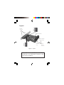
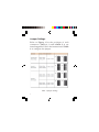
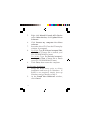
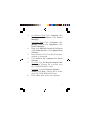
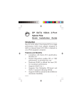
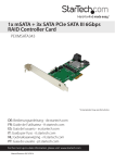
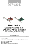
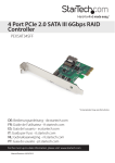
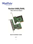
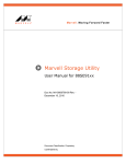
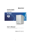
DP SATA 6Gb/s 4-Port
Hybrid PCIe
Quick
Installation
Guide
Introduction
The DP SATA 6Gb/s 4-Port Hybrid PCIe is a high
performance SATA host adapter designed to
add four internal Serial ATA 6Gb/s channels
and two eSATA external connectors to your
PCIe-equipped computer.
Features and Benefits
•
•
•
•
•
•
04-0860A
Compliant with Serial ATA specification,
Revision 3.0
Hybrid (HyperDuo) enables 80% of SSD
performance at one-third the cost
Hardware RAID to offload the host CPU
for maximum performance
Supports RAID 0, 1 & 10
Supports Port Multiplier FIS-based and
Native Command Queuing (NCQ)
Supports TRIM to extend the life of SSDs for
maximum durability
1
System Requirements
•
•
Desktop PC with an available 4-lane (or
more) PCIe slot
Windows® 8 (32-/64-bit) / 7 (32-/64-bit) /
Vista (32-/64-bit) / XP (32-/64-bit) /Server
2003 & 2008 (32/64-bit) / Server 2008 R2
Package Contents
•
•
•
•
•
2
DP SATA 6Gb/s 4-Port Hybrid PCIe
Spare low profile bracket
SATA data cable (2)
Driver CD
Quick installation guide
Layout
3 2 1
JP1
2 eSATA
JP2
JP3
JP4
connectors
eSATA 6
HDD LED (optional)
eSATA 5
SATA 3 (bottom)
& SATA 4 (top)*
SATA 1
3 2 1
(bottom)
JP5
JP6
JP7
JP8
& SATA 2
4 SATA
(top)
internal
connectors
Figure 1: Layout
*Note: The internal SATA 3 and SATA 4
connectors are dedicated channels, they
can not be disabled.
3
Jumper Settings
Refer to Figure 1 for the positions of each
connectors. SATA 1, 2 and eSATA 5, 6 are
interchangeable. Follow the instructions in Table
1 to configure the jumper.
3 2 1
3 2 1
JP5
JP1
3 2 1
3 2 1
JP1
JP5
3 2 1
3 2 1
JP5
JP1
3 2 1
JP1
Table 1: Jumper Settings
4
3 2 1
JP5
Hardware Installation
For Low profile systems, install the spare low
profile bracket now.
General instructions for installing the card are
provided below. Since the design of computer
cases and motherboards vary, refer to your
computer's reference manual for further
information, if needed.
Static Electricity Discharge may permanently
damage your system. Discharge any static
electricity build up in your body by touching your
computer case for a few seconds. Avoid any
contact with internal parts and handle cards
only by their external edges.
1.
2.
3.
4.
Turn OFF the power to your computer and
any other connected peripheral devices.
Unplug the power cord from the back of the
computer.
Remove your computer cover.
Remove the slot bracket cover from an
available PCI Express slot.
5
5.
6.
Carefully align the card's bus connector
with the selected PCI Express slot on the
motherboard. Push the board down firmly,
but gently, until it is well seated.
Replace the slot bracket holding screw to
secure the card.
Device Connection
The DP SATA 6Gb/s 4-Port Hybrid PCIe supports
up to four Serial ATA hard disk drives. You will
need to purchase additional SATA data cable(s)
if a third or forth channel is going to be used.
1.
Install your hard disk drive(s) in the chassis.
2.
Connect the Serial ATA hard disk drive to
the system power supply.
Note: For hard drives with both SATA
power connector and legacy 4-pin
connector, use either the SATA power
connector or the legacy 4-pin power
connector. Using both power connectors
may damage the hard drive.
6
3.
Connect one end of the Serial ATA cable to
the hard disk drive.
Serial ATA
Power
Figure 2: SATA hard disk drive connections
4.
5.
Attach the other end of the Serial ATA data
cable to the Serial ATA connector on the DP
SATA 6Gb/s 4-Port Hybrid PCIe.
Follow the same instructions to connect the
second hard drive, if needed. Device
connection is now complete.
RAID Arrays
This controller can be configure for hardware
RAID 0, 1 and 10, if needed. If you don't need
RAID 0, 1 or 10, please proceed to Driver
Installation on page 13. RAID Arrays are setup
in the DP SATA 6Gb/s 4-Port Hybrid PCIe BIOS.
7
RAID 0 (Striping)
This RAID array to be used on New/Blank hard
drives. Striping will destroy data on the hard
drive. A minimum of 2 drives are needed to
configure this array.
1.
2.
3.
4.
5.
8
As the BIOS boots, press Ctrl+M when
prompted to enter the RAID BIOS.
At the next screen select HBA 0: Marvell
0, press Enter. Select Configuration
Wizard, then press Enter.
Use the Up or Down arrow key to choose a
hard drive. Press the Spacebar to select the
hard drive. Perform the same procedure
with the other hard drive(s), you want to
add to the array. When you are finished
selecting the hard drives, press Enter.
Select RAID Level or HyperDuo, press
Enter. Select RAID 0, then press Enter.
Note: You can rename the VD Name. This
is optional.
Select Next, press Enter. When asked Do
you want to create this virtual disk? press
Y to select Yes.
6.
Press F10 to exit the BIOS. When asked Do
you want to exit from Marvell BIOS Setup?
press Y to exit and reboot.
RAID 1 (Mirror)
Two drives are needed to make a Mirror.
1.
2.
3.
4.
As the BIOS boots, press Ctrl+M when
prompted to enter the RAID BIOS.
At the next screen select HBA 0: Marvell 0,
press Enter. Select Configuration Wizard,
then press Enter.
Use Up or Down arrow key to choose a
hard drive. Press Spacebar to select the
hard drive. Perform the same procedure
with the other hard drive. Once both hard
drives are selected press Enter.
Select RAID Level or HyperDuo, press
Enter. Select RAID1, then press Enter.
Note: You can rename the VD Name. This
is optional.
5.
Select Next, press Enter. When asked Do
you want to create this virtual disk? press
Y to select Yes.
9
6.
Press F10 to exit the BIOS. When asked Do
you want to exit from Marvell BIOS Setup?
press Y to exit and reboot.
RAID 10 (Mirror+Striping)
Four drives are needed to make a RAID10.
1.
2.
3.
4.
As the BIOS boots, press Ctrl+M when
prompted to enter the RAID BIOS.
At the next screen select HBA 0: Marvell 0,
press Enter. Select Configuration Wizard,
then press Enter.
Use Up or Down arrow key to choose hard
drive. Press Spacebar to select the hard
drive. Perform the same procedure with
the other hard drives. Once all hard drives
are selected press Enter.
Select RAID Level or HyperDuo, press
Enter. Select RAID10, then press Enter.
Note: You can rename the VD Name. This
is optional.
5.
10
Select Next, press Enter. When asked Do
you want to create this virtual disk? press
Y to select Yes.
6.
Press F10 to exit the BIOS. When asked Do
you want to exit from Marvell BIOS Setup?
press Y to exit and reboot.
Rebuilding a Failed Mirror Set
When a failure to one member occurs, you will be
notified by the RAID BIOS during boot up. The
steps below will guide you in rebuilding a failed
mirror set.
1.
Replace the failed drive with one of equal or
greater capacity, then boot the computer.
2.
As the BIOS boots press Ctrl+M when
prompted to enter the RAID BIOS.
3.
Select New_VD, press Enter. Select Rebuild
then press Enter.
4.
Select the new hard drive under Free
Physical Disks.
5.
Press Spacebar to select hard drive, then
press Enter.
6.
When asked Do you want to rebuild with
selected physical disk on this vd?, press Y
to select Yes. The mirror will begin
rebuilding. Do not interfere with the process
until completion.
11
7.
Press F10 to exit the BIOS. When asked Do
you want to exit from Marvell BIOS setup?
press Y to exit and reboot.
Deleting RAID Arrays
Deleting a RAID array will destroy data on the
hard drives. Please backup all data on your hard
drive before deleting any RAID array.
1.
2.
3.
4.
5.
12
As the BIOS boots press Ctrl+M when
prompted to enter the RAID BIOS.
Select New_VD press Enter. Select Delete
then press Enter.
When asked Do you want to delete this
virtual disk? press Y to select Yes.
When asked Do you want to delete MBR
from this virtual disk?, press Y to select
Yes.
Press F10 to exit the BIOS. When asked Do
you want to exit from Marvell BIOS setup?
press Y to exit and reboot.
Driver Installation
This section provides information on how to
install the drivers.
Windows 8 (32-/64-bit) / Windows 7 (32-/
64-bit) / Server 2008 R2
For New Installation
1.
Setup the RAID array prior to Windows
installation. If RAID is not required, go
directly to step 2.
2.
Follow Windows installation procedure.
3.
At the Windows desktop:
For Windows 8 / 7: Right click Computer,
click Manage, click Device Manager.
For Server 2008 R2: Click Computer, click
Manage. Double click Diagnostics, click
Device Manager.
4.
Right click Marvell Console or Marvell
Console ATA Device under Other devices,
click Update Driver Software.
5.
Click Browse my computer for driver
software, insert the driver CD. Close the
CD autoplay window if prompted.
13
6.
7.
For 32-bit: Type D:\Drivers\storport\i386,
click Next. (Change D: to match your CD/DVD-ROM drive letter)
For 64-bit: Type D:\Drivers\storport\
amd64, click Next. (Change D: to match
your CD-/DVD-ROM drive letter)
Click Close, then restart the computer.
For Existing Installation
1.
Setup the RAID array prior to driver
installation and boot up to Windows. If
RAID is not required, simply boot up
Windows and go directly to step 2.
2.
For Windows 8 / 7: Right click Computer,
click Manage, click Device Manager.
For Server 2008 R2: Click Computer, click
Manage. Double click Diagnostics, click
Device Manager.
3.
Right click Marvell Console or Marvell
Console ATA Device under Other devices,
click Update Driver Software.
4.
Click Browse my computer for driver
software, insert the driver CD. Close the
CD autoplay window if prompted.
14
5.
6.
For 32-bit: Type D:\Drivers\storport\i386,
click Next. (Change D: to match your
CD-/DVD-ROM drive letter)
For 64-bit: Type D:\Drivers\storport\
amd64, click Next. (Change D: to match
your CD-/DVD-ROM drive letter)
Click Close, then restart the computer.
Windows Vista (32-/64-bit) / Server 2008
(32-/64-bit)
For A New Installation
1.
Setup the RAID array prior to Windows
installation. If RAID is not required, go
directly to step 2.
2.
Follow Windows installation procedure.
3.
After booting up the Windows, click Cancel
at the Found New Hardware window.
4.
For Windows Vista: Right click Computer,
click Manage, click Continue, click Device
Manager.
For Server 2008: Right click Computer,
click Manage. Double click Diagnostics,
click Device Manager.
15
5.
6.
7.
8.
9.
Right click Marvell Console ATA Device
under Other devices, click Update Driver
Software.
Click Browse my computer for driver
software.
Insert the driver CD. Close the CD autoplay
window if prompted.
For 32-bit: Type D:\Drivers\storport\i386,
click Next. (Change D: to match your
CD-/DVD-ROM drive letter)
For 64-bit: Type D:\Drivers\storport\
amd64, click Next. (Change D: to match
your CD-/DVD-ROM drive letter)
Click Close, then restart the computer.
For Existing Installation
1.
Setup the RAID array prior to driver
installation and boot up to Windows. If
RAID is not required, simply boot up
Windows and go directly to step 2.
2.
At the Found New Hardware window,
click Cancel.
16
3.
4.
5.
6.
7.
8.
For Windows Vista: Click Computer, click
Manage, click Continue, click Device
Manager.
For Server 2008: Click Computer, click
Manage. Double click Diagnostics, click
Device Manager.
Right click Marvell Console ATA Device
under Other devices, click Update Driver
Software.
Insert the driver CD. Close the CD autoplay
window if prompted.
Click Browse my computer for driver
software.
For 32-bit: Type D:\Drivers\storport\i386,
click Next. (Change D: to match your
CD-/DVD-ROM drive letter)
For 64-bit: Type D:\Drivers\storport\
amd64, click Next. (Change D: to match
your CD-/DVD-ROM drive letter)
Click Close, then restart the computer.
17
Windows XP (32-/64-bit) / Server 2003
(32-/64-bit)
Important: New Installation is not supported by
Windows XP and Windows Server 2003.
For Existing Installation
1.
Setup the RAID array prior to driver
installation and boot up Windows. If RAID
is not required, simply boot up Windows
and go directly to step 2.
2.
At the Found New Hardware window,
click No, not this time, click Next. Skip this
step if not prompted.
3.
Click Install from a specific location
(advanced), click Next.
4.
Check Include this location in the search,
uncheck the other box.
5.
Insert driver CD.
For 32-bit: Type D:\Drivers\miniport\i386,
click Next. (Change D: to match your
CD-/DVD-ROM drive letter)
For 64-bit: Type D:\Drivers\miniport\
amd64, click Next. (Change D: to match
your CD-/DVD-ROM drive letter)
18
6.
7.
8.
Click Finish.
Repeat steps 2-6.
Restart the computer.
To Verify Windows Installation
1.
2.
Use Device Manager to verify installation.
For Windows 8 / 7 / XP / Server 2003: Right
click Computer or My Computer, click
Manage, click Device Manager.
For Windows Vista: Right click Computer,
click Manage, click Continue. Click Device
Manager.
For Windows Server 2008 / 2008 R2: Right
click Computer, click Manage. Double click
Diagnostics, click Device Manager.
Double click System devices, Marvell
Unify Configuration should be displayed.
19
Marvell Storage Utility
Follow the instuctions below to install the Marvell
Storage Utility GUI.
1.
Double click MSUSetup in the GUI folder
on your software CD.
2.
At the User Account Control, click Yes or
Continue. Skip this step if not prompted.
3.
At Welcome to the Marvell MSU V4 Setup
Wizard, click Next.
4.
At License Agreement, select I accept the
terms of the License Agreement, click Next.
5.
Click Next again.
6.
Change the Destination folder if you want
to change it; otherwise, click Install.
7.
Click Allow access at the Windows Security
Alert. Skip this step if not prompted.
8.
At the Completing the Marvell MSU V4
Setup Wizard, click Finish.
9.
After successful installation, the MSU GUI
is ready for use. Enable the software by
double click on it.
20
10.
Type in the Username and Password to log
in. Username and Password are your
Windows user name and password. If you
have a user name but no password, please
leave the password field blank.
Figure 3
11.
After log in, you can access to the MSU user
interface for further VD management. See
Figure 4 in the next page.
Refer to your UserGuide on the software
CD for more details.
21
Figure 4
22
Technical Support and Warranty
QUESTIONS? SIIG’ s Online Support has answers! Simply visit our web site at
www.siig.com and click Support. Our online support database is updated daily with
new drivers and solutions. Answers to your questions could be just a few clicks away.
You can also submit questions online and a technical support analyst will promptly
respond.
SIIG offers a 5-year manufacturer warranty with this product. This warranty covers the
original purchaser and guarantees the product to be free of any defects in materials or
workmanship for five (5) years from the date of purchase of the product.
SIIG will, at our discretion, repair or replace (with an identical product or product
having similar features and functionality) the product if defective in materials or
workmanship. This warranty gives you specific legal rights, and you may also have other
rights which vary from state to state. Please see our web site for more warranty details.
If you encounter any problems with this product, please follow the procedures below.
A) If it is within the store's return policy period, please return the product to the store
where you purchased from.
B) If your purchase has passed the store's return policy period, please follow the steps
below to have the product repaired or replaced.
Step 1: Submit your RMA request.
Go to www.siig.com, click Support, then REQUEST A PRODUCT REPLACEMENT
to submit a request to SIIG RMA or fax a request to 510-657-5962. Your RMA request
will be processed, if the product is determined to be defective, an RMA number will
be issued.
Step 2: After obtaining an RMA number, ship the product.
•
Properly pack the product for shipping. All accessories that came with the
original package must be included.
•
Clearly write your RMA number on the top of the returned package. SIIG will
refuse to accept any shipping package, and will not be responsible for a product
returned without an RMA number posted on the outside of the shipping
carton.
•
You are responsible for the cost of shipping to SIIG. Ship the product to the
following address:
SIIG, Inc.
6078 Stewart Avenue
Fremont, CA 94538-3152, USA
RMA #:
•
SIIG will ship the repaired or replaced product via Ground in the U.S. and
International Economy outside of the U.S. at no cost to the customer.
23
About SIIG, Inc.
Founded in 1985, SIIG, Inc. is a leading manufacturer of IT connectivity
solutions (including Serial ATA and Ultra ATA Controllers, FireWire, USB,
and legacy I/O adapters) that bridge the connection between Desktop/
Notebook systems and external peripherals. SIIG continues to grow by adding
A/V and Digital Signage connectivity solutions to our extensive portfolio.
SIIG products offer comprehensive user manuals, many user-friendly features,
and are backed by an extensive manufacturer warranty. High quality control
standards are evident by the overall ease of installation and compatibility of
our products, as well as one of the lowest defective return rates in the industry.
SIIG products can be found in computer retail stores, mail order catalogs,
through major distributors, system integrators, and VARs in the Americas and
the UK, and through e-commerce sites.
PRODUCT NAME
DP SATA 6Gb/s 4-Port Hybrid PCIe
FCC RULES: TESTED TO COMPLY WITH FCC PART 15, CLASS B
OPERATING ENVIRONMENT: FOR HOME OR OFFICE USE
FCC COMPLIANCE STATEMENT:
This device complies with part 15 of the FCC Rules. Operation is subject
to the following two conditions: (1) This device may not cause harmful
interference, and (2) this device must accept any interference received,
including interference that may cause undesired operation.
THE PARTY RESPONSIBLE FOR PRODUCT COMPLIANCE
SIIG, Inc.
6078 Stewart Avenue
Fremont, CA 94538-3152, USA
Phone: 510-657-8688
DP SATA 6Gb/s 4-Port Hybrid PCIe is a trademark of SIIG, Inc. SIIG and the SIIG logo are
registered trademarks of SIIG, Inc. Microsoft and Windows are registered trademarks of
Microsoft Corporation. All other names used in this publication are for identification only
and may be trademarks of their respective owners.
February, 2013
Copyright © 2013 by SIIG, Inc. All rights reserved.