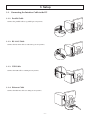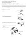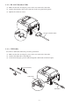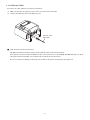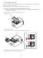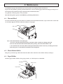
1
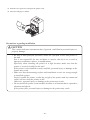
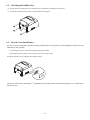
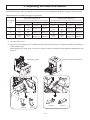
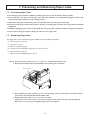
THERMAL PRINTER
TSP650II SERIES
Hardware Manual
Caution Symbol
These symbols are located near the thermal print head.
Because the thermal print head is hot immediately after printing, do not touch it. Static
electricity can damage the thermal print head. To protect the thermal print head from
static electricity, do not touch it.
This symbol is located near the cutter.
Never touch the cutter blade, as you could injure your fingers.
This symbol is located near the peripheral drive connector.
Do not connect this to a telephone.
This symbol is located near the screws securing the case or the protective plate, which
should not be opened by individuals other than service personnel. Individuals, other
than service personnel, should not remove these screws. High voltage areas in the case
can be dangerous.
Federal Communications Commission
Radio Frequency Interference
Statement
This device complies with Part 15 of the FCC Rules. Operation is subject to the following two conditions:
(1) This device may not cause harmful interference, and
(2) this device must accept any interference received, including interference that may cause undesired operation.
NOTE: This equipment has been tested and found to comply with the limits for a Class A digital device, pursuant to
Part 15 of the FCC Rules. These limits are designed to provide reasonable protection against harmful interference
when the equipment is operated in a commercial environment. This equipment generates, uses and can radiate
radio frequency energy and, if not installed and used in accordance with the instruction manual, may cause harmful
interference to radio communications. Operation of this equipment in a residential area is likely to cause harmful
interference in which case the user will be required to correct the interference at his own expense.
FCC WARNING
Changes or modifications not expressly approved by the party responsible for compliance could void the user’s
authority to operate the equipment.
For compliance with the Federal Noise Interference Standard, this equipment requires a shielded cable.
For RF interference suppression, if a ferrite core is provided with this device, affix it to the interface cable.
This statement will be applied only for the printers marketed in U.S.A.
Statement of
The Canadian Department of Communications
Radio Interference Regulationst
This Class A digital apparatus complies with Canadian ICES-003.
Cet appareil numérique de la classe A est conforme à la norme NMB-003 du Canada.
The above statement applies only to printers marketed in Canada.
< For Bluetooth models >
Federal Communications Commission
Radio Frequency Interference
Statement
This device complies with Part 15 of the FCC Rules and RSS-Gen of IC Rules. Operation is subject to the following
two conditions:
(1)this device may not cause harmful interference, and
(2)this device must accept any interference received,including interference that may cause undesired operation.
This equipment complies with FCC/IC radiation exposure limits set forth for an uncontrolled environment and
meets the FCC radio frequency (RF) Exposure Guidelines in Supplement C to OET65 and RSS-102 of the IC radio
frequency (RF) Exposure rules. This equipment has very low levels of RF energy that it deemed to comply without
maximum permissive exposure evaluation(MPE). But it is desirable that it should be installed and operated keeping
the radiator at least 20cm or more away from person's body (excluding extremities: hands,wrists,feet and ankles).
This statement will be applied only for the printers marketed in U.S.A and Canada.
CE MARKING WARNING
Hereby, Star Micronics Co., Ltd. declares that this device is in compliance with the essential requirements and other
relevant provisions of Directive 1999/5/EC.
Notice) This device can be operated in all European countries.
Italy:
The public use is subject to general authorisation by the respective service provider.
Norway: This subsection does not apply for the geographical area within a radius of 20 km from the centre of NyAlesund.
This statement will be applied only for the printers marketed in Europe.
Trademark acknowledgments
TSP650II : Star Micronics Co., Ltd.
Notice
• All rights reserved. Reproduction of any part of this manual in any form whatsoever, without STAR’s express
permission is forbidden.
• The contents of this manual are subject to change without notice.
• All efforts have been made to ensure the accuracy of the contents of this manual at the time of going to press.
However, should any errors be detected, STAR would greatly appreciate being informed of them.
• The above notwithstanding, STAR can assume no responsibility for any errors in this manual.
Copyright © 2013-2014 Star Micronics Co., Ltd..
TABLE OF CONTENTS
1. Unpacking and Installation.......................................................................... 1
1-1.Unpacking..................................................................................................... 1
1-2. Notes about Installation................................................................................ 1
2. Parts Identification and Nomenclature........................................................ 2
3. Setup............................................................................................................. 3
3-1. Connecting the Interface Cable to the PC. . ..................................................... 3
3-2. Connecting the Interface Cable to the Printer................................................ 4
3-3. Connecting the AC Adapter........................................................................... 7
3-4. Turning the Power On . . .................................................................................. 8
3-5. Connecting to a Peripheral Device................................................................. 8
3-6. Loading a Paper Roll.. .................................................................................... 9
3-7. Bluetooth Setting (For Bluetooth Interface Model only) . . .................................... 12
3-8. Setup Precautions........................................................................................ 17
4. Attaching the Accessories........................................................................... 19
4-1. Attaching the Holder Plate . . ......................................................................... 19
4-2. Attaching the Rubber Feet........................................................................... 21
4-3. Switch Cover Installation. . ........................................................................... 21
5. Adjusting the Near-end Sensor.................................................................. 22
6. Error Indicators.......................................................................................... 23
6-1. Recoverable errors....................................................................................... 23
6-2. Unrecoverable errors................................................................................... 23
7. Preventing and Removing Paper Jams....................................................... 24
7-1. Preventing Paper Jams................................................................................. 24
7-2. Removing Paper Jams.................................................................................. 24
7-3. Releasing the Cutter Lock............................................................................ 25
8. Maintenance................................................................................................ 26
8-1. Thermal Head. . ............................................................................................ 26
8-2. Platen Rubber Roller................................................................................... 26
8-3. Paper Holder............................................................................................... 26
1. Unpacking and Installation
1-1.Unpacking
After unpacking the unit, check that all the necessary accessories are included in the package.
Paper roll
Paper roll guide
CD-ROM
Safety Instruction
&
Setup sheet
Printer
Switch blind
Rubber feet
Screws
Holding plate
* Accessories vary depending on the model and the
region where the printer was purchased.
1-2. Notes about Installation
1. Choose a firm, level surface where the printer will not be exposed to vibration.
2. Make sure that the printer is connected to a reliable power outlet. It should not be on the same electric circuit as copiers, refrigerators, or other appliances that cause power spikes.
3. The power outlet you plan to connect to for power should be nearby and unobstructed.
4. Make sure that the printer is not exposed to direct sunlight.
5. Make sure that the printer is well away from heaters and other sources of extreme heat.
6. Do not locate the printer in a badly ventilated or dusty environment.
7. Make sure that the room where you are using the printer is not too humid.
8. This device employs a DC motor and switches that have an electrical contact point.
Avoid using the device in environments where silicon gas can become volatile.
9. Use the printer within the boundaries indicated in the environmental requirements. Even when the ambient temperature and humidity are within the specifications, avoid radical changes in environmental conditions. The suitable
operating temperature range is as follows:
Operating temperature: 5°C to 45°C
10. When disposing of the printer, obey local regulations.
-1-
2. Parts Identification and Nomenclature
Printer cover
Cover open lever
Open to replace paper.
Do not open while printing.
Use this lever to open the
printer cover.
Power switch
Control panel
Turns the printer on
and off.
Features lamps that indicate printer
status and a button for operating
the printer.
FEED button
TSP650
POWER ERROR
When the printer is online, pressing
this button feeds the paper roll.
FEED
ERROR lamp (red)
POWER lamp (green)
Lights when the printer is online.
This lamp also indicates errors, in
combination with other lamps.
Interface connector
Connects to a host PC
through a cable.
Lights when the cover is open.
This lamp also indicates errors, in
combination with other lamps.
Peripheral drive connector
Connects to peripheral devices
such as cash drawers.
Do not connect this to a telephone line.
-2-
Power inlet
Connects to an optional
AC adapter.
3. Setup
3-1. Connecting the Interface Cable to the PC
3-1-1. Parallel Cable
Connect the parallel cable to a parallel port on your PC.
3-1-2. RS-232C Cable
Connect the RS-232C cable to a RS-232C port on your PC.
3-1-3. USB Cable
Connect the USB cable to a USB port on your PC.
3-1-4. Ethernet Cable
Connect the Ethernet cable to a USB port on your PC.
-3-
3-2. Connecting the Interface Cable to the Printer
Printer cables are not included in the package.
Obtain an appropriate cable that complies with the specifications beforehand.
Because the appropriate interface cable differs depending on the system that you are connecting the printer to, contact
the dealer that you bought the product from if you are unsure about what cable to use.
Before connecting or disconnecting an interface cable, be sure to disconnect the AC adapter’s power cord from the outlet.
3-2-1. Parallel Interface Cable
Ferrite core
To connect a parallel cable, follow the procedure given below.
(1) Make sure the printer is turn off.
(2) Affix the ferrite core onto the cable as shown in the illustration.
Interface cable
5 cm
(maximum)
(3) Pass the fastener through the ferrite core.
Fastener
(4) Loop the fastener around the cable and lock it. Use scissors to cut
off any excess.
Pull and cut
(5) Connect the interface cable to the connector on the rear panel of
the printer.
(6) Fasten the connector clasps.
Parallel interface cable
-4-
3-2-2. RS-232C Interface Cable
(1) Make sure that the AC adapter’s power cord is not connected to the outlet.
(2) Connect the interface cable to the connector on the rear panel of the printer.
(3) Tighten the connector screws.
RS-232C interface cable
3-2-3. USB Cable
To connect a USB cable, follow the procedure given below.
(1) Make sure that the AC adapter’s power cord is not connected to the outlet.
(2) Connect the USB cable to the USB port.
(3) As shown in the figure, pass the cable through the cable hooks to hold it in place.
4 cm (maximum)
Cable hook
USB cable
-5-
3-2-4. Ethernet Cable
To connect the cable, follow the procedure given below.
(1) Make sure that the AC adapter’s power cord is not connected to the outlet.
(2) Connect the Ethernet cable to the Ethernet port.
Ethernet cable
IFBD-HE07
g Link disconnection detection feature
The Ethernet interface model is equipped with a link disconnection detection feature.
If the printer is turned on when an Ethernet cable is not connected to it, the POWER and ERROR lamps are simultaneously turned on and off at 4-second intervals to indicate the disconnection.
Be sure to connect the Ethernet cable from a PC or hub to the printer, and then turn the printer on.
-6-
3-3. Connecting the AC Adapter
Note: Before connecting or disconnecting the AC adapter, make sure that the printer and all the devices connected
to it are turned off.
Then remove the power cord from the outlet.
(1) Connect the AC adapter to the power cord.
(2) Connect the AC adapter to the connector on the printer.
(3) Insert the power cable plug into an AC outlet.
CAUTION
When disconnecting the cable, take hold of the cable
connector to pull it out. Releasing the lock makes it easy
to disconnect the connector.
Pulling the cable excessively could cause damage to the
connector.
Note: We recommend that you use the standard AC adapter and power cord.
If you are not using the optional AC adapter (PS60A-24B1 series) and are instead preparing your own power
supply, note the following points.
• Use a power supply that is 24 VDC ± 10% and 2.1 A or more.
(Select a power supply with current capacity that is appropriate for the actual printing ratio.)
• Use a power supply that supports with SELV output or LPS (Limited Power Source).
• Take into consideration the noise in the environment that the printer is installed in, and take appropriate measures to protect the printer from static electricity, AC line noise, etc.
-7-
3-4. Turning the Power On
Connect the power cord according to the procedure in section 3-3, “Connecting the AC Adapter”.
Turn on the power switch, which is on the left side of the printer.
The POWER lamp on the control panel will light.
Power switch
3-5. Connecting to a Peripheral Device
You can connect a peripheral device to the printer using a modular plug.
Follow the procedure given below.
1) Make sure that the AC adapter’s power cord is not connected to the outlet.
2) Connect the modular jack plug to the peripheral drive connector on the rear panel of the printer.
Connect the other end of the cable to the modular jack of the peripheral device.
CAUTION: Do not connect a telephone line to the peripheral drive connector. Doing so may cause the printer
to malfunction. Also, for safety purposes, do not connect a wire that may carry excessive voltage to
the peripheral drive connector.
-8-
3-6. Loading a Paper Roll
Use a paper roll that complies with the printer specifications.
(1) Push the cover open lever, and open the printer cover.
Cover open lever
(2) Load the paper roll into the printer in the direction indicated by the figure, and pull the leading edge of the paper
straight toward you.
Paper roll
(3) Push on both sides of the rear cover to close it.
ote 1:Be careful not to pull the paper out at an angle, because doing so may cause the paper to jam or skew.
N
2:Be sure not to close the printer cover by pushing only one side.
3:Be careful not to get your fingers caught when opening or closing the printer cover.
4:After the printer cover is closed, the printer performs initial operations (from paper feeding to paper
cutting). Do not open the printer cover until the initial operations are complete.
-9-
3-6-1. Compliant Paper Roll Specifications
Paper thickness
53 μm to 85 μm
Paper width
79.5 ± 0.5 mm
57.5 ± 0.5 mm
External dimensions
• Roll diameter
Max. f 83 mm
• Take up paper roll width
+0.5
80 +0.5
- 1 mm / 58 - 1 mm
Core inner and outer diameters
Inner diameter f 12 ± 1 mm, external diameter f 18 ± 1 mm
Printed surface
Outer edge of roll
Note 1: Do not glue or tape the paper roll and shaft core together.
2: Do not fold the tail end of the paper.
3: For details on recommended thermal paper, see the following webpage.
http://www.starmicronics.com/support/
- 10 -
3-6-2. Changing the Paper Width
When using 57.5 mm width paper rolls, attach the supplied paper roll guide to the printer. When you change the effective
print width (paper roll width), change the printer utility’s memory switch setting.
For details, see the printer utility help.
(1) Insert the paper roll guide firmly into the slot in the printer labeled "r58" as shown in the figure below.
Paper roll guide
(2) Secure the paper roll guide in place by pushing the section marked as “A” in the figure.
A
Note1: Do not insert the paper roll guide into the slot labeled "r 65".
It may cause problems.
2:Do not change the paper width while the printer is in use.
The amount of wear on the thermal head, rubber roller, and cutter varies depending on the paper width.
This varying amount of wear may cause problems in printing and cutting.
- 11 -
3-7. Bluetooth Settings (For Bluetooth Interface Models only)
RST button
PAIR button
<LED>Indicates the status of the Bluetooth interface.
RST PAIR
Green (on): Not connected.
Green (flashing): Ready to start pairing.
Blue (on): Connected.
Purple (flashing): Auto connection ON.
LED
Pair the printer with the master device by following the procedure below.
3-7-1. Pairing using SSP (Simple Secure Pairing) [Default]
(1) After turning the printer's power switch on, press and hold the PAIR button on the rear interface of the printer for 5
seconds or more, and then release it. The LED will flash green.
PAIR button
T
RS
IR
PA
T
RS
IR
PA
(2) Pairing will be possible for 60 seconds from when the LED begins flashing green.
During this time, perform pairing from the master device.
Device name: Star Micronics (default)
(3) After performing pairing, wait until the LED stops flashing green, or turn the printer off and back on again, to enable
the connection.
In the iOS devices, after pairing, the LED will automatically begin flashing blue, and the printer will be automatically
connected.
(4) Connect to the printer from the master device application and perform printing. If the printing is successful, the
pairing process has been completed.
Note: The printer performs various processes immediately after connecting to or disconnecting from a master
device.
Please wait approximately 0.1 seconds after connecting, and approximately 0.5 seconds after disconnecting,
before beginning communications with the printer. This wait will ensure that the next action you perform
is executed correctly.
- 12 -
3-7-2. Pairing using PIN code
Enter the following information in the master device if it does not support SSP, or when otherwise necessary.
PIN:
1234 (default)
Device name: Star Micronics (default)
It is recommended that you change the PIN code for greater security.
For details regard changing the PIN code, please see the “Software Manual -Star Bluetooth Utility- ”.
3-7-3. Auto Connection Function (iOS only)
Each time the wireless connection is disconnected while communicating with upper-level iOS devices including iPad over
Bluetooth, it is necessary to move back to the Bluetooth setting screen in the upper-level iOS device and tap the desired
printer name again to build a connection. This is an iOS specification.
In order to save this labor, this printer is equipped with the Auto Connection function that automatically requests a connection from an upper-level iOS device that was connected to the printer last time.
The default setting of this function may differ according to the printer model you are using.
Confirm the default settings for your printer, as well as the use examples for ON/OFF settings, and then make the settings
to match your purpose.
You can also check the current ON/OFF setting by performing self-printing.
< Confirmation procedure by self-printing >
(1) While the printer cover is closed, hold down the FEED button
on the operation panel, and then turn on the power switch.
TSP650
POWER ERROR
(2) Self-printing starts, and the settings for F/W Version, DipFEED
Switch, Memory Switch, and so on are printed.
(3) If you keep holding down the FEED button after self-printing
is complete, the current ON/OFF settings are printed after the
interface information.
Caution: If "Auto Connection function" is set to ON when using devices other than iOS, a Bluetooth communication with the printer may fail. To use devices other than iOS, such as the Android/Windows devices,
make sure you turn off the "Auto Connection" function before using the printer.
For information on how to set up this function, see "3-7-4. Setting up Auto Connection".
- 13 -
See the table below for details of Auto Connection setting.
Auto Connection ON
Auto Connection OFF
Reconnecting without changing
the parent device
After the printer is turned on, it
automatically connects to the last
parent device that was connected.
After turning on the printer, tap
this printer's name on the Bluetooth settings screen on the parent device.
Changing the connected parent
device
Disconnect the Bluetooth connection in such a way as to turn OFF
the power to the upper-level device automatically connected.
After turning on the printer, establish a pairing with a desired
upper-level device.
Then, establish a pairing with a
desired upper-level device.
Example (recommended)
When connecting directly to the
printer from one parent device.
- 14 -
When using the printer with multiple parent devices.
3-7-4. Setting up Auto Connection
uSetting up from the Main Unit for the TSP650II
Note :The following procedure explains how to change the Auto Connection function setting from ON to OFF.
If you want to change it from OFF to ON, please follow the same procedure.
(1) When paper is loaded in the printer and it is turned on, the [POWER] LED(green) on the front of the printer
turns on.
(2) If you hold down the [RST] button on the back of the printer for at more than five seconds, initial operations are
performed in the same way as when the power is turned on, and the LEDs on the front of the printer flash. If you
press the [RST] button when the printer is placed upright, place it horizontally again while the LED is flashing.
RST button
T
RS
IR
PA
T
RS
IR
PA
(3) The following information is printed. After that, turn the printer off and then back on again to set "Auto Connection" to OFF.
< Current Setting >
Auto Connection : OFF
To enable this setting, turn
Printer Power OFF and turn ON.
(4) To make sure "Auto Connection" is set to OFF correctly, perform self-printing as described in "3-7-3. Confirmation
procedure by self-printing”.
Note : Only Bluetooth Firmware Version 2.0 or later allows you to switch ON/OFF by pushing the [RST] button. The Bluetooth Firmware version can be confirmed by self-printing. (For more information, see "3-7-3.
Confirmation procedure by self-printing”.)
uSetting from the Software
After pairing your device and the TSP650II, change "Auto Connection" in the following application provided by our company.
l iOS: Download "Star Setting Utility" from the following Web site.
http://www.star-m.jp/prjump/000003.html
l Android: Download "Star Setting Utility" from the following Web site.
http://www.star-m.jp/prjump/000004.html
l Windows: Download "Star Bluetooth Utility" from the following Web site.
http://www.star-m.jp/prjump/000006.html
- 15 -
3-7-5. Resetting Bluetooth Settings
The PIN code, device name, and other settings can be reset by following the procedure given below.
(1) Use a fine pointed pen or other similar object to press and hold the RST button. While holding the RST button, turn
the printer's power switch on.
(2) The reset process will begin, and the LED at the front of the printer will flash green. When the settings have been
reset, the LED will stop flashing.
(3) Turn the printer's power switch off, and delete the pairing settings from the master device.
RST button
T
RS
IR
PA
T
RS
IR
PA
“Made for iPod” ,“Made for iPhone” and “Made for iPad” mean that an electronic accessory has been designed to
connect specifically to iPod, iPhone, or iPad, respectively, and has been certified by the developer to meet Apple
performance standards.
Apple is not responsible for the operation of this device or its compliance with safety and regulatory standards.
iPod is a trademarks of Apple Inc., registered in the U.S. and other countries. iPod touch, iPad and iPhone are
trademark of Apple Inc.
iPod, iPhone and iPad compatibility list
Made for • iPod touch (5th generation)
• iPad Air
• iPod touch (4th generation)
• iPad (4rd generation)
• iPad (3rd generation)
• iPhone 5S
• iPad 2
• iPhone 5C
•iPad
• iPhone 5
• iPhone 4S
• iPhone 4
• iPad mini with Retina display
• iPad mini
Note: as of July. 2014
- 16 -
3-8. Setup Precautions
Caution Symbol
These symbols are located near the thermal print head.
Because the thermal print head is hot immediately after printing, do not touch it. Static
electricity can damage the thermal print head. To protect the thermal print head from
static electricity, do not touch it.
This symbol is located near the cutter.
Never touch the cutter blade, as you could injure your fingers.
This symbol is located near the peripheral drive connector.
Do not connect this to a telephone.
This symbol is located near the screws securing the case or the protective plate, which
should not be opened by individuals other than service personnel. Individuals, other
than service personnel, should not remove these screws. High voltage areas in the case
can be dangerous.
WARNING
l
If you notice smoke or strange odors coming from this product, turn the power switch off immediately, and remove
the power cord from the AC outlet. For repairs, contact the dealer that you bought the product from.
l
Never attempt to repair the product yourself. Doing so can be dangerous.
l
Never disassemble or modify the product. Doing so may result in injury, fire, or electric shock.
l
On models that have cutters or tear bars, do not touch the cutter blade or the tear bar.
- There is a cutter or tear bar inside the paper outlet slot. Never put your hand in the slot regardless of whether or
not the printer is in operation.
- You must open the printer cover to replace paper. However, because the cutter blade or tear bar is located inside
of the cover, be careful not to bring your face and hands too close to the blade or tear bar when the cover is open.
l
During and immediately after printing, the area around the print head is very hot. Don’t touch it because you could
be burned.
l
Be sure to turn off the printer before performing maintenance on the cutter. Failing to do so is dangerous.
CAUTION
l
We recommend that you unplug the printer from the power outlet whenever you do not plan to use the printer for
long periods.
Because of this, you should locate the printer so that the power outlet it is plugged into is nearby and easy to access.
l
If an AC cord set is supplied with the product, the power cord that is included has been specially designed for the
product.
l
Make sure that the printer and the PC are turned off and unplugged from their AC outlets before you make connections.
l
Do not connect a telephone line to the peripheral drive connector, which is used for devices such as cash drawers.
Doing so may cause the printer to malfunction. Also, for safety purposes, do not connect a wire that may carry excessive voltage to the peripheral drive connector.
- 17 -
l
Do not open the printer covers while the printer is printing or cutting.
l
Do not pull out paper when the printer cover is closed.
l
If liquid or foreign objects (such as coins and paper) enter the inside of the printer, turn the power switch off,
disconnect the power cord from the AC outlet, and consult the dealer that you bought the product from.
Continuing to use the printer may lead to a short-circuit, which may cause electric shock or fire.
l
The heating element and the driver IC of the thermal print head are easily damaged. Do not touch them with metal
objects, sandpaper, etc.
l
Do not touch the thermal print head heating element. Doing so may make it dirty, which will decrease the printing
quality.
l
Static electricity can damage the driver IC and other components of the thermal print head. Avoid touching it directly.
l
Do not operate the printer if there is moisture (which has been caused by condensation or another factor) on the
front surface of the head.
l
The printing quality and the thermal print head’s service life cannot be guaranteed if paper other than the recommended paper is used.
In particular, thermal paper containing Na+, K+, or C1- may drastically reduce the service life of the thermal print head.
We recommend that you use paper with the following maximum ion densities: 500 ppm of Na+, 150 ppm of K+, and
300 ppm of Cl-.
For details on recommended thermal paper, see the following webpage.
http://www.starmicronics.com/support/
CAUTION
Wireless Communication
l
Do not use the device where using wireless devices is prohibited or may cause interference or danger.
l
The radio waves generated by the device may interfere with the operation of electronic medical devices. If you are
using any electrical medical device, contact its manufacturer for the restrictions on the use of the device.
l
Security functionality for Bluetooth is installed in this product. Configure the security settings according to the
manual (available on the Star Micronics website) to reduce the risk of security issues.
l
This device supports Bluetooth.
Since this functionality may be limited by local regulations, first review the radio laws specific to the country in
which the product will be used.
l
Below is a list of laws this device has been approved by. As Star Micronics is committed to constant innovation, revisions may be made without an announcement. Access the Star Micronics website for the latest listing of approvals.
l
Please refer to Star Micronics website for the latest information and manuals.
- 18 -
4. Attaching the Accessories
The following accessories are necessary when mounting the printer to a wall.
• Holder plate and two flangeless screws
The following accessories are necessary when positioning the printer vertically.
• Four rubber feet
The following accessories do not necessarily have to be attached. Attach it if necessary.
• Switch cover
4-1. Attaching the Holder Plate
<Precoutions>
n The holder plate is attached to the printer using the included screws and is hooked onto screws that are installed
into the wall.
n The screws on the wall are not included.
Use commercially available screws (4 mm diameter) that are suitable for the wall material (wood, steel beam,
concrete, etc.).
n The printer’s weight is approximately 2.4 kg when the largest diameter roll paper is loaded.
Use screws on the wall that have both shear strength and pulling-out strength to withstand a force of at least
12 kgf (118 N).
(1) Attach the holding plate to the printer. Then tighten the two screws that were supplied to secure it in place.
(2) Position the printer over the screws, etc., on the wall and then slide it downward to set it in place.
After setting the printer in place, check the screws on the wall again to make sure that they are able to support the
printer’s weight.
2∼ 3mm
- 19 -
(3) Push the cover open lever, and open the printer cover.
(4) Insert the roll paper as shown.
Precautions regarding installation
CAUTION
This caution indicates information that, if ignored, could lead to personal injury or
property damage.
• Be sure to have qualified personnel install the specified screws and printer to
the wall.
Star is not responsible for any accidents or injuries that occur as a result of
improper installation, misuse, or modifications.
Especially when installing the printer at a high location, make sure that the
printer is securely installed to the wall.
If the printer is not installed securely and falls, personal injury or damage to the
printer may result.
• Make sure that the mounting surface and installation screws are strong enough
to install the printer.
Securely install the printer so that the weight of the printer and any connected
cables will not cause the printer to fall.
Otherwise, personal injury or damage to the printer may result.
• Do not install the printer in an unstable location or a location that is exposed to
vibration and shocks.
If the printer falls, personal injury or damage to the printer may result.
- 20 -
4-2. Attaching the Rubber Feet
(1) Ensure that any soiling has been completely wiped off before attaching the rubber feet.
(2) Attach the four rubber feet in the positions shown in the figure.
4-3. Switch Cover Installation
It is not necessary to install the switch cover. Only install it if it is necessary for you. By installing the switch cover, the
following become possible.
• Preventing the power switch from being operated by mistake.
• Ensuring that other people can not easily operate the power switch.
Install the switch cover as shown in the diagram below.
The power switch can be turned ON ( | ) and OFF (O) by inserting a narrow instrument (ball pen etc.) in the holes in
the switch cover.
- 21 -
5. Adjusting the Near-end Sensor
Use the following procedure to adjust the near-end sensor so it is compatible with the size of paper roll you are using.
Adjustment value according to the paper you are using
Paper Width
(μm)
Horizontal (standard) Layout
Vertical Layout or Wall-Mount
ø12 inner diameter / ø18 outer diameter core roll paper
ø12 inner diameter / ø18 outer diameter core roll paper
Detected diameter (mm)
Detected diameter (mm)
Remaining paper length (m)
Remaining paper length (m)
Level 1
Level 2
Level 1
Level 2
Level 1
Level 2
Level 1
Level 2
53
Approx.
ø23
Approx.
ø29
Approx. 3.0
Approx. 7.7
Approx.
ø29
Approx.
ø23
Approx. 7.7
Approx. 3.0
65
Approx.
ø23
Approx.
ø29
Approx. 2.5
Approx. 6.3
Approx.
ø29
Approx.
ø23
Approx. 6.3
Approx. 2.5
85
Approx.
ø23
Approx.
ø29
Approx. 1.9
Approx. 4.8
Approx.
ø29
Approx.
ø23
Approx. 4.8
Approx. 1.9
(1) Open the printer cover.
(2) Insert the tip of a ballpoint pen or similar object into the hole of the adjuster, and then push and slide the adjuster
to the desired setting.
When changing the setting, make sure that the position of the hole is aligned with the alignment mark indicated by
the arrow.
[Horizontal Layout]
(Level 1)
(Level 2)
[Vertical Layout or Wall-Mount]
- 22 -
(Level 1)
(Level 2)
6. Error Indicators
6-1. Recoverable errors
Check the recovery conditions. The printer can be recovered while maintaining its current status.
Error description
Thermal head high
temperature detection
error
POWER
ERROR
Recovery condition
Flashes at 1 second intervals
Off
The printer recovers automatically when the thermal head cools.
Cover open error
On
On
The printer recovers when you close the cover.
Near end error
On
Flashes at 4 second
intervals
The printer recovers when you set a new paper roll and
close the rear cover.
Paper out error
On
Flashes at 0.5-second intervals
The printer recovers when you set a new paper roll and close the
cover.
Ethernet link disconnection detection (*1
(Physical link disconnection)
Flashes at 4 seond intervals.
Flashes at 4 seo-nd
intervals.
Connect an Ethernet cable. For details, see section 3-2-4, "Ethernet Interface Cable."
Ethernet link disconnection detection (*1
(IP address lost)
Flashes at 0.25 Flashes at 0.25 seoSet the correct IP address and restart the printer.
seo-nd intervals.
nd intervals.
(*1: IFBD-HE07 only
6-2. Unrecoverable errors
Turn the printer off, check the recovery conditions, and then turn the printer back on.
If the same error occurs after you turn the printer back on, the printer needs to be repaired.
Error description
POWER
ERROR
Cause
Recovery condition
Paper cutting in progress error
After you restart the printer, the
printer recovers when the mobile
cutter returns to its home position.
(Note 3, 4)
Flashes at 1 second intervals
Flash memory access error
-
Off
Flashes at 1.5
second intervals
This is not a recoverable error.
-
SRAM error
Off
Flashes at 2
second intervals
RAM access error
-
Head thermistor error
Off
Flashes at 3 second intervals
Detection of head thermistor
error
-
Power voltage error
Off
Flashes at 4
second intervals
Detection of power voltage
error
Check the condition of the power
supply, and restart the printer.
Cutter error
Off
Flashes at
0.25-second
intervals
Flash memory error
Off
EEPROM error
ote 1: If an unrecoverable error occurs, turn the power off immediately.
N
2: A power voltage error may be a result of a power supply malfunction.
3: If the paper is jammed, turn the power off, clear the jammed paper, and then turn the power back on.
For details, see section 6-2, “Removing Paper Jams”.
4: If the mobile cutter cannot return to its home position or the printer cannot perform initial operations,
manually unlock the cutter. For details, see section 6-3, “Releasing the Cutter Lock”.
If other unrecoverable errors occur, contact the dealer that you bought the product from for repairs.
- 23 -
7. Preventing and Removing Paper Jams
7-1. Preventing Paper Jams
l
To avoid paper jams and other problems, feed the paper at least 1 mm (8 dot lines) before printing.
l
If you want to use the cutter, to avoid paper jams and other problems, we recommend a margin of at least 5 mm
from the end of the printed area to the cutting position.
l
When you set the paper roll into the printer, do not pull out the end of the paper at an angle.
l
Do not touch the paper roll when the printer is printing or feeding paper or before the cut operation has finished
completely.
l
Holding or pulling the paper while it is being fed may cause paper jams, improper cutting, or improper line breaks.
l
Do not remove the paper while it is being cut. This can cause a paper jam.
7-2. Removing Paper Jams
If a paper jam occurs, remove the paper according to the procedure given below.
(1) Turn the power switch off.
(2) Open the rear cover.
(3) Remove the jammed paper.
(4) Load the paper roll straight, and gently close the rear cover.
(5) Turn the power switch on.
Make sure that the ERROR lamp is not lit.
Note1: If you cannot open the rear cover, see section 6-3, “Releasing the Cutter Lock”.
2: Because the thermal head is hot immediately after printing, do not touch it.
Thermal head
3: Do not pull on the paper with the rear cover closed. Doing so may cause damage to or deformation of
parts such as the thermal head and the rubber roller.
4: Push on both sides of the rear cover to close it securely.
Pushing the center section of the cover may cause only one side of the cover to be closed completely.
If the rear cover is not closed completely, the printer may not print.
- 24 -
7-3. Releasing the Cutter Lock
If the auto cutter locks up, restart the printer by turning the power switch off and then back on. A typical locked cutter
will be restored when you restart the printer.
If restarting the printer does not release the locked cutter, follow the procedure below.
Note1: Be sure to turn off the printer before performing maintenance on the cutter.
2: When removing jammed paper, be careful not to damage the printer. In particular, the thermal head is easily damaged, so do not touch it.
(1) Make sure that the power cable is unplugged from the outlet.
(2) Remove the front cover.
Front cover
Cutter unit
(3) Remove the jammed paper.
(4) Turn the knob in front of the cutter until the drive knife reaches the home position.
Printer cover
NG
Knob
Home position
Drive knife
OK
Home position
(5) Open the rear cover, remove the jammed paper, and reset the paper.
(6) Reattach the front cover, and turn the power switch on.
- 25 -
Drive knife
8. Maintenance
Accumulation of paper dust and dirt may cause the printer to not print portions of characters.
To prevent such problems, perform periodic maintenance, such as removing paper dust from the paper transport section and removing the blackened paper dust from the thermal head surface.
As a guideline, clean the printer every six months.
Note: Turn the printer’s power switch off before performing maintenance.
8-1. Thermal Head
To remove the blackened paper dust that has accumulated on the thermal head surface, wipe it clean with a cotton swab
(or soft cloth) dipped in alcohol (ethanol, methanol, or isopropyl).
Thermal head
Note 1:The thermal head is easily damaged.
Be sure to clean the thermal head with a soft cloth, and be careful not to damage the head.
2: Do not clean the thermal head immediately after printing, when the thermal head is hot.
3: Be careful of static electricity while cleaning the thermal head. Static electricity can damage the head.
4: Turn the power on only after the alcohol has dried completely.
8-2. Platen Rubber Roller
Using a dry, soft cloth, wipe off the dirt from the rubber roller. Clean the entire rubber roller by rotating it.
8-3. Paper Holder
Clean the paper holder of debris, dust, paper particles, etc. that may have accumulated.
Rubber roller
Paper holder
- 26 -
English:
Hereby, STAR MICRONICS CO.,LTD. declares that this
Wireless Device is in compliance with the essential
requirements and other relevant provisions of Directive
1999/5/EC.
Deutsch:
[German]
Hiermit erklärt STAR MICRONICS CO.,LTD., dass sich
das Gerät Wireless Device in Übereinstimmung mit
den grundlegenden Anforderungen und den übrigen
einschlägigen
Bestimmungen der Richtlinie 1999/5/EG befindet.
Svenska:
[Swedish]
Härmed intygar STAR MICRONICS CO.,LTD. att denna
Wireless Device står I överensstämmelse med de väsentliga
egenskapskrav och övriga relevanta bestämmelser som
framgår
av direktiv 1999/5/EG.
Español:
[Spanish]
Por medio de la presente STAR MICRONICS CO.,LTD. declara
que el Wireless Device cumple con los requisitos esenciales
y cualesquiera otras disposiciones aplicables o exigibles
de la Directiva 1999/5/CE.
Português:
[Portuguese]
STAR MICRONICS CO.,LTD. declara que este Wireless Device
está conforme com os requisitos essenciais e outras
disposições da Directiva 1999/5/CE.
Français:
[French]
Par la présente STAR MICRONICS CO.,LTD. déclare que
l'appareil Wireless Device est conforme aux exigences
essentielles et aux autres dispositions pertinentes de la
directive
1999/5/CE.
Eesti:
[Estonian]
Käesolevaga kinnitab STAR MICRONICS CO.,LTD.
seadme Wireless Device vastavust direktiivi 1999/5/EÜ
põhinõuetele ja nimetatud direktiivist tulenevatele teistele
asjakohastele sä
tetele.
Ελληνική:
[Greek]
ΠΡΟΕΙΔΟΠΟΙΗΣΗ:
ΜΕ ΤΗΝ ΠΑΡΟΥΣΑ STAR MICRONICS CO.,LTD. ΔΗΛΩΝΕΙ ΟΤΙ
Wireless Device ΣΥΜΜΟΡΦΩΝΕΤΑΙ ΠΡΟΣ ΤΙΣ ΟΥΣΙΩΔΕΙΣ
ΑΠΑΙΤΗΣΕΙΣ ΚΑΙ ΤΙΣ ΛΟΙΠΕΣ ΣΧΕΤΙΚΕΣ ΔΙΑΤΑΞΕΙΣ Τ
ΗΣ ΟΔΗΓΙΑΣ 1999/5/ΕΚ.
Slovensky:
[Slovak]
STAR MICRONICS CO.,LTD. týmto vyhlasuje, že Wireless
Device spĺňa základné požiadavky a všetky príslušné
ustanovenia Smernice 1999/5/ES.
Slovensko:
[Slovenian]
STAR MICRONICS CO.,LTD. izjavlja, da je ta Wireless Device
v skladu z bistvenimi zahtevami in ostalimi relevantnimi
določili direktive 1999/5/ES.
Česky:
[Czech]
STAR MICRONICS CO.,LTD. tímto prohlašuje, že tento
Wireless Device je ve shodě se základními požadavky a
dalšími príslušnými ustanoveními smernice 1999/5/ES.
Magyar:
[Hungarian]
Alulírott, STAR MICRONICS CO.,LTD. nyilatkozom, hogy
a Wireless Device megfelel a vonatkozó alapvetõ
követelményeknek és az 1999/5/EC irányelv egyéb
elõírásainak.
Български:
[Bulgarian]
това Безжично устройство е в съответствие със
задължителните изисквания и другите приложими
разпоредби на Директива 1999/5/EC.
Suomi:
[Finnish]
STAR MICRONICS CO.,LTD. vakuuttaa täten että Wireless
Device tyyppinen laite on direktiivin 1999/5/EY oleellisten
vaatimusten ja sitä koskevien direktiivin muiden ehtojen
mukainen.
Polski:
[Polish]
Italiano:
[Italian]
Con la presente STAR MICRONICS CO.,LTD. dichiara che
questo Wireless Device è conforme ai requisiti essenziali ed
alle altre disposizioni pertinenti stabilite dalla direttiva
1999/5/CE.
Niniejszym STAR MICRONICS CO.,LTD. oświadcza, że
Wireless Device jest zgodny z zasadniczymi wymogami
oraz pozostałymi stosownymi postanowieniami Dyrektywy
1999/5/EC.
Malti:
[Maltese]
Dansk:
[Danish]
Undertegnede STAR MICRONICS CO.,LTD. erklærer
herved, at følgende udstyr Wireless Device overholder de
væsentlige krav og øvrige relevante krav i direktiv 1999/5/
EF.
Hawnhekk, STAR MICRONICS CO.,LTD., jiddikjara li dan
Wireless Device jikkonforma mal-ħtiġijiet essenzjali u ma
provvedimenti oħrajn relevanti li hemm fid-Dirrettiva
1999/5/EC.
Latviski:
[Latvian]
Ar šo STAR MICRONICS CO.,LTD. deklarē, ka Wireless Device
atbilst Direktīvas 1999/5/EK būtiskajām prasībām un citiem
ar to saistītajiem noteikumiem.
Nederlands:
[Dutch]
Hierbij verklaart STAR MICRONICS CO.,LTD. dat het toestel
Wireless Device in overeenstemming is met de essentiële
eisen en de andere relevante bepalingen van richtlijn
1999/5/EG.
Lietuvių :
[Lithuanian]
Šiuo STAR MICRONICS CO.,LTD. deklaruoja, kad šis Wireless
Device atitinka esminius reikalavimus ir kitas 1999/5/EB
Direktyvos nuostatas.
STAR MICRONICS CO.,LTD. Head Office
20-10 Nakayoshida, Suruga-ku, Shizuoka-shi, Shizuoka, 422-8654, Japan
Tel. + 81-54-263-1111 Fax. + 81-54-263-1057
STAR Quality Technical Center
18-12 Nakayoshida, Suruga-ku, Shizuoka-shi, Shizuoka, 422-8001, Japan
Tel. + 81-54-263-1303 Fax. + 81-54-263-6650
Declaration of Conformity
Application of Council Directive(s)
1999/5/EC of 9 Mar 1999
2004/108/EC of 15 Dec 2004
2006/95/EC of 12 Dec 2006
2011/65/EU of 8 Jun 2011
Standard(s) to which Conformity is Declared
RADIO :
EN 300 328 V1.7.1
EN 50371 : 2002
EMISSION :
EN 301 489-1 V1.9.2
EN 301 489-17 V2.1.1
EN 55022 : 2010
EN 61000-3-2 : 2006 / +A1 +A2 : 2009
EN 61000-3-3 : 2008
IMMUNITY :
EN 55024 : 2010
SAFETY :
EN 60950-1 : 2006 / +A12 : 2011
EN 62311 : 2008
ENVIRONMENT: EN 50581: 2012
Manufacturer’s Name
Manufacturer’s Address
Star Micronics Co.,Ltd.
20-10 Nakayoshida, Suruga-ku, Shizuoka-shi,
Shizuoka 422-8654 Japan
Importer’s Name
Importer’s Address
Star Micronics Europe Ltd.
Star House, Peregrine Business Park, Gomm Road,
High Wycombe, Bucks. HP13 7DL, U.K.
Type of Equipment
Model Name
Ref. Radio Report No.
Ref. EMC Report No.
Ref. Safety Cert. No.
Ref. Environ. Report No.
Thermal Printer
TSP650
F092137E3
F092137E4 , 88-S116-EMC
JP-10575-M1-UL (IEC)
TSP650-RoHS-01
I , the undersigned , hereby declare that the equipment specified above
conforms to the above Directive(s) and Standard(s).
Place
High Wycombe - U.K.
Date
Mar. 13 , 2013
Year of 1st CE mark
'07
(Signature)
David Pearce
Technical Manager
(Full Name)
(Position)
http://www.starmicronics.com/support/