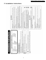
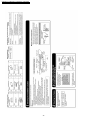
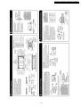
1
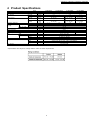
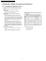
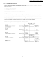
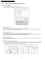
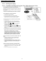
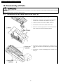
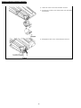
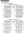
ORDER NO. RAC0602010C2
Multi Air Conditioner
CS-ME7EB1E
CS-ME10EB1E
CS-ME12EB1E
CS-ME14EB1E
Please file and use this manual together with the service manual for Model No. CU-3E23CBPG, CU4E27CBPG, Order No. RAC0209005C2 and CU-3E18EBE, Order No. RAC0503011C2.
CONTENTS
Page
Page
1 Safety Precautions
3
10.1. Simultaneous Operation Control
18
2 Features
5
10.2. Airflow Direction Control
19
3 Functions
6
10.3. Indoor Fan Control
20
3.1. REMOTE CONTROL
6
10.4. Drain Pump Control
22
3.2. INDOOR UNIT
7
10.5. Auto Restart Control
23
10.6. Other Indoor Unit Operation Functions
24
4 Product Specifications
5 Dimensions
9
10
11 Installation Instructions
31
5.1. Cassette Type
10
12 Disassembly of Parts
36
5.2. Grille
12
12.1. Detaching the fan motor and cross flow fan
36
6 Refrigeration Cycle Diagram
13
12.2. Detaching the drain pump
37
7 Block Diagram
14
12.3. Detaching the control board
37
8 Wiring Diagram
15
12.4. Detaching the louver motor
39
9 Electronic Circuit Diagram
16
10 Operation Details (Functions & Protection)
13 Technical Data
40
18
© 2006 Matsushita Electric Industrial Co., Ltd. All
rights reserved. Unauthorized copying and
distribution is a violation of law.
CS-ME7EB1E / CS-ME10EB1E / CS-ME12EB1E / CS-ME14EB1E
13.1. OPERATION CHARACTERISTICS
14 Exploded View & Replacement Parts List
40
14.1. Exploded View
45
45
14.2. Replacement Parts List
46
Operating instructions of this product can be referred at following Web site.
http://phaam.panasonic.com.my
2
CS-ME7EB1E / CS-ME10EB1E / CS-ME12EB1E / CS-ME14EB1E
1 Safety Precautions
3
CS-ME7EB1E / CS-ME10EB1E / CS-ME12EB1E / CS-ME14EB1E
4
CS-ME7EB1E / CS-ME10EB1E / CS-ME12EB1E / CS-ME14EB1E
2 Features
· Product
− A single OUTDOOR unit enables air conditioning of up to four separate rooms
Remarks:
1. At least two indoor units must be connected.
2. The total nominal cooling capacity of indoor units that will be connected to outdoor unit must be within connectable
capacity range of outdoor unit. (Shown in the above table)
Example: The below indoor units combination is not possible to connect CU-3E23CBPG. (Total nominal capacity
of indoor unit is between 5.0kW and 10.0kW)
1) Two CS-ME7EB1E only. (Total nominal cooling capacity is 4.4kW)
2) Three CS-ME14EB1E only. (Total nominal cooling capacity is 12.0kW)
− Inverter controlled for High energy efficiency and optimal comfort
− New refrigerant R410A is used for protecting ozone layer
− Lead - free P.C. Board
· Serviceability
− Self diagnosis
− Test Run at both Cooling and Heating rated frequency
· Built-in drain pump
− A drain pump is built in.
The pipe can rise to 200 mm above the drain outlet.
5
CS-ME7EB1E / CS-ME10EB1E / CS-ME12EB1E / CS-ME14EB1E
3 Functions
3.1.
REMOTE CONTROL
6
CS-ME7EB1E / CS-ME10EB1E / CS-ME12EB1E / CS-ME14EB1E
3.2.
INDOOR UNIT
7
CS-ME7EB1E / CS-ME10EB1E / CS-ME12EB1E / CS-ME14EB1E
8
CS-ME7EB1E / CS-ME10EB1E / CS-ME12EB1E / CS-ME14EB1E
4 Product Specifications
Model
Item
Power Source
Air Volume
Cooling
Heating
Cooling
(Power)
Heating
(Power)
Noise Level
Moisture Removal
Refrigeration
piping
Connection
Liquid
Gas
Type of pipe
Type of Indoor/Outdoor connecting cable
Drain opening
Dimensions
Net Weight
Fan
Type
Motor
Type
Output
Heat exchanger
Adjustments
Switches
Timer
Temperature
Air filter
CS-ME7EB1E
m3/min.
m3/min.
dB(A)
(dB)
dB(A)
(dB)
L/h
mm
mm
mm
mm
mm
kg
W
CS-ME10EB1E
CS-ME12EB1E
CS-ME14EB1E
Cassette Type
Outdoor power (single 230V 50Hz)
9.1
9.6
9.5
10.1
10.9
9.8
Hi:40(53)
Hi:41(54)
Hi:42(56)
Lo:32(45)
Lo:32(45)
Lo:32(45)
Hi:42(55)
Hi:42(56)
Hi:44(57)
Lo:32(45)
Lo:32(45)
Lo:34(47)
1.3
1.6
1.8
2.3
6.35 (1/4") Flare to the main unit
9.52 (3/8") Flare to the main unit
CZ-3F
4 x 1.5 mm2 flexible cord, type designation 245 IEC 57 (H05RN-F)
VP20
Height 185 x Width 770 x Depth 360
9.8
10.5
Cross-flow fan
DC brushless motor (ARW50A8P30AC)
4P 25W 40V A98258
Plate fin forced-draft
Wireless remote control
Timer with ON and OFF times programmable
Electronic thermostat
PP honeycomb
* Specifications are subject to change without notice for further improvement.
9
CS-ME7EB1E / CS-ME10EB1E / CS-ME12EB1E / CS-ME14EB1E
5 Dimensions
5.1.
Cassette Type
10
CS-ME7EB1E / CS-ME10EB1E / CS-ME12EB1E / CS-ME14EB1E
11
CS-ME7EB1E / CS-ME10EB1E / CS-ME12EB1E / CS-ME14EB1E
5.2.
Grille
12
CS-ME7EB1E / CS-ME10EB1E / CS-ME12EB1E / CS-ME14EB1E
6 Refrigeration Cycle Diagram
13
CS-ME7EB1E / CS-ME10EB1E / CS-ME12EB1E / CS-ME14EB1E
7 Block Diagram
CS-ME7EB1E/ME10EB1E/ME12EB1E/ME14EB1E
14
CS-ME7EB1E / CS-ME10EB1E / CS-ME12EB1E / CS-ME14EB1E
8 Wiring Diagram
15
CS-ME7EB1E / CS-ME10EB1E / CS-ME12EB1E / CS-ME14EB1E
9 Electronic Circuit Diagram
CS-ME7EB1E CS-ME10EB1E CS-ME12EB1E CS-ME14EB1E
16
CS-ME7EB1E / CS-ME10EB1E / CS-ME12EB1E / CS-ME14EB1E
17
CS-ME7EB1E / CS-ME10EB1E / CS-ME12EB1E / CS-ME14EB1E
10 Operation Details (Functions & Protection)
10.1. Simultaneous Operation Control
1. Operation modes which can be selected using the remote
control unit: Automatic, Cooling, Soft Dry, Heating, Fan operation
mode.
2. Types of operations modes which can be performed
simultaneously
· Cooling operation and cooling, Dry or fan operation
· Heating operation and heating operation
“Waiting” denotes the standby status in which the operation
lamp LED blinks (ON for 2.5 sec. and OFF for 0.5 sec.), and
the fan is stopped.
3. Types of operation modes which cannot be performed
simultaneously
· While a cooling operation is in progress, a heating operation
cannot be performed by an indoor unit in another room.
In the room where the operation button for cooling was pressed
first, the operation is continued. In the room where the operation
button for heating was pressed afterward, the operation lamp of
the indoor unit blinks, where the attempt is made to establish the
heating operation. Its fan is stopped, and the air does not
discharged.
· While a heating operation is in progress, a cooling operation
cannot be performed by an indoor unit in another room.
In the room where the operation button for heating was pressed
first, operation is continued. In the room where the operation
button for cooling was pressed afterward, the operation lamp of
the indoor unit blinks, where the attempt is made to establish the
cooling operation. Its fan is stopped, and the air does not
discharged.
4. Operation mode priority control
* In the fan mode, priority is transferred to a non-priority unit.
Note
C: Cooling operation mode
· The operation mode designated first by the indoor unit has
priority.
D: Soft Dry operation mode
· If the priority indoor unit stops operation or initiates the fan
operation, the priority is transferred to other indoor units.
F: Fan operation mode
H: Heating operation mode
18
CS-ME7EB1E / CS-ME10EB1E / CS-ME12EB1E / CS-ME14EB1E
10.2. Airflow Direction Control
The following shows how louver operation changes depending on the direction set with the AIR SWING button and other operating
conditions.
Cooling and Dry
Heating
· The louver stops at the CLOSE position when the power switch or breaker is ON.
· The louver stops at their current position when the power switch or breaker is OFF.
· Move the horizontal airflow direction control louver manually.
19
CS-ME7EB1E / CS-ME10EB1E / CS-ME12EB1E / CS-ME14EB1E
10.3. Indoor Fan Control
· The following shows how fan speed changes depending on the setting made with the FAN SPEED button and other operating
conditions.
· Actual fan speed may differ from that you set with remote control.
20
CS-ME7EB1E / CS-ME10EB1E / CS-ME12EB1E / CS-ME14EB1E
21
CS-ME7EB1E / CS-ME10EB1E / CS-ME12EB1E / CS-ME14EB1E
10.4. Drain Pump Control
Basic operation
· The drain pump starts 50 seconds after the indoor unit starts or the thermostat comes on (i.e., 10 seconds after the fan
motor starts).
The drain pump stops 30 seconds after the indoor unit stops or the thermostat turns off.
· The drain pump repeats a cycle of on for 30 seconds then off for between 50 and 90 seconds as long as the unit is
operating. Operation while the unit is off is determined by the difference between the temperature setting and the room
temperature.
Float switch operation
· When the float switch turns on for 10 seconds continuously, the thermostat of the indoor unit turns off and the drain pump
operates continuously.
· When the float switch stays on for 150 seconds continuously, the drain pump and indoor unit stop and the timer lamp
flashes indicating an H21 error.
22
CS-ME7EB1E / CS-ME10EB1E / CS-ME12EB1E / CS-ME14EB1E
10.5. Auto Restart Control
· if there is a power failure, operation will automatically be restarted when the power is resumed. It will start with the previous
operation mode and airflow direction. (Time Delay Safety Control is valid)
1. Control start conditions
<1> The 24-hour timer must not be set.
<2> The sleep timer must not be set.
Auto restart control is not available when timer or sleep mode is set.
2. Description of control
<1> In the case of manual operation, the operation mode, temperature setting, fan speed and airflow direction before the power
is turned off are restored.
<2> In the case of automatic operation, after the power is restored operation starts with the determination of the mode.
<3> While the air conditioner odour clear timer has been set, the setting is cancelled, and operation is transferred to the mode
before the power is turned off.
<4> While the air conditioner odour clear operation (with timer / without timer setting) are being performed, both of these
operations are completed, and operation is transferred to the operation mode prior to these operations.
Example: When the power is turned off during an outdoor unit cooling operation
23
CS-ME7EB1E / CS-ME10EB1E / CS-ME12EB1E / CS-ME14EB1E
10.6. Other Indoor Unit Operation Functions
10.6.1.
Auto button
Proceed with operation when the air conditioner is stopped.
(When the auto button is pressed during operation, the air conditioner is stopped.)
1. Emergency operation
Press the auto button and release it within 5 seconds to perform emergency operation.
Under normal condition (failure is not occurred) automatic operation is performed. In the event of a failure that still enables
operation to be performed, emergency operation is performed.
2. Forced cooling operation
Keep pressing the auto button until one beep sounds to perform the automatic cooling operation.
The air conditioner does not operate for 2 minutes if the room temperature is low (intake temperature below 16 °C) so
just wait. The forced operation is performed after the 2 minutes have elapsed.
3. Forced heating operation
First press the auto button until one beep sounds, and then set it to OFF.Now press the auto button until two beeps sound to
perform the automatic heating operation.
4. Select Remote Control Transmission Code
· There are 4 types of remote control transmission code could be selected and stored in EEPROM of indoor unit. The indoor
unit will only operate when received signal with same transmission code from remote control. This could prevent signal
interference when there are 2 more indoor unit installed nearby together.
· To change remote control transmission code, short or open jumpers at the remote control printed circuit board.
24
CS-ME7EB1E / CS-ME10EB1E / CS-ME12EB1E / CS-ME14EB1E
10.6.2.
Drain Test
When installing the unit and you want the drain pump to operate independently, press the DRAIN TEST switch to operate it for
about 5 minutes.
25
CS-ME7EB1E / CS-ME10EB1E / CS-ME12EB1E / CS-ME14EB1E
10.6.3.
Self Diagnosis display
10.6.3.1. BreakDown Self Diagnosis Function (Three Digits Alphanumeric Code)
· Once abnormality has been detected during operation, the unit
will immediately stop its operation. (Timer LED blinks.)
· Although timer LED goes off when power supply is turned off, if
the unit is operated under a breakdown condition, the LED will
light up again.
· In operation after breakdown repair, error code is not displayed.
The last error code (abnormality) will be saved in IC memory.
· Timer LED Blinking in Abnormal Operation:
1. Automatically stops the operation.
2. Timer LED on display of the indoor unit blinks.
3. The LED will be off if the unit is turned off or the Error
RESET button on the remote controller is pressed.
· To display memorized error (Protective operation) status:
1. Turn the unit on.
2. Press the CHECK button on the remote controller for
continuously 5 seconds or more with a pointed object to
appear “--” on the display.
or
button on the remote
3. Press the “TIMER”
controller to appear “H00” on the display. Signal is
transmitted to the main unit.
button (When the
button is
4. Press the “TIMER”
pressed, the display goes back.) repeatedly and slowly until
Beeps sound (about 5 seconds intermittently) is heard from
main unit.
5. Then, displayed error code matches to the error code saved
in unit memory. The power LED on the main unit also lights
up.
Note: When the CHECK button is pressed
continuously for 5 seconds again, or when no
operation continues for 30 seconds, or when the
RESET button on remote controller is pressed
with a pointed object, the display is cancelled.
· To clear memorized error (Protective operation) status after
repair:
1. Press the AUTO button in main unit continuously for
5seconds or more and release it. (Test run / Pump
downoperation: Beep sound)
2. Press the CHECK button on remote controller for about 1
second with a pointed object to transmit signal to main unit.
A beep sound is heard from main unit and the data is
cleared.
· Temporary Operation (Depending on breakdownstatus)
1. Press the ON/OFF button after selecting Cooling or Heating
operation. (Receiving Beep sound is heard andthe TIMER
LED blinks.)
2. The unit can temporarily be used until repaired.
26
CS-ME7EB1E / CS-ME10EB1E / CS-ME12EB1E / CS-ME14EB1E
10.6.3.2. Error Code
Symbol
Diagnosis
H11 Indoor / Outdoor
abnormal
communication
H12
Indoor unit capacity
unmatched
H14
Intake air temp.
sensor
H16
Outdoor Current
Transformer
Diagnosis method
This error occurs when indoor/outdoor unit communication fails to be established after 30 seconds or more.
<Diagnosis checkpoint>
1. Measure the voltage of the indoor/outdoor unit communication cables, and check whether the voltage is being
supplied properly to the outdoor unit or whether it is being returned from the outdoor unit to the indoor units.
This error occurs when wrong in the total connection capacity and wrong connection in each capacity.
The error is determined within 2 minutes after the power is turned on.
<Diagnosis checkpoint>
1. Check the total capacity of the units connected and check that the models are compatible for connection.
This error occurs when the intake air temperature has exceeded above 46°C continuously for 2 minutes or
dropped below -54°C continuously for 5 seconds during operation.
<Diagnosis checkpoint>
1. This error occurs when a temperature which is impossibly high or low from a normal standpoint has been
detected.
Check the sensor, and if open-circulating (more than 500k ohms) or short-circulating (less than 6.5k ohms)
is not found, defective contact of the connector is possible.
When the total current has dropped below the set current level continuously for 20 seconds during operation
beyond the set capacity, operation is stopped. Three minutes later, operation is started up again, and when the
trouble occurs on 4 successive occasions, the error occurs (the timer lamp blinks).
<Diagnosis checkpoint>
1. Check the refrigerating cycle: Gas may be leaking (the amount of refrigerant is extremely low).
2. Check the control P.C. Board: Check for a broken wire (open-circuit) in the current transformer. (If opencircuit is found, replace the control P.C. Board.)
H19
Indoor fan motor
mechanism lock
In the case of a scroll compressor (DC motor), H16 is detected only when the regular compressor is
operating.
High-voltage PWM: When a state in which the fan motor speed is not synchronized with the control signal has
been detected on 7 successive occasions:
Low-voltage PAM: When the fan lock detection signal has been detected on 7 successive occasions or it has
been detected continuously for 25 seconds or when a state in which the fan motor speed is not synchronized
with the control signal has been detected on 7 successive occasions:
The error occurs (the timer lamp blinks).
<Diagnosis checkpoint>
1. Check the nature of the fan lockup trouble.
H21
Indoor float switch
abnormality
2. Check for disconnections of the fan motor connectors and for defects in contact, in the fan motor and in the
control P.C. Board.
Error occurs when the float switch is open for 150 seconds.
<Diagnosis checkpoint>
1. Drain blockage
2. Check the conductivity of float switch.
H23
H27
H28
3. Check that the resistance of the drain motor is about 200 ohms.
Indoor heat exchanger This error occurs when a temperature of under approximately -40°C or above approximately 80°C has been
temp. sensor
detected by the heat exchanger temperature sensor continuously for 5 seconds.
(This error is not detected during de-icing.)
<Diagnosis checkpoint>
1. This error occurs when a temperature which is impossibly high or low from a normal standpoint has been
detected.
Outdoor air temp.
sensor
Check the sensor, and if open-circuit (more than 500k ohms) or short-circuit (less than 2.5k ohms) is not
found, defective contact of the connector or a defective control P.C. Board is possible.
This error occurs when a temperature of under approximately -40°C or above approximately 150°C has been
detected by the outdoor air temperature sensor for 2 to 5 seconds. (This error is not detected during de-icing.)
<Diagnosis checkpoint>
1. This error occurs when a temperature which is impossibly high or low from a normal standpoint has been
detected.
Outdoor heat
exchanger temp.
sensor 1
Check the sensor, and if open-circuit (more than 500k ohms) or short-circuit (less than 0.5k ohms) is not
found, defective contact of the connector or a defective control P.C. Board is possible.
This error occurs when a temperature of under approximately -60°C or above approximately 110°C has been
detected by the heat exchanger temperature sensor for 2 to 5 seconds. (This error is not detected during deicing.)
<Diagnosis checkpoint>
1. This error occurs when a temperature which is impossibly high or low from a normal standpoint has been
detected.
Check the sensor, and if open-circuit (more than 500k ohms) or short-circuit (less than 0.5k ohms) is not
found, defective contact of the connector or a defective control P.C. Board is possible.
27
CS-ME7EB1E / CS-ME10EB1E / CS-ME12EB1E / CS-ME14EB1E
Symbol
Diagnosis
H30 Outdoor discharge
pipe temp. sensor
Diagnosis method
Disconnected discharge sensor
When the condensation temperature is higher than the discharge temperature + (plus) 6°C, a sensor
disconnection is detected, operation stops, and the error occurs (the timer lamp blinks).
<Diagnosis checkpoint>
1. This error occurs when a temperature which is impossibly high or low from a normal standpoint has been
detected.
H32
H34
H35
Check the sensor, and if open-circuit (more than 500k ohms) or short-circuit (less than 0.5k ohms) is not
found, defective contact of the connector or a defective control P.C. Board is possible.
Outdoor heat
This error occurs when a temperature of under approximately -60°C or over approximately 110°C has been
exchanger temp.
detected continuously for 2 to 5 seconds by the outlet temperature sensor of the heat exchanger.
sensor 2
<Diagnosis checkpoint>
(discharge pipe temp.) 1. This error occurs when a temperature which is impossibly high or low from a normal standpoint has been
detected.
Outdoor heatsink
temp. sensor
Drainage or drain
pump abnormality
Check the sensor, and if open-circuit (more than 500k ohms) or short-circuit (less than 0.5k ohms) is not
found, defective contact of the connector or a defective control P.C. Board is possible.
This error occurs when a temperature of under -43°C or above 80°C has been detected by the outdoor unit
radiator fin sensor continuously for 2 seconds.
<Diagnosis checkpoint>
1. This error occurs when a temperature which is impossibly high or low from a normal standpoint has been
detected.
Check the sensor, and if open-circuit (more than 500k ohms) or short-circuit (less than 0.5k ohms) is not
found, defective contact of the connector or a defective control P.C. Board is possible.
This error occurs if the float switch is open three times for 10 seconds or more during a twenty-minute period.
<Diagnosis checkpoint>
1. Drain blockage
2. Check the conductivity of float switch.
H36
H37
H39
H97
H98
Outdoor gas pipe
temp. sensor
Outdoor liquid pipe
temp. sensor
Abnormal indoor
operating unit or
standby units
Outdoor fan motor
mechanism lock
Indoor high pressure
protection
3. Check that the resistance of the drain motor is about 200 ohms.
This error occurs when a temperature of under -45°C or above approximately 149°C has been detected by the
outdoor unit gas side pipe temperature sensor continuously for 2 to 5 seconds.
<Diagnosis checkpoint>
1. This error occurs when a temperature which is impossibly high or low from a normal standpoint has been
detected.
Check the sensor, and if open-circuit (more than 500k ohms) or short-circuit (less than 0.5k ohms) is not
found, defective contact of the connector or a defective control P.C. Board is possible.
This error occurs when a temperature of under -45°C or above 149°C has been detected by the outdoor unit liquid
side pipe temperature sensor continuously for 2 seconds.
<Diagnosis checkpoint>
1. This error occurs when a temperature which is impossibly high or low from a normal standpoint has been
detected.
Check the sensor, and if open-circuit (more than 500k ohms) or short-circuit (less than 0.5k ohms) is not
found, defective contact of the connector or a defective control P.C. Board is possible.
This error occurs in rooms other than one in which indoor freezing error has occurred when the pipes have been
connected incorrectly, when an outdoor expansion valve is defective or when an expansion valve connector has
become disconnected.
When the fan motor speed detected when its maximum output is demanded is below 30 rpm. continuously for 15
seconds, the fan motor stops for 3 minutes and then restarted.
When this happens on 16 occasions (the error is cleared when the value is normal for 5 minutes), the H97
diagnostic symbol is stored in the memory, and the fan motor stops.
<Diagnosis checkpoint>
1. Check the nature of the fan lockup error.
2. Check for disconnections of the fan motor connectors and for defects in contact, in the fan motor and in the
control P.C. Board.
The restriction on the compressor frequency is started when the temperature of the indoor unit heat exchanger
source is between 50°C and 52°C, the compressor stops at a temperature from 62°C to 65°C, it is restarted 3
minutes later at below 62°C to 65°C, and the restriction on the compressor frequency is released at a temperature
between 48°C and 50°C. (No error occurs.)
<Diagnosis checkpoint>
1. Check the indoor unit heat exchanger temperature sensor (check for changes in its characteristics and check
its resistance): Symptoms include no hot start when operation is started, a failure of the thermostat to turn on
(no outdoor unit operation). And, frequent repetition of stopping and startup.
2. Check also for short-circuits indoors and clogging of the air filters.
28
CS-ME7EB1E / CS-ME10EB1E / CS-ME12EB1E / CS-ME14EB1E
Symbol
Diagnosis
H99 Indoor operating unit
freezing
Diagnosis method
The restriction on the compressor frequency is started when the indoor unit heat exchanger temperature is
between 8°C and 12°C. Operation stops if a temperature below 0°C continues for 6 minutes. Three minutes later,
operation is started up at a temperature from 3°C to 8°C. The restriction on the compressor frequency is released
at a temperature between 13°C and 14°C.
<Diagnosis checkpoint>
1. A cooling or dry mode operation conducted at a low outside air temperature is mainly to suspect:
this is not indicative of any malfunctioning.
If the outdoor air temperature rises during automatic operation in the winter months, the dry mode
operation is selected. The H99 diagnostic display also appears at such a time.
2. Check the refrigerating cycle: Gas may be leaking (the amount of refrigerant is low) or a pipe may be broken,
etc.
F11
F17
F90
3. Check also for short-circuits indoors and clogging of the air filters.
4-way valve switching When a difference of 0°C to 5°C has been detected between the outdoor unit heat exchanger temperature and
failure
liquid side pipe temperature on 5 occasions, the error occurs.
<Diagnosis checkpoint>
1. Check the 4-way valve coil: Check that no power is supplied to the coil during cooling and dry mode
operations, and that power is supplied during heating operation. Inspect the coil for broken wires (opencircuit).
Indoor standby units
freezing
2. If the coil trouble-free, the switching action of the 4-way valve may be defective.
When the difference of an intake temperature (room temperature sensor) and the indoor unit heat exchanger
temperature (piping sensor) is higher than 10°C or an indoor unit heat exchanger temperature of below -1°C has
been detected continuously for 5 minutes, operation stops. Three minutes later, it is started up, and the error
occurs when this has occurred on 3 consecutive occasions.
<Diagnosis checkpoint>
1. Check the refrigerating cycle: Expansion valve leakage
2. Check the indoor unit pipe temperature sensor. (Check for changes in its characteristics and check its
resistance.)
PFC circuit protection When a DC voltage over 393V to 424V has been detected on 16 occasions, this error occurs.
<Diagnosis checkpoint>
1. To check whether the shutting valve has been left close by mistake, operation is performed for one to several
minutes after the compressor has started up, F93 is stored in the memory as the symptom, and operation
stops.
2. Check the inverter circuit (for open-circuiting) in the control P.C. Board: Check the IPM base current (6
locations) within 3 minutes after the power has been turned back on. As the symptom, F93 is stored in the
memory 30 seconds after the compressor has started up, and operation stops. The error occurs after 4
restarts.
3. Check for broken wires (for open-circuiting) in the compressor winding: Approximately 1 ohm under normal
conditions for each phase (same symptom as in 2.)
F91
F93
Refrigeration cycle
abnormality
4. Check the power supply voltage has been fluctuating or not.
When the compressor frequency is above 55 Hz and the current drops below the prescribed level continuously
for 7 minutes, operation stops, and it is restarted 3 minutes later.
When the compressor discharge temperature has exceeded the setting and the expansion valve has remained
fully open for 80 seconds, operation stops, and it is restarted 3 minutes later.
When the stopping described above has occurred on 4 occasions, operation stops, and the error occurs.
<Diagnosis checkpoint>
1. Check the refrigerating cycle: Gas may be leaking (more than one-half of the volume of the gas has gone).
The diagnosis displays resulting from a gas leak generally change in the following sequence depending on
the extent of the gas leak: H99
F97
F91
H16.
The range of this error (F91) is limited. (Compressor protection at the start of the season)
Compressor abnormal When a state in which the rotation of the compressor is not synchronized with the control signal has been
revolution
detected on 8 successive occasions, operation stops, and the error occurs.
<Diagnosis checkpoint>
1. To check whether the shutting valve has been left close by mistake, operation is performed for one to several
minutes after the compressor has started up, F93 is stored in the memory as the symptom, and operation
stops.
2. Check the inverter circuit (for open-circuit) in the control P.C. Board: Check the IPM base current (6 locations)
within 3 minutes after the power has been turned back on. As the symptom, F93 is stored in the memory 30
seconds after the compressor has started up, and operation stops. The error occurs after 4 restarts.
F96
3. Check for broken wires (open-circuit) in the compressor winding: Approximately 1 ohm under normal
conditions for each phase (same symptom as in 2.)
IPM (Power transistor When error occurs from the electrical parts radiation fin temperature sensor and OLP output during operation,
module) or
operation stops, and it is restarted 3 minutes later. If the trouble occurs on 4 occasions, operation stops, and the
compressor
error occurs.
overheating
<Diagnosis checkpoint>
1. Something may be interfering with the dissipation of the heat outdoors or the outdoor unit fan may be
defective. (The outdoor unit fan is not running.)
2. Defective IPM (Outdoor unit control P.C. Board)
3. Gas leaks. Shutting valve is not opened.
29
CS-ME7EB1E / CS-ME10EB1E / CS-ME12EB1E / CS-ME14EB1E
Symbol
Diagnosis
Diagnosis method
F97 Compressor high
This error occurs and operation stops when this happens on 6 occasions (it is cleared when the operation is
discharge temperature normal for 20 minutes).
<Diagnosis checkpoint>
1. Check the refrigerating cycle: Gas may be leaking (The amount of refrigerant is low). The stopping of the
outdoor unit from time to time is a symptom of this error.
2. When operation steps with this error occurs, check the compressor temperature sensor. (Check for changes
in its characteristics and check its resistance.)
3. Something may be interfering with the dissipation of the heat outdoors or the outdoor unit fan may be
defective. (The fan will not run because of open-circuiting.)
F98
F99
Total running current
protection
DC peak detection
(The protection may be activated by an overload, and the F97 error will remain stored in the memory.)
When the total current exceeds the setting (17A to 20A), frequency control is started, and if it then exceeds the
setting, operation stops, and the error occurs.
<Diagnosis checkpoint>
1. Check the AC voltage at the outdoor unit terminal board during operation: The voltage drop must be within
5% of the voltage when operation has stopped (±110% of rated voltage even during operation). If the voltage
drop exceeds 5% of if the voltage changes suddenly, inspect whether the power supply cord and
indoor/outdoor unit connection cables are too long or too small in diameter, etc.
2. Check whether something is interfering with the dissipation of the heat exchanger outdoors (during cooling
operation): Normally, the capacity is limited by the current so that outdoor unit doesn’t stop, and the
diagnostic display does not appear.
When "Output current error", which occurs when the prescribed current level is exceeded, has occurred on 16
consecutive occasions, operation stops, and the error occurs.
<Diagnosis checkpoint>
1. Check whether the compressor is defective (locked up or shorted winding). Check the outdoor unit control
P.C. Board.
30
CS-ME7EB1E / CS-ME10EB1E / CS-ME12EB1E / CS-ME14EB1E
11 Installation Instructions
31
CS-ME7EB1E / CS-ME10EB1E / CS-ME12EB1E / CS-ME14EB1E
32
CS-ME7EB1E / CS-ME10EB1E / CS-ME12EB1E / CS-ME14EB1E
33
CS-ME7EB1E / CS-ME10EB1E / CS-ME12EB1E / CS-ME14EB1E
34
CS-ME7EB1E / CS-ME10EB1E / CS-ME12EB1E / CS-ME14EB1E
35
CS-ME7EB1E / CS-ME10EB1E / CS-ME12EB1E / CS-ME14EB1E
12 Disassembly of Parts
High voltages are generated in the electrical parts area by the capacitor, Ensure that the capacitor has discharged sufficiently before proceeding
with repair work.
Failure to heed this caution may result in electric shocks.
12.1. Detaching the fan motor and cross flow fan
36
1)
Open the air inlet section of the front grille.
2)
Unscrew the 4 screws on the front grille, then disengage the
catches with a screwdriver and detach the front grille.
3)
Loosen the screw on the cover and detach the cover.
4)
Unscrew the 2 screws on the control section cover.
5)
Detach the connectors going from the control board to the drain
pump and from the receiver and display sections.
6)
Unscrew the screw and disengage the 2 catches on the air
outlet grille, then take out the drain pan plug to drain off excess
water.
7)
Unscrew the 4 screws and disengage the 5 catches on the
drain pan.
CS-ME7EB1E / CS-ME10EB1E / CS-ME12EB1E / CS-ME14EB1E
8)
Detach the air guide and unscrew the screw on the heat
exchanger.
9)
Detach the float switch and unscrew the 3 screws and
disengage the 2 catches on the fan motor holder.
10) Loosen the screw fixing the shaft between the cross flow fan
and the fan motor and detach the fan motor.
11) Remove the cross flow fan.
12.2. Detaching the drain pump
8) Unscrew the screw on the drain pump holder and detach it.
9) Detach the drain hose from the drain pump and remove the
drain pump.
12.3. Detaching the control board
1) Open the air inlet section of the front grille.
2) Unscrew the 4 screws on the front grille, then disengage the
catches with a screwdriver and detach the front grille.
37
CS-ME7EB1E / CS-ME10EB1E / CS-ME12EB1E / CS-ME14EB1E
3) Loosen the screw on the cover and detach the cover.
4) Unscrew the 2 screws on the control section cover and detach
all connectors.
5) Disengage the catch on the control board and remove it.
38
CS-ME7EB1E / CS-ME10EB1E / CS-ME12EB1E / CS-ME14EB1E
12.4. Detaching the louver motor
3) Loosen the screw on the cover and detach the cover.
4) Unscrew the 2 screws on the control section cover and detach
the connector for the louver motor.
5) Unscrew the screw and disengage the 2 catches on the air
outlet grille.
6) Unscrew the 2 screws on the louver motor on the back of the air
outlet grille and remove the louver motor.
39
CS-ME7EB1E / CS-ME10EB1E / CS-ME12EB1E / CS-ME14EB1E
13 Technical Data
13.1. OPERATION CHARACTERISTICS
40
CS-ME7EB1E / CS-ME10EB1E / CS-ME12EB1E / CS-ME14EB1E
41
CS-ME7EB1E / CS-ME10EB1E / CS-ME12EB1E / CS-ME14EB1E
42
CS-ME7EB1E / CS-ME10EB1E / CS-ME12EB1E / CS-ME14EB1E
43
CS-ME7EB1E / CS-ME10EB1E / CS-ME12EB1E / CS-ME14EB1E
44
CS-ME7EB1E / CS-ME10EB1E / CS-ME12EB1E / CS-ME14EB1E
14 Exploded View & Replacement Parts List
14.1. Exploded View
Note:
The above exploded view is for the purpose of parts disassembly and replacement.
The non-numbered parts are not kept as standard service parts.
45
CS-ME7EB1E / CS-ME10EB1E / CS-ME12EB1E / CS-ME14EB1E
14.2. Replacement Parts List
<Model: CS-ME7EB1E / CS-ME10EB1E / CS-ME12EB1E / CS-ME14EB1E>
Ref.
No.
1
2
3
4
5
7
8
9
10
11
12
13
14
16
17
18
19
20
21
22
23
24
25
26
27
31
34
35
36
37
38
40
43
44
45
46
47
48
49
50
51
52
54
55
56
57
58
59
62
63
64
65
66
Part Name & Description
FLOAT SWITCH
THERMAL FUSE
TERMINAL BOARD COMPLETE
SENSOR COMPLETE
TERMINAL PLATE FOR EARTH
LEAD WIRE COMPLETE (AS)
PC BOARD (MAIN)
PC BOARD (RECEIVER)
REMOTE CONTROL
AIR SWING MOTOR
FAN MOTOR
EVAPORATOR
DRAIN PUMP
DRAIN CAP
CHASSIS COMPLETE
FAN MOTOR BRACKET
PARTICULAR PLATE
PARTICULAR PIECE-1
PARTICULAR PIECE-2
PARTICULAR PIECE-3
DRAIN PUMP BRACKET
DISCHARGE GRILE COMPLETE
LOUVER
VERTICAL LOUVER
DECORATION PANEL
INSULATION SHEET
CROSS-FLOW FAN COMPLETE
CONTROL BOARD BOX
CONTROL COVER-1
CONTROL COVER-2
CONTROL COVER-3
HOLDER SENSOR
DRAIN TRAY
BELT
GUTTER
BUSHING FOR DRAIN PUMP-1
BUSHING FOR DRAIN PUMP-2
BUSHING
CAP (1/4)
CAP (3/8)
CAP
FLUCRUM
DRAIN PIPE
DRAIN HOSE COMPLETE
TUBE ASSY (3/8)
TUBE ASSY (1/4)
FLARE NUT (1/4)
FLARE NUT (3/8)
JOINT FOR DRAIN PIPE
ZNR
FUSE (250V 3A)
OPERATING INSTRUCTIONS
OPERATING INSTRUCTIONS
INSTALLATION INSTRUCTIONS
INSTALLATION INSTRUCTIONS
INSTALLATION INSTRUCTIONS
Q´ty
1
1
1
1
1
1
1
1
1
1
1
1
1
1
1
1
1
1
1
4
1
1
1
1
1
1
1
1
1
1
1
1
1
3
1
1
1
1
1
1
1
1
1
1
1
1
1
1
1
1
1
1
1
1
1
1
CS-ME7EB1E
CWA121207
CWA16C1020J
CWA28K1045J
CWA50C2100
CWA64C1005
CWA67C5811
CWA73C1946
CWA744084
CWA75C2610X
CWA98168
ARW50A8P30AC
CWB302119
CWB532010J
CWB82018
CWD50C260
CWD54232
CWD66238
CWD76223
CWD76225
CWD91197
CWD93938
CWA20C2490
CWE24423
CWE24C101
CWE35K1007
CWG10467
CWH02K117X
CWH10931
CWH131172
CWH13424
CWH13426
CWH32137
CWH40C1022
CWH4605004
CWH481002X
CWH50196
CWH50197
CWH50198J
CWH52061
CWH52062
CWH52160
CWH64C017
CWH851109
CWH85C1031
CWT022528
CWT024003
CWT25086
CWT25087
CWT29116
ERZVEAV511
XBA2C31TR0
CWF565240
CWF565241
CWF612962
CWF612963
CWF612968
Part No.
CS-ME10EB1E
CS-ME12EB1E
←
←
←
←
←
←
←
←
←
←
←
←
CWA73C1947
CWA73C1948
←
←
←
←
←
←
←
←
←
←
←
←
←
←
←
←
←
←
←
←
←
←
←
←
←
←
←
←
←
←
←
←
←
←
←
←
←
←
←
←
←
←
←
←
←
←
←
←
←
←
←
←
←
←
←
←
←
←
←
←
←
←
←
←
←
←
←
←
←
←
←
←
←
←
←
←
←
←
←
←
←
←
←
←
←
←
←
←
←
←
←
←
←
←
←
←
←
←
Remarks
CS-ME14EB1E
←
←
←
←
←
←
CWA73C2170
←
←
←
←
CWB30C1171
←
←
←
←
←
←
←
←
←
←
←
←
←
←
←
←
←
←
←
←
←
←
←
←
←
CWH501030
←
←
←
←
←
←
CWT022529
CWT024004
←
←
←
←
←
←
←
←
←
←
l
l
l
l
l
l
l
l
l
l
(Note)
· Other parts except the operation manual and the installation manual are parts for RoHS.
· "l" marked parts are recommended to be kept in stock.
· All parts are supplied from ACD, JAPAN (VENDER CODE : 00025800).
46
Printed in Japan