1
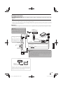
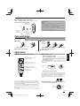
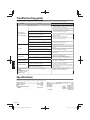
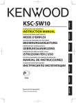
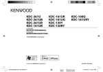
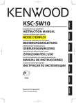
KSC-SW11
POWERED ENCLOSED SUBWOOFER
INSTRUCTION MANUAL
CAISSON D’EXTRÊME GRAVE AMPLIFIÉ
MODE D'EMPLOI
GEKAPSELTER SUBWOOFER MIT VERSTÄRKER
BEDIENUNGSANLEITUNG
SUBWOOFER MET SPANNINGSCIRCUIT
GEBRUIKSAANWIJZING
ENGLISH
FRANÇAIS
DEUTSCH
B61-1376_1_EN_00_KSC-SW11.indd 1
NEDERLANDS
© B61-1376-00/00 (W) KW
12.11.30 10:32:51 AM
IMPORTANT SAFETY INSTRUCTIONS
Caution: Read this page carefully to ensure safe operation.
WARNING
• Before mounting or wiring etc., be sure to remove the
wire from the battery minus terminal.
(Not doing so can cause shorts or fires.)
• When extending the ignition, battery, or ground wires,
make sure to use automotive-grade wires or other wires
with a 0.75mm2 (AWG18) or more to prevent wire deterioration and damage to the wore coating.
• To prevent a short circuit, never put or leave any metallic
objects (such as coins or metal tools) inside the speaker.
• In the event the unit generates smoke or abnormal smell,
immediately switch the power OFF. After this, please
contact your dealer or nearest service station as soon as
possible.
POWER OFF!
• Connect the speaker to DC 12V, negative ground.
• Do not attempt to open or modify the unit, for this could
cause fire hazard or malfunction.
• After taking the unit out of the polyethylene bag, be sure
to dispose of the polyethylene bag out of the reach of
children. Otherwise, they may play with the bag, which
could cause hazard of suffocation.
ENGLISH
CAUTION
2
• Installation and wiring of the product requires expert skill
and experience. To ensure safety, be sure to have your
dealer or specialist perform the installation and wiring.
• Do not install the speaker in a spot exposed to direct sunlight or excessive heat or humidity.
• Do not install the speakers in locations which may be
subject to water or moisture.
• Do not install the speakers in unstable locations or locations subject to dust.
• If the fuse blows, after checking to see if the wiring cord
has shorted, be sure to replace with the stipulated size
(amperage) fuse as displayed on the fuse box.
(Using fuses other than the stipulated size can cause
fires.)
Check the display!
To replace the fuse, refer to the vehicle instruction manual.
• To prevent a short circuit when replacing a fuse, disconnect the wiring harness at first.
• Do not use gasoline, naphtha, or any type of solvent to
clean the speaker. Clean by wiping with a soft, dry cloth.
• Connect the speaker wires to appropriate speaker connectors separately. Sharing the negative wire of the
speaker or grounding speaker wires to the metal body of
the car can cause this unit to fail.
• When making a hole under a seat, inside the trunk, or
somewhere else in the vehicle, check that there is nothing hazardous on the opposite side such as a gasoline
tank, brake pipe; or wiring harness, and be careful not to
cause scratches or other damage.
• For ground wire mounting, do not fasten the wire to
an airbag, steering or brake line system or other critical
safety unit bolts or nut.
(Can cause accidents.)
• When mounting, be sure to mount in a place that will not
interfere with driving or be dangerous to passengers during sudden braking etc.
(Cause of injury or accidents.)
• After installing the unit, check to make sure that electrical
equipment such as the brake lamps, turn signal lamps
and windshield wipers operate normally.
• The driver should always stop the vehicle in a safe place
before performing the following action.
– Remote control operation
• Do not use the product for purposes other than on-board
mounting.
Declaration of Conformity with regard to
the EMC Directive 2004/108/EC
Manufacturer:
JVCKENWOOD Corporation
3-12, Moriyacho, Kanagawa-ku, Yokohamashi, Kanagawa,
221-0022, Japan
EU Representative’s:
Kenwood Electronics Europe BV
Amsterdamseweg 37, 1422 AC UITHOORN,
The Netherlands
Information on Disposal of Old Electrical and Electronic Equipment (applicable for countries that
have adopted separate waste collection systems)
Products with the symbol (crossed-out
wheeled bin) cannot be disposed as household waste. Old electrical and electronic
equipment should be recycled at a facility
capable of handling these items and their
waste by products.
Contact your local authority for details in locating a
recycle facility nearest to you. Proper recycling and
waste disposal will help conserve resources whilst
preventing detrimental effects on our health and the
environment.
For Turkey
Bu ürün 28300 sayılı Resmi Gazete’de yayımlanan Atik
Elektrikli ve Elektronik Eşyalarin Kontrolü Yönetmeliğe
uygun olarak üretilmiştir.
Eski Elektrik ve Elektronik Ekipmanların İmha Edilmesi Hakkında Bilgi (ayrı atık toplama sistemlerini
kullanan ülkeleri için uygulanabilir)
Sembollü (üzerinde çarpı işareti olan çöp
kutusu) ürünler ev atıkları olarak atılamaz.
Eski elektrik ve elektronik ekipmanlar, bu
ürünleri ve ürün atıklarını geri dönüştürebilecek bir tesiste değerlendirilmelidir.
Yaşadığınız bölgeye en yakın geri dönüşüm tesisinin
yerini öğrenmek için yerel makamlara müracaat edin.
Uygun geri dönüşüm ve atık imha yöntemi sağlığımız
ve çevremiz üzerindeki zararlı etkileri önlerken kaynakların korunmasına da yardımcı olacaktır.
English
B61-1376_1_EN_00_KSC-SW11.indd 2
12.11.30 10:32:51 AM
Parts included
No.
Part Name
Outside Shape
Quantity
No.
Part Name
Outside Shape
Quantity
Remote control
1 (5 m / 16 ft)
1
Tapping screw
6 (ø 5 × 16 mm)
4
10-pin connector cord
2 (5 m / 16 ft)
1
Machine screw
7 (M4 × 5 mm)
4
Speaker cord
3 (4.3 m/ 14 ft)
1
Machine screw
8 (M3 × 8 mm)
2
4 Fixture A
2
1
5 Fixture B
1
Hook-and-loop fastener
9 (Double-side adhesive/
for Remote control)
Connection
Caution:
Before wiring, be sure to remove the wire from the negative terminal of the battery. After completing all wiring, check the
correct wirings again. After checking, connect the wire from the negative terminal of the battery.
■ Terminals of Subwoofer
POWER/SPEAKER INPUT terminal
■ Connecting the remote control unit
1 Remote control
ENGLISH
REMOTE terminal
Lights in blue.
Connect with the lock
part of remote control
jack facing down.
Lock part
When the power turns
ON, the illumination
lights.
Notes:
• Be sure to connect the supplied remote control unit.
• If the cord is not connected properly, the illumination on the remote control unit do not light up.
• Do not insert the remote control connector upside down or forcibly. Otherwise, malfunction may result.
English
B61-1376_1_EN_00_KSC-SW11.indd 3
3
12.11.30 10:32:53 AM
Connection
Speaker
p
input
p connection
Connect the subwoofer to the front speaker or rear speaker output cords of the center unit.
Notes:
• Read the instruction manuals for the connected components such as the center unit as well as this instruction manual.
• When the center unit incorporates a DSP, do not connect to the rear output, as the low-frequency reproduction effect may
be attenuated due to the DSP effect.
■ Examples
The following shows a typical connection for effective car stereo enjoyment. Connect your system by referring to the example.
Front or rear speaker
Center unit
Left
Right
Caution:
Do not distribute the cords in the
paths where they may be caught by
a vehicle part or damaged. Otherwise, an electric shock or a fire due to
short-circuiting may result.
Gray/Black
Gray
SP.R
INPUT
Fuse 10A
White
KSC-SW11
White/
Black
SP.L
INPUT
ENGLISH
2 10-pin connector cord
If there is no power control terminal in the center
unit, connect the blue/
white wire to the accessor y line (ignition key
switch ACC position line).
Do not bend the vinyl-coated section of the speaker cord. Otherwise,
malfunction may result.
Blue/White
3 Speaker cord
Car fuse box
If buzzing noise is heard from the speakers when the engine
is running, attach a line noise filter (commercially available)
to the power lead.
Ignition key
switch
Yellow
Car fuse box
(Main fuse)
Yellow
Black
※
Battery
4
LINE IN
GND
※
Caution:
Connect the black lead wire ground terminal directly with a screw
to an unpainted metal part of the vehicle. Turning the power ON
without connecting this terminal is linked to damage of the stereo
system. Be sure to connect it.
Also, painted metal panels etc., are not grounded and will not
function correctly. Be careful.
English
B61-1376_1_EN_00_KSC-SW11.indd 4
12.11.30 10:32:58 AM
RCA input
p connection
Connect the subwoofer to the subwoofer output (non-fader output) or the RCA jacks for the front output of the
center unit.
Notes:
• Read the instruction manuals for the connected components such as the center unit as well as this instruction manual.
• Please purchase an RCA cord that is commercially available separately.
• When the center unit incorporates a DSP, connect the subwoofer to the subwoofer output (non-fader output) or to the RCA
jacks for the front output. Do not connect to the RCA jacks for the rear output, as the low-frequency reproduction effect may
be attenuated due to the DSP effect.
■ Examples
The following shows a typical connection for effective car stereo enjoyment. Connect your system by referring to the example.
Caution:
Do not distribute the cords in the paths
where they may be caught by a vehicle part
or damaged. Otherwise, an electric shock or
a fire due to short-circuiting may result.
Center unit
(SUB WOOFER OUT,
Non-fader output)
KSC-SW11
Fuse 10A
If there is no power control terminal in the center
unit, connect the blue/
white wire to the accessor y line (ignition key
switch ACC position line).
2 10-pin connector cord
RCA cord
(Commercially available parts)
LINE IN
Blue/White
Car fuse box
Ignition key
switch
Yellow
Car fuse box
(Main fuse)
ENGLISH
If buzzing noise is heard from the speakers when the engine
is running, attach a line noise filter (commercially available)
to the power lead.
Yellow
Black
※
GND
※
Battery
Caution:
Connect the black lead wire ground terminal directly with a screw
to an unpainted metal part of the vehicle. Turning the power ON
without connecting this terminal is linked to damage of the stereo
system. Be sure to connect it.
Also, painted metal panels etc., are not grounded and will not
function correctly. Be careful.
Center unit
RCA cord
(Commercially
available parts)
KSC-SW11
When the center unit output is a single RCA jack, use
an RCA cord that converts the output into the two RCA
jacks as shown above. The subwoofer output will be
halved if the conversion cord is not used.
English
B61-1376_1_EN_00_KSC-SW11.indd 5
5
12.11.30 10:32:59 AM
Installation
Before fixing the speaker in its position, be sure to check the sound while it is connected preliminary.
Caution:
• When making a hole under a seat, inside the trunk, or somewhere else in the vehicle, check that there is nothing hazardous on
the opposite side such as a gasoline tank, brake pipe; or wiring harness, and be careful not to cause scratches or other damage.
• Install in a location that does not come in the way of driving, getting in or out of the vehicle and movement inside the vehicle compartment.
• Fix the product firmly so that it will not be moved by vibrations or impacts during driving.
■ Fixing the cord in place
Connect the 10-pin connector cord 2 and remote
control 1 to the speaker unit.
Fix the cords to the speaker unit with fixture B 5 and
fix in place with the machine screws 8.
8 Machine screw x 2
5 Fixture B
Prohibition!
Fix the cord so that it will not
protrude from the side of the
speaker
p
unit.
1 Remote control
2 10-pin connector cord
■ Fixing the subwoofer
The subwoofer can be fixed in two ways. Select the optimum attaching position of fixture A 4 according to the subwoofer
installation location.
Fixing method A
Fixing method B
ENGLISH
4 Fixture A
1
4 Fixture A
7 Machine screw x 4
4 Fixture A x 2
1
7 Machine screw x 4
4 Fixture A x 2
Caution:
This por tion becomes
slightly hotter than other
portions because it functions as the radiator of
the heat generated by
the amplifier.
Caution:
This por tion becomes
slightly hotter than other
portions because it functions as the radiator of
the heat generated by
the amplifier.
Attach the fixtures A 4 to the speaker unit securely
using the machine screws 7. Be careful so that the
connected cords do not get in between the speaker
unit and fixtures A 4.
Attach the fixtures A 4 to the speaker unit securely
using the machine screws 7. Be careful so that the
connected cords do not get in between the speaker
unit and fixtures A 4.
2
2
6 Tapping screw x 4
6 Tapping screw x 4
Drill four pilot holes for
ø 3.6 mm screws.
Drill the pilot holes for ø 3.6 mm screws on the sheet
metal section of the vehicle , and attach the speaker
unit to the vehicle using the tapping screws 6.
6
Drill four pilot holes for
ø 3.6 mm screws.
Drill the pilot holes for ø 3.6 mm screws on the sheet
metal section of the vehicle , and attach the speaker
unit to the vehicle using the tapping screws 6.
English
B61-1376_1_EN_00_KSC-SW11.indd 6
12.11.30 10:33:00 AM
■ Installing the remote control unit
Install the remote control unit on the vehicle by the
provided hook-and-loop fastener.
1 Remote control
(Rear panel)
Vehicle
9 Hook-and-loop
fastener
(Harder surface)
Caution:
Install the remote control unit in a position that does not
come in the way of driving operations.
Avoid installing it in a place subject to direct sunlight or
direct hot wind from the heater. Otherwise, the product
may be degraded and a fire hazard may result.
Remove dirt from the installation position before attaching the hook-and-loop fastener.
9 Hook-and-loop
fastener
(Softer surface)
Fuse exchange
g
Exchange with the specified capacity fuse.
Caution: Be sure to replace with same capacity (amperage) as displayed on the fuse. This product is 10A.
■ Removal
■ Insertion
Cover
Replacement
fuse 10 A
10
A
Fuse
Fuse holder
1 Open the cover.
2 Grasp the fuse and pull up.
1 Insert the fuse gently into the fuse holder and push
in all the way with your finger.
2 Close the cover.
Operation
p
■ Adjusting the sound
(Remote control operation)
Illumination
When the power turns ON, the
illumination lights.
1 Turn the FREQUENCY control knob to adjust the
cut-off frequency (frequencies higher than this
frequency are cut off).
VOLUME control knob
(Input sensitivity control knob)
Turn the FREQUENCY control knob to adjust the balance
between the bass from the rear speakers and the bass from this
unit as desired.
50 Hz
125 Hz
FREQUENCY control knob
(Cut-off frequency control knob)
Sound pressure
Low
level
Low
PHASE switch
(Phase select switch)
ENGLISH
■ Name of each part (Remote control )
High
High
Frequency
2 Adjust the low frequency phase.
The low frequency tone may be variable depending on the position of the unit, its orientation or the turn-over frequency. This
can be adjusted by changing the position of the PHASE switch.
Set this switch to either position according to your liking.
[0°] indicates the normal phase and [180°] means the reverse
phase.
The sound is output even when the remote control unit
is not connected, but the operations described in this
section are not available.
In this case, the volume, cut-off frequency and phase
are set to the predetermined default conditions, with
which the cut-off frequency is 125 Hz and the phase is
0º (positive).
3 Turn the VOLUME control knob to adjust the low
frequencies to the desired level.
To decrease
volume
To increase
volume
English
B61-1376_1_EN_00_KSC-SW11.indd 7
7
12.11.30 10:33:05 AM
Troubleshooting
g guide
g
Often, what appears to be a malfunction is due to user error. Before calling for service, please consult the following table.
Problem
Power cannot be
turned on (illumination does not light).
Cause
Remedy
• The fuse is blown.
• Check the (+)/(-) polarity of the power cord and
that the cords are not shorted, then replace
with a fuse with the rated capacity.
• Re-connect the cords correctly by referring to
the connection example (on page 4, 5).
• The power supply pin (yellow) of the 10-pin connection cord is not connected.
• Connect the cord correctly by referring to the
connection example (on page 4, 5).
• Attach the grounding terminal to the metallic
section of the vehicle (not a coated surface) by
tightly screwing it.
• Insert the connector all the way in.
• Check the connections of all cords, then connect the (-) cable to the battery.
• The power control pin (blue/white) of the 10-pin
connection cord is not connected.
• The grounding pin (black) of the 10-pin connection cord is not connected.
• The 10-pin connector is not plugged in completely.
No sound
Sound is small.
ENGLISH
Sound quality is bad
(sound is distorted).
Sound is unnatural.
Remote control does
not work.
• The negative (-) cable of the car battery is disconnected.
• Check the connections of all cords, then connect the (-) cable to the battery.
• The attenuator of the center unit is set to ON.
• Switch the attenuator OFF.
• The VOLUME control is set to the MIN position.
• Increase the volume to an optimum level (on
page 7).
• The speaker cords are connected improperly.
• Connect the cords correctly by referring to the
connection example (on page 4).
• Connection terminals are connected improperly.
• Insert the connectors or jacks all the way in to
the terminals.
• The input level is set to low.
• Turn the VOLUME control knob and set the input level to an optimum level.
• Connection terminals are connected improperly.
• Plug the cord into the REMOTE terminal.
• Check that the RCA cord is connected properly.
• The input level is set to high.
• Turn the VOLUME control knob and set the input level to an optimum level.
• The speaker cords are connected with incorrect
positive (+)/negative (-) polarity.
• Connect the cords correctly by referring to the
connection example (on page 4, 5).
• Attach the grounding terminal to the metallic
section of the vehicle (not a coated surface) by
tightly screwing it.
• The grounding pin (black) of the 10-pin connection cord is poorly contacted.
• The remote control cord is unplugged.
• Plug the cord into the REMOTE terminal.
• Insert the connector all the way in.
The illuminations on
the remote control
unit do not light.
Specifications
p
The following ratings and design are subject to change without notice.
Maximum output ..............................................................150 W
Frequency response ........................................... 35 Hz - 150 Hz
Cut-off frequency ............................................... 50 Hz - 125 Hz
Phase ................................................................................0˚, 180˚
Input sensitivity/impedance
LINE IN .............................................................. 50 mV / 22 kΩ
8
Power......................... DC 14.4 V (Operating range 11 V - 16 V)
Maximum current consumption ...................................... 8.5 A
Fuse capacity ........................................................................10 A
Sensitivity ............................................................ 110 dB (In car)
External size ......................................Width :
280 mm (11")
Height : 70 mm (2-3/4")
Depth : 190 mm (7-1/2")
Weight (net) .......................................................... 2.8kg (6.2 Ib)
English
B61-1376_1_EN_00_KSC-SW11.indd 8
12.11.30 10:33:08 AM
ENGLISH
English
B61-1376_1_EN_00_KSC-SW11.indd 9
9
12.11.30 10:33:09 AM