1
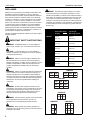
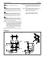
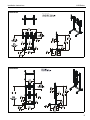
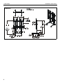
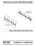
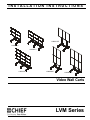
INSTALLATION INSTRUCTIONS
Instrucciones de instalación
Installationsanleitung
Instruções de Instalação
Istruzioni di installazione
Installatie-instructies
Instructions d´installation
LVM3X1UP
LVM2X2U
LVM3X2U
LVM3X3U
LVM2X2UP
LVM3X2UP
Video Wall Carts
Spanish Product Description
German Product Description
Portuguese Product Description
Italian Product Description
Dutch Product Description
French Product Description
LVM Series
LVM Series
Installation Instructions
DISCLAIMER
Milestone AV Technologies and its affiliated corporations and
subsidiaries (collectively "Milestone"), intend to make this
manual accurate and complete. However, Milestone makes no
claim that the information contained herein covers all details,
conditions or variations, nor does it provide for every possible
contingency in connection with the installation or use of this
product. The information contained in this document is subject
to change without notice or obligation of any kind. Milestone
makes no representation of warranty, expressed or implied,
regarding the information contained herein. Milestone assumes
no responsibility for accuracy, completeness or sufficiency of
the information contained in this document.
WARNING: Exceeding the weight capacity can result in
serious personal injury or damage to equipment! It is the
installer’s responsibility to make sure the combined weight of
each display and attached accessories mounted to the LVM
mount does not exceed the limit listed below. If FCA2X1U,
FCA3X1U or FCA3X1UP accessories are added to either the
LVM2X2U, the LVM3X2U or the LVM3X1UP, the weight limit
for each display becomes 100 lbs (45.4 kg) rather than 125
lbs (56.7 kg).
MODEL
Max Weight
Allowed for EACH
Display
Max Weight
Capacity of
Mounting System
LVM2X2U
125 lbs
500 lbs
(56.7 kg)
(226.8 kg)
125 lbs
750 lbs
(56.7 kg)
(340.2 kg)
100 lbs
900 lbs
(45.4 kg)
(408.2 kg)
125 lbs
375 lbs
(56.7 kg)
(170.1 kg)
100 lbs
400 lbs
(45.4 kg)
(181.4 kg)
100 lbs
600 lbs
(45.4 kg)
(272.2 kg)
Chief® is a registered trademark of Milestone AV Technologies.
All rights reserved.
IMPORTANT SAFETY INSTRUCTIONS
LVM3X2U
WARNING: A WARNING alerts you to the possibility of
serious injury or death if you do not follow the instructions.
CAUTION: A CAUTION alerts you to the possibility of
LVM3X3U
LVM3X1UP
damage or destruction of equipment if you do not follow the
corresponding instructions.
LVM2X2UP
WARNING: Failure to read, thoroughly understand, and
follow all instructions can result in serious personal injury,
damage to equipment, or voiding of factory warranty! It is the
installer’s responsibility to make sure all components are
properly assembled and installed using the instructions
provided.
WARNING: Failure to provide adequate structural strength
for this component can result in serious personal injury or
damage to equipment! It is the installer’s responsibility to
make sure the structure to which this component is attached
can support five times the combined weight of all equipment.
Reinforce the structure as required before installing the
component.
WARNING: Do NOT stack multiple accessories on the
LVM3X2UP
LVM2X2U
LVM3X2U
125
125
125
125
125
125
125
125
125
125
LVM3X3U
100
100
100
100
100
100
100
100
100
same display cart! Do NOT connect accessories to carts that
are already three display high. Display carts may NOT be
stacked higher than three displays high! Portrait versions
may NOT be stacked higher than two displays high!
LVM3X1UP
125 125125
WARNING: Use this mounting system only for its intended
use as described in these instructions. Do not use
attachments not recommended by the manufacturer.
WARNING: Never operate this mounting system if it is
damaged. Return the mounting system to a service center for
examination and repair.
2
LVM2X2UP
LVM3X2UP
100100
100 100100
100 100
100 100 100
Installation Instructions
LVM Series
NOTE: The LVM Series video walls can support screen sizes
of 42-46". When FCAX08, FCAx14 or FCAx20 are
used, the LVM Series video walls can support a screen
up to 60".
WARNING: Do not use this product outdoors.
WARNING: RISK OF SERIOUS INJURY OR DEATH!
NOTE: The UL listed leveling feet accessory FCA776 may be
Placing a remote control or toy on the cart may encourage a
child to climb onto the cart causing the cart to tip over onto
the child. DO NOT place remote controls or toys on the cart!
used with LVM2X2U, LVM3X2U, LVM3X3U,
LVM2X2UP AND LVM3X2UP. Refer to FCA776
manual for installation instructions.
WARNING: RISK OF SERIOUS INJURY OR DEATH!
--SAVE THESE INSTRUCTIONS--
Relocating audio and/or video equipment to the cart may
result in the cart collapsing or overturning onto a child. DO
NOT relocate audio and/or video equipment to the cart!
WARNING: RISK OF SERIOUS INJURY OR DEATH! Use
with televisions weighing more than the maximum weight
indicated may result in the cart collapsing or overturning onto
a person causing serious injury or death!
NOTE: The UL listed LVM Series video walls may be used with
the UL Listed horizontal extension bracket accessories
FCAX20, FCAX14, FCAX08 (not included). LVM3X2U
may be used with UL listed add-on row FCA3X1U and
LVM2X2U may be used with UL listed add-on row
FCA2X1U. LVM3X1UP may be used with UL listed
add-on row FCA3X1UP. Refer to UL listed accessories
manual for mounting instructions.
NOTE: The LVM Series carts have no user serviceable parts.
DIMENSIONS
LVM2X2U
MAX WEIGHT:
125 LBS PER DISPLAY
500 LBS TOTAL
72.00
1828.8
72.00
1828.8
SCREEN CENTER
MAX HEIGHT
2.53
64.1
24.00
[609.6]
SCREEN CENTER
MIN HEIGHT
3.73
94.7
1.85
47.1
1.50
38.1
74.54
1893.3
1.50
38.1
32.45
824.1
6.97
176.9
8.47
215.0
15.75
400.0
MAX MOUNTING
PATTERN HEIGHT
45.56
1157.3
3.77
95.8
73.50
1866.9
5.38
136.5
25.47
646.8
4.25
108.0
1.49
37.9
36.00
914.4
40.40
1026.2
6.97
176.9
3
LVM Series
Installation Instructions
LVM3X2U
MAX WEIGHT:
125 LBS PER DISPLAY
750 LBS TOTAL
15.75
400.0
MAX MOUNTING
PATTERN HEIGHT
108.00
2743.2
88.27
2242.1
72.00
1828.8
SCREEN CENTER
MAX HEIGHT
2.53
64.1
74.54
1893.3
73.50
1866.9
24.00
[609.6]
SCREEN CENTER
MIN HEIGHT
6.97
176.9
1.50
38.1
3.73
94.7
3.77
95.8
8.47
215.0
38.63
981.1
25.47
646.8
1.49
37.9
36.00
914.4
40.40
1026.2
4.25
108.0
42.44
1077.9
94.06
2389.2
6.97
176.9
LVM3X3U
100 LBS PER DISPLAY
900 LBS TOTAL
15.75
400.0
MAX MOUNTING
PATTERN HEIGHT
108.00
2743.2
88.27
2242.1
3.73
94.7
90.00
2286.0
SCREEN CENTER
MAX HEIGHT
24.00
[609.6]
SCREEN CENTER
MIN HEIGHT
6.97
176.9
8.47
215.0
4
92.54
2350.5
5.38
136.5
91.50
2324.1
3.77
95.8
1.50
38.1
38.48
977.4
2.53
64.1
25.47
646.8
42.44
1077.9
94.06
2389.2
4.25
108.0 6.97
176.9
1.49
36.00 37.9
914.4
40.40
1026.2
6.97
176.9
Installation Instructions
LVM3X1UP
LVM Series
MAX WEIGHT:
125 LBS PER DISPLAY
6.98
177.2
LVM2X2UP
90.47
2297.9
SCREEN CENTER
MAX HEIGHT
5
LVM Series
LVM3X2UP
90.62
2301.7
SCREEN CENTER
MAX HEIGHT
6
Installation Instructions
Installation Instructions
LVM Series
LEGEND
Tighten Fastener
Pencil Mark
Apretar elemento de fijación
Marcar con lápiz
Befestigungsteil festziehen
Stiftmarkierung
Apertar fixador
Marcar com lápis
Serrare il fissaggio
Segno a matita
Bevestiging vastdraaien
Potloodmerkteken
Serrez les fixations
Marquage au crayon
Loosen Fastener
Drill Hole
Aflojar elemento de fijación
Perforar
Befestigungsteil lösen
Bohrloch
Desapertar fixador
Fazer furo
Allentare il fissaggio
Praticare un foro
Bevestiging losdraaien
Gat boren
Desserrez les fixations
Percez un trou
Phillips Screwdriver
Adjust
Destornillador Phillips
Ajustar
Kreuzschlitzschraubendreher
Einstellen
Chave de fendas Phillips
Ajustar
Cacciavite a stella
Regolare
Kruiskopschroevendraaier
Afstellen
Tournevis à pointe cruciforme
Ajuster
Open-Ended Wrench
Remove
Llave de boca
Quitar
Gabelschlüssel
Entfernen
Chave de bocas
Remover
Chiave a punte aperte
Rimuovere
Steeksleutel
Verwijderen
Clé à fourche
Retirez
By Hand
Optional
A mano
Opcional
Von Hand
Optional
Com a mão
Opcional
A mano
Opzionale
Met de hand
Optie
À la main
En option
Hex-Head Wrench
Security Wrench
Llave de cabeza hexagonal
Llave de seguridad
Sechskantschlüssel
Sicherheitsschlüssel
Chave de cabeça sextavada
Chave de segurança
Chiave esagonale
Chiave di sicurezza
Zeskantsleutel
Veiligheidssleutel
Clé à tête hexagonale
Clé de sécurité
7
LVM Series
Installation Instructions
TOOLS REQUIRED FOR INSTALLATION
#2
1/2" (12.7mm)
3/16" (included with all)
1/8" (included with 3x2,3x3)
5/32" (included with 3x3)
PARTS - Non-portrait Models - LVM2X2U/LVM3X2U/LVM3X3U (Portrait Models on next page)
Hardware bag
(letters correspond
to letters on bag)
*Quantities are listed as
(LVM2X2/LVM3X2/LVM3X3)
G (16/24/36)
M8x16mm
F (16/24/36)
M8x12mm
J (1/2/2)
[base cross bar]
N (2/3/3)
[column cap]
K (2/0/0)
[dual display rail]
M (2/3/3)
[cart array column]
P (4/6/9)
[clamp bracket]
D (16/24/36) E (16/24/36)
1/4"
.750x.344x.5
B (16/24/36)
M6x16mm C (16/24/36)
M6x30mm
A (16/24/36)
M6x12mm
H (16/24/36)
M8x25mm
R (2/2/2)
[end bracket]
I (8/12/18)
1/4-20 x 1 1/4"
U (0/2/2)
[extender block]
X (0/0/18)
1/4-20 x 1/2"
T (1/1/1)
3/16" hex bit
V (0/0/3)
[column add-on]
Y (0/2/2)
5/16-18 x 4 1/4"
W (0/2/2)
[extender bracket]
Z (0/6/9)
#10-24 x 1 1/2"
L (0/2/3)
[triple display rail]
Q (4/6/9)
[quick connect base]
AA (4/6/9)
[left interface]
CC (1/1/1)
[left leg]
DD (1/2/2)
[right leg]
BB (4/6/9)
[right interface]
KK (0/2/3)
[add-on rail]
FF (4/6/9)
EE (8/12/12)
5/16-18 x 4 1/2"
5/16-18 x 2 1/2"
GG (4/4/4)
5/16-18 x 5"
MM (0/4/4)
5/16-18 x 1"
NN (8/10/13)
5/16-18"
LL (12/16/16)
5/16-18 x 1/2"
8
HH (32/48/72)
5/16-18 x 3/4"
PP (1/1/1)
3/16"
JJ (24/30/36)
5/16"
QQ (0/1/1)
1/8"
RR (0/0/1)
5/32"
TT (4/6/6)
[snap cover]
Installation Instructions
LVM Series
Parts - Portrait Models - LVM3X1UP/LVM2X2UP/LVM3X2UP
Hardware bag
(letters correspond
to letters on bag)
A (12/16/24) B (12/16/24)
M6x16mm
M6x12mm
*Quantities are listed as
(LVM3X1UP/LVM2X2UP/LVM3X2UP)
F (12/16/24)
M8x12mm
J (1/1/1)
[base cross bar]
N (2/2/2)
[column cap]
K (1/2/2)
[portrait display rail]
M (2/2/2)
[cart array column]
C (12/16/24)
M6x30mm
D (12/16/24) E (12/16/24)
.750x.344x.5
1/4"
H (12/16/24)
M8x25mm
G (12/16/24)
M8x16mm
I (6/8/12)
1/4-20 x 1 1/4"
U (0/0/0)
X (0/12/12)
R (0/2/0) or
[extender block] 1/4-20 x 1/2"
[end bracket]
R2 (2/0/2)
[end reinforcement
bracket]
P (2/4/4)
[clamp bracket]
T (1/1/1)
3/16" hex bit
V (0/2/2)
[column add-on]
L (0/0/0)
[triple display rail]
Y (0/0/0)
5/16-18 x 4 1/4"
Q (2/4/4)
[quick connect base]
W (0/0/0)
[extender bracket]
AA (3/4/6)
[left interface]
CC (1/1/1)
[left leg]
Z (0/0/0)
#10-24 x 1 1/2"
DD (1/1/1)
[right leg]
BB (3/4/6)
[right interface]
KK (0/0/0)
[add-on rail]
EE (8/8/8)
5/16-18 x 2 1/2"
LL (12/12/12)
5/16-18 x 1/2"
FF (2/4/4)
5/16-18 x 4 1/2"
MM (0/0/0)
5/16-18 x 1"
GG (4/4/4)
5/16-18 x 5"
NN (6/8/8)
5/16-18"
HH (16/32/32)
5/16-18 x 3/4"
PP (1/1/1)
3/16"
JJ (12/24/16)
5/16"
QQ (0/0/0)
1/8"
RR (0/1/1)
5/32"
TT (4/4/4)
[snap cover]
9
LVM Series
Installation Instructions
Assembly And Installation
Cart Assembly
LVM2X2U/LVM3X1UP/LVM2X2UP/LVM3X2UP
1.
Lay two cart array columns (M) down on a flat surface.
2.
Use eight 5/16-18 x 2 1/2" button head cap screws (EE) and
eight 5/16" washers (JJ) to connect cross bar (J) to columns
(M). (See Figure 1)
4
(GG) x 4
(CC)
(DD)
(JJ) x 4*
3
(LL) x 4
(R) or (R2) x 2
(M) x 2
4
(NN) x 4
*washers not used with
LVM3X1UP or LVM3X2 models
(J)
Figure 2
LVM3X2U/LVM3X3U
(JJ) x 8
2
1.
Lay two cart array columns (M) down on a flat surface.
2.
Use eight 5/16-18 x 2 1/2" button head cap screws (EE) and
eight 5/16" washers (JJ) to connect two cross bars (J) to
columns (M). (See Figure 3)
3.
Use four 5/16-18 x 1/2" button head cap screws (LL) to
attach two end brackets (R) to cross bars (J). (See Figure 3)
(EE) x 8
3
(LL) x 4
(M) x 2
Figure 1
3.
Use four 5/16-18 x 1/2" button head cap screws (LL) to
attach two end brackets (R) or (R2) to cross bar (J). (See
Figure 1)
(R) x 2
NOTE: Custom end brackets (R2) are used for LVM3X1UP
and LVM3X2UP models only for additional support.
4.
(W) x 2
Use four 5/16-18 x 5" button head cap screws (GG), four
5/16" washers (JJ) (not for LVM3X1UP and LVM3X2UP
models) and four 5/16-18" lock nuts (NN) to secure right and
left legs (CC and DD) to cross bar (J). (See Figure 2)
NOTE: To ensure right and left legs (CC and DD) are
Stand cart up on its wheels.
6.
Proceed to Install Rails Section.
(MM) x 4
(JJ) x 8
assembled on the appropriate side, make sure the
smooth side of the legs are to the outside when
assembling to cross bar (J).
5.
4
(J) x 2
2
(EE) x 8
Figure 3
4.
10
Use four 5/16-18 x 1" button head cap screws (MM) to
attach two extender brackets (W) to the other ends of cross
bars. (J). (See Figure 3)
Installation Instructions
5.
LVM Series
Place two extender blocks (U) in position between two
extender brackets (W). Be sure to line up holes on blocks
and brackets. (See Figure 4)
(M)
5 (U) x 2
6
(EE) x 4
interior holes
front
(W) x 2
exterior holes
Figure 4
6.
back
Figure 5
While holding extender blocks in position, install four 5/1618 x 2 1/2" button head cap screws (EE) through extender
brackets (W), extender blocks (U) and into remaining cart
array column (M). (See Figure 5)
7.
Use four 5/16-18 x 5" button head cap screws (GG), four
5/16" washers (JJ) and four 5/16-18" lock nuts (NN) to
secure left and right legs (CC and DD) to cross bar (J). (See
Figure 6)
IMPORTANT ! : Be sure to use interior holes when
connecting to the front of the column and exterior holes
when connecting to back of column. (See Inset on Figure
5)
8.
Use two 5/16-18 x 4 1/2" button head cap screws (Y) and
two 5/16" washers (JJ) to secure second right leg (DD) to
extender blocks (U). (See Figure 6)
9.
Stand cart up on its wheels.
(CC)
7
(GG) x 4
(JJ) x 4
(DD) x 2
(JJ) x 2
7
(NN) x 4
8
(Y) x 2
Figure 6
11
LVM Series
Installation Instructions
Column Add-On Installation (LVM3X3U/
LVM2X2UP/LVM3X2UP only)
1.
Insert one column add-on (V) to each column (M) making
sure holes are lined up on each side. (See Figure 7)
2.
Use 5/32" hex key (RR) and six 1/4-20 x 1/2" flat head cap
screws (X) to secure each column add-on (V) to each
column (M). (See Figure 7)
(rear view)
3
2
3
(FF)
(NN)
(rear view)
center of top displays
(V)
2
2
(X) x 6
(JJ) x 2
Figure 8
1
3.
Use 5/16-18 x 4 1/2" button head cap screw (FF), two 5/16"
washers (JJ) and 5/16-18" lock nut (NN) to secure each
clamp bracket (P) to column. (See Figure 8)
NOTE: Clamp brackets (P) may be flipped in order to use long
(M)
slots for installation if necessary. (See Figure 9)
Figure 7
Rails Installation
1.
Using display dimensions, determine where the center of
the top displays will be on the cart.
flipped bracket
IMPORTANT ! : Install all column add-ons (V), if
applicable, prior to installing rails to columns.
2.
Place clamp brackets (P) on columns in the position of
where the center of the top displays will be on the cart with
the diamond on the brackets being placed at the exact
center location. (See Figure 8)
Figure 9
NOTE: If installing LVM3X1UP, proceed ahead to Step 6.
4.
Measure one screen height down from center point on
installed clamp brackets to determine mounting location of
lower clamp brackets. (See Figure 10)
5.
Use 5/16-18 x 4 1/2" button head cap screw (FF), two 5/16"
washers (JJ) and 5/16-18" lock nut (NN) to install clamp
brackets for lower displays with center diamond one screen
height below center diamond of upper installed brackets.
(See Figure 10)
NOTE: If some clearance is desired in between displays, install
lower brackets slightly more than one screen height
below upper brackets.
12
Installation Instructions
LVM Series
(FF)
5
7
8
(NN)
5
(HH) x 2
(K or L)
(Q)
display
4 height
(JJ) x 2
8
Figure 10
6.
Use four 5/16-18 x 3/4" button head flange screws (HH) to
secure each attached clamp bracket (P) to a quick connect
base (Q). (See Figure 11)
Figure 12
8.
6
(Q)
(HH) x 4
Hang rails (K or L) into screws installed in previous step to
quick connect bases (Q). (See Figure 12)
IMPORTANT ! : If installing the triple display rail (L),
install rail to left and center columns so that add-on rail
can be installed to right column. See Add-On Rail
Installation section for details.
9.
Install two 5/16-18 x 3/4" button head flange screws (HH)
into the lower holes on each quick connect base (Q) to
secure rails to quick connect bases. (See Figure 13)
10. Tighten all 5/16-18 x 3/4" button head flange screws (HH).
9
(HH) x 2
(P)
Figure 11
NOTE: If rails must be installed over cable management holes
on column, cables must be routed prior to installing
rails onto quick connect bases. See Cable
Management section for details.
7.
Install two 5/16-18 x 3/4" button head flange screws (HH)
into the top holes on each quick connect base (Q). (See
Figure 12)
Figure 13
13
LVM Series
Installation Instructions
Add-On Rail Installation (LVM3X2U/LVM3X3U
only)
1.
Install add-on rail (KK) to right column following instructions
in Rails Installation section.
2.
Use three #10-24 x 1 1/2" flat head cap screws (Z) to attach
each add-on rail (KK) to display rail (L). (See Figure 14)
2
(Z) x 3
CAUTION: Using screws of improper diameter may
damage your display! Proper screws will easily thread into
display mounting holes.
2.
Select screw diameter by examining hardware (A-C and FH) (6mm or 8mm) and comparing with mounting holes on
display. (See Figure 15)
3.
Select spacers:
•
•
(KK)
If mounting holes are not recessed and interface
brackets (AA and BB) can lay flat against display,
then no spacers are required.
If mounting holes are recessed, or if protrusions
prevent brackets (AA and BB) from laying flat,
then spacers (E) must be used.
CAUTION: Using screws of improper length may damage
your display! Proper screws will have adequate thread
engagement without contacting bottom of display mounting
holes.
4.
Figure 14
Select screw length: (See Figure 15)
•
Display Installation
1.
Place display face down on a soft, non-abrasive surface.
NOTE: For best access, route display cables through columns
•
prior to display installation. See Cable Management
section for details.
5.
(non-portrait models)
5
Using your hand, insert SHORTEST length screw
of selected diameter (A or F) through 1/4" washer
(D), bracket (AA or BB), selected spacer (E, if
required), into display mounting hole. Do NOT
thread screw into hole at this time.
Proper screw length requires base of screw head
to protrude above flat washer a distance equal to
or greater than the screw diameter. If screw
length is inadequate, select longer screw. Select
shortest screw which will protrude the required
distance.
Use selected screws (A-C or F-H), washers (D) and spacers
(E), if necessary, to connect interface brackets (AA and BB)
to back of display. Make sure diamond on interface brackets
is even with center of display. (See Figure 15)
(A-C or F-H) x 4
(D) x 4
(AA)
(BB)
(E) x 4, if necessary
Figure 15
14
Installation Instructions
(portrait models)
LVM Series
5
(A-C or F-H) x 4
(D) x 4
(AA)
(E) x 4, if necessary
(BB)
Figure 16
WARNING: Exceeding the weight capacity can result in
serious personal injury or damage to equipment! It is the
installer’s responsibility to make sure the combined weight of
each display and attached accessories mounted to the LVM
mount does not exceed the limit listed below. If FCA2X1U,
FCA3X1U or FCA3X1UP accessories are added to either the
LVM2X2U, the LVM3X2U or the LVM3X1UP, the weight limit
for each display becomes 100 lbs (45.4 kg) rather than 125
lbs (56.7 kg).
MODEL
Max Weight
Allowed for EACH
Display
Max Weight
Capacity of
Mounting System
LVM2X2U
125 lbs
500 lbs
(56.7 kg)
(226.8 kg)
125 lbs
750 lbs
(56.7 kg)
(340.2 kg)
100 lbs
900 lbs
(45.4 kg)
(408.2 kg)
125 lbs
375 lbs
(56.7 kg)
(170.1 kg)
100 lbs
400 lbs
(45.4 kg)
(181.4 kg)
100 lbs
600 lbs
(45.4 kg)
(272.2 kg)
LVM2X2U
LVM3X2U
125
125
125
125
125
125
125
125
125
125
LVM3X3U
100
100
100
100
100
100
100
100
100
LVM3X1UP
LVM3X2U
LVM3X3U
LVM3X1UP
LVM2X2UP
LVM3X2UP
125 125125
LVM2X2UP
LVM3X2UP
100100
100 100100
100 100
100 100 100
15
LVM Series
6.
Installation Instructions
Starting from the bottom and working up, hang interface
brackets (AA and BB) to display rails (K or L and KK). (See
Figure 17)
underside view
WARNING: Improper display installation to the cart can
result in serious personal injury or damage to equipment!
Install displays from the bottom to the top to decrease the risk
of tipping the mount during installation. Do not mount all of
the displays on one side prior to installing the displays evenly
in each row. On the LVM3X3, mount the center displays in
each row prior to installing the outside displays. See Figure
17 for an ideal mounting order for the LVM3X3. See Figure 18
for unacceptable and risky installation mounting orders.
8
5
9
6
3
7
4
1
2
7
(I) x 2
Figure 19
Column Cap Installation
NOTE: If the top holes on columns will be used for cable
management, do NOT install column caps to columns
as illustrated below. See Cable Management section
for details.
Figure 17
1
2
3
1.
Use four 5/16-18 x 1/2" button head cap screws (LL) to
install each column cap (N) to each column. (See Figure 20)
1
(N)
1
2
3
3
2
1
Figure 18
7.
Use 1/4-20 x 1 1/4" socket head cap screws (I) to secure
interface brackets (AA and BB) to rails for each display.
Screws must engage through both holes to be fully secured.
(See Figure 19)
NOTE: Display positions may need to be adjusted after height
and/or plumb adjustments in order to maintain desired
alignment.
16
Figure 20
(LL) x 4
Installation Instructions
LVM Series
Adjustments
Additional Cable Management Options
Height Adjustment
2.
1.
Cables may be routed through tops of columns and out
through the back cable management hole. (See Figure 23)
Use upper knob on back of interface brackets (AA and BB)
to adjust the height of each display. (See Figure 21)
2
NOTE: Adjust both brackets in order to maintain a level mount.
Plumb Adjustment
2.
Use middle and lower knobs on back of interface brackets
(AA and BB) to make plumb adjustments to each display
(See Figure 21)
(display not shown for clarity)
1
2
2
1
2
Figure 23
Figure 21
3.
If rails needed to be installed on top of cable management
holes, cables may be routed through quick connect bases
(Q) prior to the rails being installed. (See Figure 24)
4.
Install rails according to Rails Installation section making
sure cable is routed through cable opening on quick
connect base (Q). (See Figure 24)
Cable Management
1.
Route cables from displays through nearest holes on front
of columns and out through back cable management hole.
(See Figure 22)
NOTE: For best access, route display cables through columns
prior to display installation. See Cable Management
section for details.
(displays not shown for clarity)
1
cable from uninstalled
display
4
3
1
1
1
Figure 24
Figure 22
17
LVM Series
5.
Installation Instructions
For any cable management holes that are not used, snap
covers (TT) may be used to cover holes as desired. (See
Figure 25)
(TT)
5
Figure 25
18
Installation Instructions
LVM Series
19
LVM Series
Installation Instructions
USA/International
Europe
Chief Manufacturing, a products division
of Milestone AV Technologies
8800-002369 Rev00
2013 Milestone AV Technologies, a
Duchossois Group Company
www.chiefmfg.com
03/13
Asia Pacific
A
P
F
A
P
F
A
6436 City West Parkway, Eden Prairie, MN 55344
800.582.6480 / 952.225.6000
877.894.6918 / 952.894.6918
Franklinstraat 14, 6003 DK Weert, Netherlands
+31 (0) 495 580 852
+31 (0) 495 580 845
Office No. 1 on 12/F, Shatin Galleria
18-24 Shan Mei Street
Fotan, Shatin, Hong Kong
P 852 2145 4099
F 852 2145 4477