1
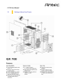
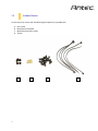
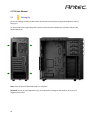
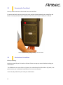
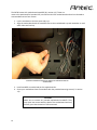
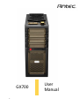
GX700 1 User Manual GX700 User Manual Congratulations on your purchase of the GX700! The new flagship in Antec’s GX series, the GX700 is ready to take your system to the next level. Builders can now assemble and expand faster with tool-less drive bays and customizable HDD trays. This boldly designed gaming enclosure features metal clasps and rugged drive bay covers. It accommodates GPUs up to 11.5” and integrates a unique flip access fan controller situated next to easy access USB 3.0 and USB 2.0 connectors. Users can cool their systems with two140 mm top fans capable of mounting 240 mm cooling radiators and easily upgrade with the enclosure’s five 3.5” tool-less HDD trays, each with SSD/HDD mounts. The GX700 does not include a power supply. Make sure you choose a power supply that is compatible with your computer components and has a long enough power harness to reach your motherboard and peripheral devices. We recommend our High Current Gamer, High Current Pro or Earthwatts power supplies for the latest ATX specification compliance, broad compatibility, and power savings capability. At Antec, we continually refine and improve our products to ensure the highest quality. As such, your new chassis may differ slightly from the description in this manual due to improvements applied for the optimal building experience. As of the date of publication, all features, descriptions, and illustrations in this manual are correct. Disclaimer This manual is intended only as a guide for Antec’s computer enclosures. For more comprehensive instructions on installing the motherboard and peripherals, please refer to the manuals that come with those components. 2 Table of Contents Section 1: Introduction 1.1 1.2 1.3 1.4 Getting to Know Your Chassis ............................................................................5 Chassis Specifications.........................................................................................6 Included Screws .................................................................................................6 Before You Begin................................................................................................7 Section 2: Hardware Installation 2.1 2.2 2.3 2.4 2.5 2.6 2.7 2.8 Setting Up ..........................................................................................................10 Removing the Front Bezel………………………………………………………………………………11 Motherboard Installation...................................................................................11 Power Supply Installation ..................................................................................13 External 5.25” Device Installation ......................................................................14 Internal 3.5” Device Installation ........................................................................16 Internal 2.5” Device Installation ........................................................................17 Cable Management ............................................................................................18 Section 3: Cooling System 3.1 3.2 3.3 3 Included Fans .....................................................................................................20 Optional Fans .....................................................................................................21 Air Filters ............................................................................................................22 Section 1 Introduction 4 GX700 User Manual 1.1 5 Getting to Know Your Chassis 1.2 Chassis Specifications Chassis Type Chassis Color Dimensions Weight Cooling Mid-Tower Military Green / Black 19.7” (H) x 7.9” (W) x 17.7” (D) 500 mm (H) x 200 mm (W) x 450 mm (D) 13.8 lbs / 6.26 kg Includes 2 x 140 mm top fans Capable of mounting 240mm radiator for water cooling Includes 1 x 120 mm rear fan Optional 2 x 120 mm front intake fans Optional 120 mm side fan mount to cool graphic cards Drive Bays 3+1 x 5.25”external tool-less drive bays Click-on 5.25” drive bay clasps Top bay designed for controls 5 x 3.5” internal tool-less HDD tray each with 2.5” SSD/HDD mount Expansion Slots 7 x PCI-E with thumbscrew access: supports NVIDIA® SLI® / AMD CrossFireX™ Motherboard Size Top I/O Panel Standard ATX, microATX, Mini-ITX 2 x USB 3.0 2x USB 2.0 Audio In/Out Fan controller - Power and Reset buttons located at the front of the chassis *The top dive bay of the GX700 is only meant for controls 6 1.3 Included Screws An inventory of all screws and intended usage and quantity is provided here: A. B. C. D. PSU screws Motherboard standoffs Motherboard and fan screws Zip ties A 7 B C D 1.4 Before You Begin In order to ensure that your building experience with the GX700 will be a positive one, please take note of the following: 8 While working inside your GX700, keep your chassis on a flat, stable surface. Make sure your build environment is clean, well-lit, and free of dust. Antec chassis feature rounded edges that minimize the occurrence of hand injuries. Nonetheless, exercise caution and control when handling chassis interiors. We strongly recommend taking the appropriate time and care when working inside the chassis. Avoid hurried or careless motions. Handle components and cards with care. Do not touch the unshielded components or contacts on a card. Hold a card by its edges. Hold a component such as a processor by its edges, never by its pins. To avoid electrostatic discharge, ground yourself periodically by touching an unpainted metal surface (such as a connector or screw on the back of this computer) or by using a wrist grounding strap. Before you connect a cable, ensure that both connectors are correctly aligned and oriented. Bent pins can be difficult to fix and may require replacement of the entire connector. This manual is not designed to cover CPU, RAM, or expansion card installation. Please consult your motherboard manual for specific mounting instructions and troubleshooting. Before proceeding, check the manual for your CPU cooler to find out if there are steps you must take before installing the motherboard. Do not sit on your chassis. Although it is constructed of heavy-duty steel and internally reinforced, it is not designed to support the weight of an adult, and may buckle. Remember to use the right tools for each task. Do not use improvised screwdrivers like coins, nails or knife blades as they may result in damage to screw threads or even injury. Do not use your fingernails to separate edges or lift the sides of the chassis, as paint chipping or injury may occur. Section 2 Hardware Installation 9 GX700 User Manual 2.1 Setting Up Put the case upright on a flat, stable surface so that the rear panel (power supply and expansion slots) is facing you. To remove the left and right side panels, remove each of the two thumbscrews, and then slide the side panel towards you. Note: Place the panel thumbscrews aside in a safe place. CAUTION: Do not use your fingernails to pry or lift the panels. Damage to the panels or injury to your fingernails may result. 10 2.2 Removing the Front Bezel You may need to remove the front bezel in order to install fans. To remove the bezel, place your hand in the notch and pull the bezel towards you, starting from the bottom. You may encounter some resistance the first time you remove the bezel; this is normal. Remove the front bezel by pulling it toward you from the bottom. 2.3 Motherboard Installation Before proceeding: Check the manual of your CPU cooler to find out if there are steps you must do before installing the motherboard. The GX700 does not come include an I/O panel. Your motherboard should include an I/O panel, if not please contact your motherboard manufacturer for the correct I/O panel. *Insert the I/O panel before you install your motherboard. 11 The GX700 comes with motherboard standoffs (B in section 1.3). These are meant to be positioned for Standard ATX, microATX or Mini-ITX motherboards and can be relocated to accommodate various form factors. 1. Lay the case down so that the open side is up. 2. Align the motherboard with the standoff holes on the motherboard tray and remember or mark which holes are lined up. Install the motherboard standoffs by aligning the motherboard with the standoff holes. 3. Install standoffs as needed and put the motherboard in. 4. Screw your motherboard into the standoffs with the provided mounting screws (C in section 1.3). CAUTION Make sure to remove any unused motherboard standoffs. They may come into contact with the back of the motherboard and may electrify your chassis exterior if left connected. 12 2.4 Power Supply Installation 1. With the case upright, place the power supply in the case and align the rear of the unit with the mounting holes. 2. Attach the power supply to the case with the screws provided (A). Attach the power supply with the provided screws 13 2.5 External 5.25” Device Installation 1. Remove the metal drive bay cover by unlocking the click-on clasps Remove the metal drive bay cover 2. Pull out the drive bay tabs on either side by twisting the locking mechanism to the vertical position 14 Pull out the drive bay tab on both sides 3. Slide your 5.25” drive through the front of the chassis until it lines up flush with the front bezel. Slide you drive in until it is flush with the bezel 4. Replace the drive bay tab the by aligning its pins with the holes on your 5.25” drive, then lock it into place by turning the locking mechanism to the horizontal position. Align and lock the drive bay tab on either side 15 2.6 Internal 3.5” Device Installation The GX700 includes 5 drive holders. You will need one for each 3.5” drive. 1. Insert three pins on the drive holder into three holes on the side of your 3.5” drive. 2. Slightly bend the drive holder to snap the drive into place. Slightly bend the drive holder to snap the drive into place 3. Pinch the ends of the drive holder together and slide the drive into the 3.5” bay until it locks into position. 16 2.7 Internal 2.5” Device Installation Each of the five 3.5” drive bays also support 2.5” drives: 1. Align your 2.5” drive with the holes of the drive holder 2. Secure your drive with the 2.5” screws provided (C in Section 1.3) 3. Slide the drive holder back into the drive rails Align and secure the 2.5” drive onto the drive holder 17 2.8 Cable Management There is a cable management compartment between the motherboard and right side panel, as well as cable ties located on the back of the motherboard panel. You can tuck excess cables in this compartment or route them to the drive bays. Choose the cables you would like to pass through the holes behind the motherboard tray. Pull them through the hole toward the right side of the case. Use the cable ties provided to hold your cables in place. Cable ties can be anchored to tiedown locations on the back of the motherboard panel. For cables which will be routed back to front drives or other internal accessories, feed the cables back through the insertion point nearest the destination of the cable. Connect the cable and then pull the slack back to the right side of the case. Use the grommet-lined cable routing holes to route PSU cables. For cables which will be routed directly to front drives or other internal accessories, cable tiedowns are located along the drive cage. Bundle front drives’ or other internal accessories’ cables together and secure them using tiedowns. 18 Section 3 Cooling System 19 GX700 User Manual 3.1 Included Fans The GX700 comes with two standard 140 mm fans and a rear 120 mm fan (yellow outline). The red rectangles indicate additional fan mounts. Mounting procedures for these fans are discussed in Section 3.2. 20 3.2 Optional Fans The GX700 includes mounts for up to three more fans. These mounts are as follows: - Optional 2 x 120 mm front intake fans - Optional 1 x 120 mm side fan to cool graphic cards Front intake 120 mm fans You can install these fans using the screws provided (C in Section 1.3). First, be sure to remove the front bezel as outlined in Section 2.2. 1. Slide the fan between the front panel and the 3.5” drive bays. Align the fan with the screw holes and screw in the fan (C in Section 1.3). Slide the fan behind the front plate 2. Screw in the second fan below. Align both fans and screw them in 21 Side 120 mm fans On the side panel, there is one mount for a 120 mm intake fan. 1. Align your fan with the screw holes. The fan should be installed with air blowing into the case. 2. Screw in the fan screws (C in Section 1.3) Screw the side fan into place by aligning it and screwing it in 3.3 Air Filters There are two filters in the GX700 that can be removed and cleaned: the front filter and the PSU intake filter. You can access the front filter by removing the metal filter panel and pushing down on the tabs at the top of the filter. 22 To remove the front air filter: 1. Remove the four thumbscrews and metal filter panel Remove four thumbscrews Remove the metal panel 2. Push down on the tab on the filter and pull it away from the inside of the bezel. Push down on the filter tab before attempting to pull it away. 23 The GX700 features a removable PSU filter. To remove the PSU filter: Remove the filter by pulling the tab toward you using the tab outside the chassis. Pull the filter toward you using the tab outside the chassis. 24 Antec, Inc. 47900 Fremont Blvd. Fremont, CA94538 tel: 510-770-1200 fax: 510-770-1288 Antec Europe B.V. Stuttgartstraat 12 3047 AS Rotterdam The Netherlands tel: +31-(0) 10-462-2060 fax: +31 (0) 10 437-1752 Technical Support US &Canada www.antec.com 1-800-22ANTEC (US) [email protected] Europe +31-(0)10-4622060 (EU) [email protected] +886 (0)800-060-696 [email protected] © Copyright 2013 Antec, Inc. All rights reserved. All trademarks are the property of their respective owners. Reproduction in whole or in part without written permission is prohibited. 25