1
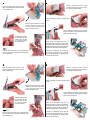
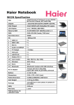
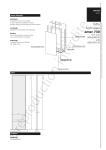
1
VID-AT1-V06 Installation Guide
v 1.0
NOTE: The VID-AT1-V06 is designed for ATI Radeon-based X800 Pro and X800
XT cards. The video card should be removed from the chassis in order to install
this cooling device.
!
2
Remove the top heat sink and unplug the
fan connection. Wipe off the original thermal
paste from the video chipset, RAM modules,
and heat sink.
CAUTION: Removal of the original heat sink my void your manufacturer’s hardware warranty. Please consult the manufacturer if unsure,
and keep all original parts in case of a return/RMA.
Apply fresh thermal paste to the main
chipset, taking care only to coat the raised
center core. The outer portion of the chipset
and metal frame do not require thermal
compound.
Most ATI Radeon X800 Pro and XT cards are
disassembled the same way, although your
specific model may vary.
Apply a small amount of thermal paste to all
4 memory chips on top of the card. Memory
on the card’s rear side will not need thermal
paste for the VID-AT1-V06.
The mounting screws on the bottom side should be
removed first. There may be 3 or more of these on
your Radeon card.
Spread the thermal compound evenly to cover
each chip using the paste packet, or a piece of
thick paper (such as a business card).
1
VID-AT1-V06 Installation Guide
v 1.0
NOTE: The VID-AT1-V06 is designed for ATI Radeon-based X800 Pro and X800
XT cards. The video card should be removed from the chassis in order to install
this cooling device.
!
2
Remove the top heat sink and unplug the
fan connection. Wipe off the original thermal
paste from the video chipset, RAM modules,
and heat sink.
CAUTION: Removal of the original heat sink my void your manufacturer’s hardware warranty. Please consult the manufacturer if unsure,
and keep all original parts in case of a return/RMA.
Most ATI Radeon X800 Pro and XT cards are
disassembled the same way, although your
specific model may vary.
The mounting screws on the bottom side should be
removed first. There may be 3 or more of these on
your Radeon card.
Apply fresh thermal paste to the main
chipset, taking care only to coat the raised
center core. The outer portion of the chipset
and metal frame do not require thermal
compound.
Apply a small amount of thermal paste to all
4 memory chips on top of the card. Memory
on the card’s rear side will not need thermal
paste for the VID-AT1-V06.
Spread the thermal compound evenly to cover
each chip using the paste packet, or a piece of
thick paper (such as a business card).
3
4
Fold the enclosure closed. The long
screws should fit through both holes in
the VID-AT1-V06 back plate.
Open the VID-AT1-V06 enclosure and
remove the protective film from the bottom
of the chipset cooler.
Finally, hand-tighten a nut firmly to both primary
screws.
Place the video card into the cooling
enclosure. There are 2 long screws
on the enclosure which must be
inserted through the card.
When installing your Radeon card, the power
supply connection can be inserted through the
back of the VID-AT1-V06.
4 small mounting screws
are included with the
VID-AT1-V06. Thread
an insulating washer
onto each of these.
From the card’s back side, insert and tighten each
of the 4 screws into the remaining mounting holes
with a screw driver.
3
NOTE: Video card RAM chips are not
perfectly flat with one another. To make sure
your liquid cooler is making the best contact
possible for your card, remove the cooler and
examine the distribution of thermal paste.
A missing or inadequate “spot” might be
corrected by further tightening a mounting
nut or screw (gradually), or applying more
thermal paste to the chip.
4
Fold the enclosure closed. The long
screws should fit through both holes in
the VID-AT1-V06 back plate.
Open the VID-AT1-V06 enclosure and
remove the protective film from the bottom
of the chipset cooler.
Finally, hand-tighten a nut firmly to both primary
screws.
Place the video card into the cooling
enclosure. There are 2 long screws
on the enclosure which must be
inserted through the card.
When installing your Radeon card, the power
supply connection can be inserted through the
back of the VID-AT1-V06.
4 small mounting screws
are included with the
VID-AT1-V06. Thread
an insulating washer
onto each of these.
From the card’s back side, insert and tighten each
of the 4 screws into the remaining mounting holes
with a screw driver.
NOTE: Video card RAM chips are not
perfectly flat with one another. To make sure
your liquid cooler is making the best contact
possible for your card, remove the cooler and
examine the distribution of thermal paste.
A missing or inadequate “spot” might be
corrected by further tightening a mounting
nut or screw (gradually), or applying more
thermal paste to the chip.