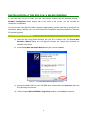
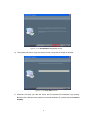
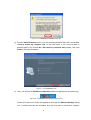
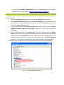
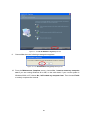
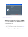
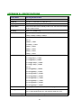
1
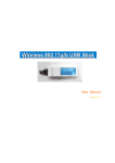
802.11b/g WLAN Cardbus Adapter
User Manual
Version 1.1
M090403V11
No part of this documentation may be reproduced in any form or by any means or used to make any
derivative work (such as translation, transformation, or adaptation) without written permission from
the copyright owner.
All the other trademarks and registered trademarks are the property of their respective owners.
Statement of Conditions
We may make improvements or changes in the product described in this documentation at any time. The
information regarding to the product in this manual are subject to change without notice.
We assume no responsibility for errors contained herein or for direct, indirect, special, incidental, or
consequential damages with the furnishing, performance, or use of this manual or equipment supplied with it,
even if the suppliers have been advised of the possibility of such damages.
Electronic Emission Notices
This device complies with Part 15 of the FCC Rules. Operation is subject to the following two conditions:
(1) This device may not cause harmful interference.
(2) This device must accept any interference received, including interference that may cause undesired
operation.
FCC INFORMATION
The Federal Communication Commission Radio Frequency Interference Statement includes the following
paragraph:
The equipment has been tested and found to comply with the limits for a Class B Digital Device, pursuant to
part 15 of the FCC Rules. These limits are designed to provide reasonable protection against harmful
interference in a residential installation. This equipment generates, uses and can radiate radio frequency
energy and, if not installed and used in accordance with the instruction, may cause harmful interference to
radio communication. However, there is no guarantee that interference will not occur in a particular installation.
If this equipment does cause harmful interference to radio or television reception, which can be determined by
turning the equipment off and on, the user is encouraged to try to overcome the interference by one or more of
the following measures:
--Reorient or relocate the receiving antenna.
--Increase the separation between the equipment and receiver.
--Connect the equipment into an outlet on a circuit different from that to which the receiver is connected.
--Consult the dealer or an experienced radio/TV technician for help.
The equipment is for home or office use.
R&TTE Compliance Statement
This equipment complies with all the requirements of the Directive 1999/5/EC of the European parliament and
the council of 9 March 1999 on radio equipment and telecommunication terminal Equipment and the mutual
recognition of their conformity(R&TTE).
The R&TTE Directive repeals and replaces in the directive 98/13/EEC. As of April 8, 2000.
IMPORTANT NOTE
FCC RF Radiation Exposure Statement: This equipment complies with FCC RF radiation exposure limits set
forth for an uncontrolled environment. This device has been tested for compliance with FCC RF Exposure
(SAR) limits in typical laptop configurations, and this transmitter must not be co-located or operating in
conjunction with any other antenna or transmitter.
Caution: Changes or modifications not expressly approved by the party responsible for compliance could void
the user's authority to operate the equipment.
M090403V11
Table of Contents
INTRODUCTION .............................................................................................................................................1
1.1 FEATURES .............................................................................................................................................1
1.2 PRODUCT PACKAGE ...........................................................................................................................1
1.3 SYSTEM REQUIREMENTS..................................................................................................................1
INSTALLATION OF THE 802.11b/g WLAN CARDBUS............................................................................3
2.1 INSTALLATION PROCEDURES..........................................................................................................3
2.2 VERIFYING A SUCCESSFUL INSTALLATION .................................................................................6
WLAN-G CONFIGURATION TOOL BASICS ............................................................................................7
3.1 RIGHT-CLICK MENU OF THE TRAY ICON ......................................................................................7
Wireless Radio On ..............................................................................................7
Wireless Radio Off..............................................................................................7
Remove Status Icon ...........................................................................................7
Wireless Network Status .....................................................................................8
Advanced Configuration ......................................................................................8
WEP Encryption .................................................................................................8
IBSS Channel ....................................................................................................8
Country/Domain ................................................................................................8
Version Information ...........................................................................................8
3.2 PROGRAM CONTROLS .......................................................................................................................9
The
The
The
The
The
The
The
Status Tab ..................................................................................................9
Configuration Tab ...................................................................................... 11
Encryption Tab .......................................................................................... 12
Site Survey Tab ......................................................................................... 14
IBSS Tab .................................................................................................. 14
Domain Tab .............................................................................................. 15
About Tab................................................................................................. 16
APPENDIX A: TROUBLESHOOTING .......................................................................................................18
DISABLE 802.11b/g WLAN CARDBUS...................................................................................................18
UNINSTALL WLAN-G CONFIGURATION TOOL AND THE CARD’S DRIVER................................18
802.11b/g WLAN CARDBUS DOES NOT WORK PROPERLY..............................................................21
APPENDIX B: SPECIFICATIONS...............................................................................................................22
M090403V11
Table of Figures
FIGURE 2-1: THE FOUND NEW HARDWARE WIZARD DIALOG BOX .................................................................3
FIGURE 2-2: THE WLAN IEEE802.11b/g SETUP WINDOW .......................................................................................4
FIGURE 2-3: THE SETUP STATUS SCREEN .................................................................................................................4
FIGURE 2-4: THE HARDWARE INSTALLATION DIALOG BOX..............................................................................5
FIGURE 2-5: THE COMPLETE SCREEN.......................................................................................................................5
FIGURE 2-6: THE WLAN-G CONFIGURATION TOOL TRAY ICON........................................................................5
FIGURE 2-7: THE DEVICE MANAGER DIALOG BOX...............................................................................................6
FIGURE 3-1: RIGHT-CLICK MENU OF THE TRAY ICON ............................................................................................7
FIGURE 3-2: THE REMOVE WIRELESS STATUS ICON DIALOG BOX .................................................................8
FIGURE 3-3: THE WIRELESS SETTINGS DIALOG BOX...........................................................................................9
FIGURE 3-4: THE STATUS TAB ....................................................................................................................................10
FIGURE 3-5: THE CONFIGURATION TAB.................................................................................................................11
FIGURE 3-6: THE ENCRYPTION TAB.........................................................................................................................13
FIGURE 3-7: THE SITE SURVEY TAB .........................................................................................................................14
FIGURE 3-8: THE IBSS TAB...........................................................................................................................................15
FIGURE 3-9: THE DOMAIN TAB ..................................................................................................................................16
FIGURE 3-10: THE ABOUT TAB ...................................................................................................................................17
FIGURE 4-1: THE DEVICE MANAGER DIALOG BOX.............................................................................................18
FIGURE 4-2: THE CONFIRM DEVICE REMOVAL MESSAGE BOX ......................................................................19
FIGURE 4-3: THE ADD OR REMOVE PROGRAMS DIALOG BOX........................................................................19
FIGURE 4-4: THE WLAN IEEE802.11b/g SETUP WINDOW .....................................................................................20
FIGURE 4-5: THE WLAN IEEE802.11b/g SETUP MESSAGE BOX ..........................................................................20
FIGURE 4-6: THE MAINTENANCE COMPLETE SCREEN .....................................................................................21
M090403V11
INTRODUCTION
Being five times faster than the speed of 802.11b network standard devices, the innovative 802.11g
standard lets the wireless network become incredibly easier and faster (up to 54Mbps) than ever.
Your 802.11b/g WLAN Cardbus surely will bring you into such a high-speed network sphere. This
document describes how to install your 802.11b/g WLAN Cardbus, which aims to let your computer
communicate with 802.11 networks quickly and seamlessly. Wireless LAN is local area networking
without wires, which uses radio frequencies to transmit and receive data between PCs or other
network devices. Additionally, wireless LAN is able to configure either independent networks, which
is also known as peer-to-peer or ad-hoc network, or infrastructure networks. The former is suitable
for small or temporary peer-to-peer configurations, and the later is offering fully distributed data
connectivity via micro cells and roaming.
To obtain most benefits your 802.11b/g WLAN Cardbus brings, please read this manual carefully
before using it.
1.1 Features
With 802.11b/g WLAN Cardbus, you can:
establish a wireless connection without the hassles and cost of cabling
operate Ad-Hoc or Infrastructure mode
utilize up to 128-bit WEP encryption
enjoy high-speed data transfer rate up to 54 Mbps
employ automatic data rate switching which offers maximum reliability, throughput and
connectivity
possess the network’s range up to 100 meters indoor and 400 meters outdoor
monitor and configure the network via the supplied friendly-interfaced application –
WLAN-G Configuration Tool
1.2 Product Package
Before starting the installation, please make sure the package you purchased includes the following
items:
One 802.11b/g WLAN Cardbus.
One Setup Wizard CD with User Manual
One Quick Installation Guide
If any of the items above is missing or damaged, please contact your distributor.
1.3 System Requirements
To properly operate your Card, your computer should meet the following minimum requirements:
Microsoft Windows 98/98 Second Edition/ME/2000 or Windows XP
1
Minimum 5 Mbytes free disk space for installing the driver and the utility program
32 MB RAM or above
A CD-ROM drive
300 MHz processor or higher
Cardbus interface
2
INSTALLATION of THE 802.11b/g WLAN CARDBUS
It’s free and easy for you to install your 802.11b/g WLAN Cardbus and the attached program –
WLAN-G Configuration Tool. Simply with a few clicks of the mouse, you will succeed the
completion of installation.
To have the 802.11b/g WLAN Cardbus operated appropriately, please read and go along with the
instructions below carefully. Here, we will illustrate the installation instructions based on Windows
XP operating system.
2.1 Installation Procedures
a) Insert the 802.11b/g WLAN Cardbus into your PC’s Cardbus slot. The Found New
Hardware Wizard dialog box will appear because the system has detected the
insertion of the Card.
b) In the Found New Hardware Wizard dialog box, choose Cancel.
Figure 2-1: The Found New Hardware Wizard Dialog Box
c) Insert the supplied CD into your CD-ROM drive, and double-click setup.exe under the
CD’s directory to execute it.
d) In the prompted WLAN IEEE802.11b/g Setup window, choose Next to continue.
3
Figure 2-2: The WLAN IEEE802.11b/g Setup Window
e) The system will start to copy the drivers found. It may take a couple of minutes.
Figure 2-3: The Setup Status Screen
f)
Windows will notify you that the driver has not passed the Windows Logo testing.
Because the Card has been tested to work with Windows XP, please choose Continue
Anyway.
4
Figure 2-4: The Hardware Installation Dialog Box
g) From the Install Finished screen, if you are operating Windows 98 or ME, choose Yes,
I want to restart my computer now; on the other hand, if your current system is
Windows 2000 or XP, choose No, I will restart my computer later instead. Then click
Finish to finish the installation.
Figure 2-5: The Complete Screen
h) Then, you will find the WLAN-G Configuration Tool icon appeared in the system tray.
Figure 2-6: The WLAN-G Configuration Tool Tray Icon
Double-click the icon to launch the application and open the Wireless Settings dialog
box, in which seven tabs are contained. Now you may start to monitor and configure
5
the network via WLAN-G Configuration Tool. For more details about the program,
please refer to the next chapter -- WLAN-G Configuration Tool Basics.
2.2 Verifying a Successful Installation
To confirm that your 802.11b/g WLAN Cardbus is properly installed, please go along with the
procedures below.
1.
Right-click the My Computer desktop icon and choose Properties from its menu.
2.
In the System Properties dialog box, choose Device Manager if you are under Windows
98 or ME. If you are operating Windows 2000 or XP, click the Hardware tab, and then
choose the Device Manager button.
3.
In the opened window, expand Network adapters to find the input device – WLAN-G
FRISBEE Wireless LAN 802.11b/g Adapter. Right-click over the item and choose
Properties.
4.
From the opened dialog box, on the General tab, find the descriptions under the Device
Status pane to learn if the card is working properly. However, if there’s an error message
shown, please choose Uninstall from the opened menu while right-clicking over the
Cardbus item, to which a red or yellow icon is attached beside, in the Device Manager
dialog box. Then restart your system and go through the installation procedures again.
The following picture indicates a successful installation of the 802.11b/g WLAN Cardbus.
Figure 2-7: The Device Manager Dialog Box
6
WLAN-G CONFIGURATION TOOL BASICS
Once you insert your 802.11b/g WLAN Cardbus, it will operate with the factory default settings.
However, you may configure the desired settings by double-clicking the WLAN-G Configuration
Tool icon,
, on the system tray. In the prompted Wireless Settings dialog box, there are seven
tabs, including Status, Configuration, Encryption, Site Survey, IBSS, Domain, and About, and
each proffers various functions to assist you in configuring the connection to the networks.
This chapter is divided into the two sections: Right-Click Menu of the Tray Icon and Program
Controls. Please refer to the preferred topic to obtain more information and enjoy vast advantages
WLAN-G Configuration Tool brings.
3.1 Right-Click Menu of the Tray Icon
Right-clicking the WLAN-G Configuration Tool icon in the system tray will open a menu as the
following picture:
Figure 3-1: Right-Click Menu of the Tray Icon
Check the descriptions below to obtain detailed information about each command in the menu.
Wireless Radio On
Choose the Wireless Radio On command to receive the radio frequency signal.
Wireless Radio Off
Choosing the Wireless Radio Off command will stop receiving the radio frequency signal.
Remove Status Icon
If you do not wish to have the WLAN-G Configuration Tool icon displayed in the system tray,
choose this command to open the Remove Wireless Status Icon dialog box, and then choose Yes
to have the icon disappeared. The icon will reappear next time when you restart the computer. If you
intend to remove it permanently, put a tick in the checkbox next to the Remove Status Icon
Permanently option. To launch the utility hereafter, click Start on the taskbar, choose Program from
the menu, and then point to WLAN-G Configuration Tool of the submenu of WLAN-G TOOLS.
7
Clicking No will undo the removal.
Figure 3-2: The Remove Wireless Status Icon Dialog Box
Wireless Network Status
Choose this command to launch the Status tab of the Wireless Settings dialog box. For more
details about the tab, please refer to The Status Tab in the Program Controls section below.
Advanced Configuration
Choose this command to launch the Configuration tab of the Wireless Settings dialog box. Please
refer to The Configuration Tab in the Program Controls section below to gain more information
about the tab.
WEP Encryption
Choose this command to launch the Encryption tab of the Wireless Settings dialog box. This tab
offers you a number of options to maintain the secure management in a wireless LAN environment.
See the explanations in The Encryption Tab under the Program Controls section below for more
details.
IBSS Channel
Choosing this command will launch the IBSS tab of the Wireless Settings dialog box. To obtain
more information about the tab, please refer to The IBSS Tab in the Program Controls section
below.
Country/Domain
Choosing this command will launch the Domain tab of the Wireless Settings dialog box. Detailed
information about this tab is presented in The Domain Tab of the Program Controls section.
Version Information
Choosing this command will launch the About tab of the Wireless Settings dialog box. The About
tab reveals general information on your 802.11b/g WLAN Cardbus, including the release version of
driver and the WLAN-G Configuration Tool and the card’s MAC Address.
8
3.2 Program Controls
When you double-click the WLAN-G Configuration Tool tray icon, the Wireless Settings dialog
box will be prompted as the picture shown below. The application is a window-based program,
which is consisted of seven tabs, including Status, Configuration, Encryption, Site Survey, IBSS,
Domain, and About.
Figure 3-3: The Wireless Settings Dialog Box
Check the desired items below to obtain more information about these tabs.
The Status Tab
In the Wireless Settings dialog box, click the Status tab, and you will see the following display.
Here presents the status of your current connection. To close the window, click OK.
Note: Choosing the Wireless Network Status command from the right-click menu of WLAN-G
Configuration Tool tray icon will launch this tab too.
9
Figure 3-4: The Status Tab
Note: The texts before ” Wireless Settings” in the caption bar of the dialog box is the profile name of the
current connection. Thus, the caption contexts vary according to the connectivity at the given time. From
the above picture, the associated profile is named “Wireless”.
From the window, the general information on the status of currently connected entry is presented.
You may want to click the Rescan button to reinitiate the scanning process and update the status.
Later the result of scanning will be renewed and displayed in the window. If you wish to stop the
networking connection, click the Disable Radio button to stop scanning. However, if you are already
in the disabled radio mode, you will find the Enable Radio button here instead. Click Enable Radio
to regain the link then.
State
Here displays either the MAC Address of the current associated access point in the Infrastructure
mode or a BSSID from any computer joining in the Ad-Hoc network.
Current Tx Rate
This feature indicates the transmission rate of the current connection.
Current Channel
Here reveals the current channel operated in the wireless network. Note that the channel number
differs as the radio scans any available channels in the Infrastructure mode.
Throughout (bytes/sec)
This feature indicates the rates of transmitting (Tx) and receiving (Rx) data package of your
802.11b/g WLAN Cardbus within a short period of time; thus, the values vary on a time basis.
10
Link Quality
Link Quality is based on the percentage of successfully transmitted or received signal of the
associated access point beacon within a limited period. The higher the percentage, the better the
link quality. The bar graph beside also provides a visual interpretation of the current link quality. It
is noted that the Link Quality and Signal Strength features only apply to the Infrastructure mode.
They are inapplicable in the Ad-Hoc mode since data will be transferred from many different
computers.
Signal Strength
You may learn the received signal strength of the baseband processor of the beacon signal from
the Signal Strength bar beside, and it’s also presented in terms of percentage. As the signal gets
stronger, the signal percentage rate gets higher. It is noted that the Signal Strength and Link
Quality features only apply to the Infrastructure mode. They are inapplicable in the Ad-Hoc mode
since data will be transferred from many different computers.
The Configuration Tab
Click this tab to edit different profiles for different network configurations. When finish changing the
settings, please click Apply to perform the new configuration at last.
Note: Choosing the Advanced Configuration command from the right-click menu of WLAN-G
Configuration Tool tray icon will launch this tab too.
Figure 3-5: The Configuration Tab
Profile Name
Enter texts in the Profile Name field to identify a new profile. After defining the configurations
below, click the Apply button to establish the profile. To switch between any existing profiles,
11
simply click the arrow button at the right of the Profile Name field to open the pull-down menu and
then select the intended one from it.
Note: You will have at least one profile named Default. When selecting any link from the list under the Site
Survey tab, the common information on this chosen link will be illustrated under the Configuration tab.
Network Name
Network Name, also known as SSID (Service Set Identifier), must be unique to distinguish itself
as a particular wireless network, while all wireless points in this network area share the same
SSID. Type the identical SSID in the Network Name field to associate with access points or
stations within the specified wireless LAN. To change the Network Name, highlight the name in
the box, edit a new SSID, and then click Apply to save the changes.
Network Type
Two network types are offered here: Access Point and Peer-to-Peer. Choose the intended type
from the two options. The Access Point mode, which is also known as the Infrastructure mode,
allows you to communicate with a wired network via an access point. If you attempt to operate this
mode, you must indicate the identical Network Name to make a communication with the intended
access point. On the other hand, the Peer-to-Peer mode provides you with the so-called Ad-Hoc
communication, which means each wireless-equipped computers within a group is able to
connect with each other as an independent wireless LAN without the use of an access point. Each
station within this Ad-Hoc network has to define the same Network Name.
The Encryption Tab
Click the Encryption tab to define the encryption settings for a specific profile. It offers you various
options concerning the so-called WEP (Wired Equivalent Privacy) to maintain the secure
management in a wireless LAN environment. See the explanations below for more details, and
before making an activation of any new settings, click Apply. To leave the window, click OK. To
undo the new settings, select the Cancel button.
Note: Choosing the WEP Encryption command from the right-click menu of WLAN-G Configuration Tool
tray icon will launch this tab too.
12
Figure 3-6: The Encryption Tab
Encryption (WEP security)
If you choose Disabled from the pull-down list, you will have the 802.11b/g WLAN Cardbus
communicated with all stations within the same networking community without any data
encryption. Otherwise, two key lengths are offered: 64 bit and 128 bit. Specify a preferred one
from the two, so that you may use the identical WEP key to make a communication with the
chosen access point.
Create Keys Manually
Once you set the Encryption type as 64 bit or 128 bit, you may choose to edit WEP keys
manually or create them via the passphrase of your wireless network. If you choose the Create
Key Manually option, you may directly enter up to 4 WEP keys for use in WEP encryption. To
generate the WEP keys, please define the key entry method as Alphanumeric or Hexadecimal
(for hexadecimal characters, only digits 0-9 and letters A-F are valid). Then edit the texts in the
blank fields below, from Key 1 to Key 4, as the encryption codes. Note that these codes/keys
shall be identical between the wireless nodes within the range and the access point only. Check
the table below to find valid key length of each encryption type:
64 bit
Alphanumeric
5 characters
Hexadecimal
10 digits
128 bit
13 characters
26 digits
Use WEP Key
Indicate which WEP key you intend to apply to activate the WEP encryption from the pull-down
menu. Make sure that the intended access point on the wireless network shares the same keys.
13
By default, Key 1 will be used.
Create Keys with Passphrase
Choose this command when the associated wireless network uses a passphrase to create WEP
keys. Enter the passphrase string in the Passphrase filed to generate four encryption keys in the
Key fields above. Note that only letters A-F are valid for the Passphrase feature.
Note: When entering the passphrase here, ensure that you have specified an accurate type of the
Encryption (WEP security) above according to the associated agent’s configuration. Otherwise, the
inaccuracy will cause any failure of performance.
After finish configuring the Encryption features, remember to click the Apply button to initiate the
new settings.
The Site Survey Tab
First of all, while entering this tab, please do choose the Rescan button to reinitiate the scanning
process and update the list. Later the result of scanning will be renewed and displayed afterwards.
From the offered information, you may learn the general information on the status of current scan
lines, including BSSID, SSID, signal strength, the channel number, WEP type, and network type.
In addition, to directly make an association with any site on the list, double-click the intended entry,
and you will be led to the Status tab then.
Figure 3-7: The Site Survey Tab
The IBSS Tab
If you, as a creator of the wireless network, are communicating with other stations via the IBSS
(802.11 Ad-hoc) mode to form peer-to-peer networks, click the IBSS (Independent Basic Service
Set) tab to specify an operating radio frequency channel from the pull-down list under the IBSS
14
Channel Selection section.
Note: Choosing the IBSS Channel command from the right-click menu of WLAN-G Configuration Tool
tray icon will launch this tab too.
Note that the available channels differ from country to country, and the channel number must be the
same between the entries/stations within the range, so that each can communicate with each other.
Or you may simply click Defaults to automatically determine the channel number for you. When
done, click Apply to activate the new configuration.
On the other hand, while in the Access Point mode, you will find the channel number is the same
as the associated access point. Thus, there’s no need to manually set the value.
Figure 3-8: The IBSS Tab
The Domain Tab
While in the 5GHz range, the network operation may differ from country to country, or domain to
domain. This is because the 802.11d protocol was established. To have the operation normally
processed, choose the Domain tab to change relevant settings.
Note: Choosing the Country/Domain command from the right-click menu of WLAN-G Configuration Tool
tray icon will launch this tab too.
15
Figure 3-9: The Domain Tab
802.11d Support
802.11d Support lets you operate multi-country roaming. To automatically adjust regulatory
domain while operating network in different countries, choose either Strict or Flexible according
to your need. If you choose None, the task will be terminated.
Countries/Domains
Define the regulatory domain from the drop-down menu of this command according to the country
you are located in. More detailed information about the defined country/domain will be listed
below afterwards.
When you are done, remember to click Apply to let the new settings take effect.
The About Tab
This tab reveals general information on your 802.11b/g WLAN Cardbus, including the following
items:
Note: Choosing the Version Information command from the right-click menu of WLAN-G Configuration
Tool tray icon will launch this tab too.
16
Figure 3-10: The About Tab
Network Driver
Displays the current version and released date of the 802.11b/g WLAN Cardbus’ driver.
Configuration Utility
Displays the current version and released date of the WLAN-G Configuration Tool application.
NIC Firmware
Displays the current NIC card firmware version and the MAC (Media Access Control) address of
your wireless card. It is consisted of 12-digit hexadecimal numbers (48 bits in length) to identify
your computer's physical address on the local area network.
17
APPENDIX A: TROUBLESHOOTING
This section provides solutions to problems that you might encounter during the installation and
operation of your 802.11b/g WLAN Cardbus. Please refer to the desired topics below and read the
description to solve your problems.
Disable 802.11b/g WLAN Cardbus
Supposed you do not need the 802.11b/g WLAN Cardbus to establish the wireless connectivity for
any reason, you can directly unplug and remove your 802.11b/g WLAN Cardbus from the Cardbus
slot on your computer, or click Disable Radio on the Status tab of the Wireless Settings dialog
box. Once the device is removed, the connection to the network stops. Thus, be sure that you have
closed all the network applications before processing the removal.
Uninstall WLAN-G Configuration Tool and the Card’s Driver
Prior to starting uninstalling, please make sure that the utility is closed, and then go along with the
procedures below to entirely uninstall WLAN-G Configuration Tool and the card driver.
1.
Right-click the My Computer desktop icon and choose Properties from its menu.
2.
In the System Properties dialog box, choose Device Manager if you are under Windows
98 or ME. If you are operating Windows 2000 or XP, click the Hardware tab, and then
choose the Device Manager button.
3.
In the opened window, expand Network adapters to find the input device – WLAN-G
FRISBEE Wireless LAN 802.11b/g Adapter. Right-click over the item and choose
Uninstall.
Figure 4-1: The Device Manager Dialog Box
18
4.
In the Confirm Device Removal message box, click OK to proceed with the removal of
the hardware.
Figure 4-2: The Confirm Device Removal Message Box
5.
Click Start on the taskbar and choose Control Panel from the Settings menu.
6.
Select Add or Remove Programs to open the dialog box shown as below.
Figure 4-3: The Add or Remove Programs Dialog Box
7.
Click the Change/Remove button under WLAN FRISBEE IEEE802.11b/g.
8.
In the prompted WLAN IEEE802.11b/g Setup window, choose Remove and then click
the Next button to begin uninstalling the program.
19
Figure 4-4: The WLAN IEEE802.11b/g Setup Window
9.
Choose Yes when the following message box appears.
Figure 4-5: The WLAN IEEE802.11b/g Setup Message Box
10. From the Maintenance Complete screen, choose Yes, I want to restart my computer
now if you are running Windows 98 or ME; on the other hand, if your current system is
Windows 2000 or XP, choose No, I will restart my computer later. Then choose Finish
to entirely complete the removal.
20
Figure 4-6: The Maintenance Complete Screen
802.11b/g WLAN Cardbus Does Not Work Properly
If this happens, follow the guidelines below.
Unplug and replug the 802.11b/g WLAN Cardbus into your PC’s Cardbus slot.
Right-click the My Computer desktop icon and choose Properties to open the System
Properties dialog box. If you are under Windows 98 or Me, choose the Device Manager
tab, or if your system is Windows 2000 or XP, click the Hardware tab, and then choose the
Device Manager button. In the opened window, find your Cardbus to see if the installation
is successful. If you see a yellow exclamation mark beside the item, please go along with
the steps below to reinstall the drivers:
1.
Uninstall the software and hardware drivers from your PC. (Please refer to the
previous topic for details)
2.
Restart your computer and repeat the installation procedures as indicated in Chapter
2: Installation.
3.
When finished, open the Device Manager window again to verify if the installation is
approved. The yellow exclamation mark shall be removed for this time.
21
APPENDIX B: SPECIFICATIONS
Product Name
802.11b/g WLAN Cardbus
Host Interface
32-bit Cardbus
Standards
IEEE 802.11, IEEE 802.11b, IEEE 802.11g
Frequency Band
2.400 ~ 2.4835GHz (subject to local regulations)
Current Drain
Power save mode=22mA, Standby mode=7mA, Transmit mode=460mA,
Receive mode=410mA
Spreading
DSSS (11b), OFDM (11g)
Data Rate
1Mpbs, 2Mbps, 5.5Mbps, 6Mbps, 9Mbps, 11Mbps, 12Mbps, 18Mbps,
24Mbps, 36Mbps, 48Mbps, 54Mbps
Transmit Power
802.11b≧17dBm
802.11g
6/9Mbps≧17dBm
12/18Mbps≧15dBm
24Mbps≧14dBm
36Mbps≧14dBm
48Mbps≧12dBm
54Mbps≧12dBm
Receive Sensitivity
802.11b
8% FER@1Mbps≦-91dBm
8% FER@2Mbps≦-88dBm
8% [email protected]≦-85dBm
8% FER@11Mbps≦-83dBm
802.11g
10% PER@6Mbps≦-88dBm
10% PER@9Mbps≦-87dBm
10% PER@12Mbps≦-84dBm
10% PER@18Mbps≦-82dBm
10% PER@24Mbps≦-79dBm
10% PER@36Mbps≦-75dBm
10% PER@48Mbps≦-69dBm
10% PER@54Mbps≦-68dBm
Modulation
CCK (11b), BPSK, QPSK, 16-QAM, 64-QAM (11g)
Security
64/128 bit WEP Encryption
802.1x, WPA (Windows XP SP1 and Windows 2000 SP4 only)
Internal Antenna Type
Dual Antenna Diversity Switching
22
Media Access Control
RF activity
Supplied Driver
CSMA/CA with ACK
Warranty
1 year
Temperature Range
0~65°C (Operating)
Humidity
Max. 95% Non-condensing
Operating Range
Open Space: up to 400meters; Indoor: up to 100meters
The transmission speed varies in the surrounding environment.
CIS
Customer Defined
23