1
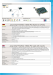
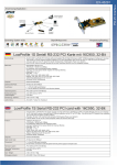
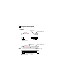
11 Physical Description
(1) Panel
Power LED
1000/100/10Mbps LED
LED Panel
Speed
5-Port Gigabit Switch
POWER LNK/ACT
1
2
3
4
5-Port
5
Link/Activity LED
RJ45 Connectors
Power Connector
Power LED
1000/100/10Mbps LED
LED Panel
Speed
8-Port Gigabit Switch
POWER LNK/ACT
1
2
3
4
8-Port
5
6
7
8
Link/Activity LED
RJ45 Connectors
Power Connector
Figure 1-1 Panel description
(2) LED
5/8 Port Gigabit Switch
LED
PWR
(Power)
LNK/ACT
(Link/Activity)
SPEED
(10/100/1000M)
Color
Status
Description
Lit
Power is supplied
Green
Green
Off
No power
Lit
A valid link is established
Flash
Data packets received
Off
No link is established
Off
This port runs at 10Mbps
Yellow
This port runs at 100Mbps
Green
This port runs at 1000Mbps
Table 1-1 LED description
22 Installation
1. Operating Environment
This switching hub must be installed and operated within the limits
of specified operating temperature (32-1310F) and humidity (1095% Noncondensing). Do not place objects on top of the unit. Do
not obstruct any vents at the sides of the unit. Do not position the
unit near any heating source such as heater, radiator, or direct
exposure to sun. Prevent entering of water and moisture into the
unit. If necessary, use dehumidifier to reduce humidity.
2. Connecting to network devices
The RJ-45 ports on the switch support Auto-MDI/MDI-X function
which allows using straight-through or cross-over type cables to
connect this switch to workstation or hub.
Connect one end of the network cable to the RJ-45 port on the
rear panel, and connect the other end of the network cable to the
RJ-45 port on the network device. Follow the same procedure to
connect all the RJ-45 ports of the switch. The UTP network cables
must comply with EIA/TIA 568 specifications and Category 5
standard for 1000Mbps data transmission. Maximum length,
using UTP cable, between the switch and connected device is 100
meters (300ft). Once the network cable is connected to both ends
and the attached network device is powered on, the green
LNK/ACT LED should be lit.
External Power Adapter
3. Connecting the power
AC Power
Connect the output end of the power
adapter to the power connector on the
rear panel of the unit. Connect the
power adapter to the power outlet. Figure 2-1
The green Power LED on the front
panel should be lit.
Connect the power adapter
33 Trouble-shooting
1. Power LED is not lit
z Check if the power cord is properly connected to the external power
adapter and the power outlet. Make sure the power jack is firmly
plugged into the power socket of the switch.
2. Link/Activity is not lit when connect to 1000/100Mbps device
z Check the power switch of the network device attached to the switch;
make sure it is turned ON.
z Check the network cable; make sure it is properly connected to the
switch and the network device.
z Check the network cable; make sure the UTP cables comply with
EIA/TIA 568 and Category 5 specification.
[!] Contact your dealer if problem persist.