1
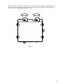
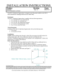
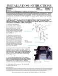
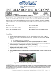
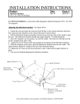
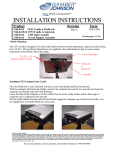
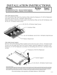
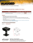
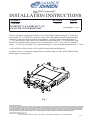
INSTALLATION INSTRUCTIONS
Product
Revision
7120-0587
Form
INST-577
Rev.A
NOTEPADTMV & NOTEPADTMV-LT
CAM CLIP CONVERSION KIT
Printing Spec: PS-001
This kit contains the components needed to convert the Gamber Johnson Notepad V (7160-0250)
and Notepad V-LT (7160-0402) so that they can be used with smaller notebook and tablet format
computers, without the bulk of the Rear Support/Brace. The kit provides a depth adjustment of
7.2 - 8.1 inch when the Cam Mount Clip is installed facing inward and 8.1 - 9 inch when the Cam
Mount Clip is installed facing outward. The width adjustment, 10.62 - 16.50 inch (for Notepad V)
and 8.2 - 11.8 inch (for Notepad V-LT) remain unchanged. As does the height adjustment of 0 - 1.5 inch.
A 9/64 inch Hex (Allen) wrench will be needed for installation and adjustment.
If attached, remove existing Rear Support/Braces from back edge of cradle. When finished cradle
should appear as shown in Fig. 1.
Fig. 1
Product Mounting Disclaimer
Gamber-Johnson is not liable under any theory of contract or tort law for any loss, damage, personal injury, special, incidental or consequential damages for personal injury or other damage
of any nature arising directly or indirectly as a result of the improper installation or use of its products in vehicle or any other application. In order to safely install and use Gamber-Johnson
products full consideration of vehicle occupants, vehicle systems (i.e., the location of fuel lines, brakes lines, electrical, drive train or other systems), air-bags and other safety equipment is
required. Gamber-Johnson specifically disclaims any responsibility for the improper use or installation of its products not consistent with the original vehicle manufactures specifications
and recommendations, Gamber-Johnson product instruction sheets, or workmanship standards as endorsed through the Gamber-Johnson Certified Installer Program.
If you need assistance or have questions, call Gamber-Johnson at 1-800-456-6868
1/4
ASSEMBLY
Install components of conversion kit as shown in Fig. 2. Position Cam Mount Clips facing inward
(shown) or outward based on depth adjustment range (see page 1) needed for computer/tablet.When
completed cradle should appear as shown in Fig. 3. All screws should be loosely tightened to allow
side-to-side movement of Clip Guides and rotation of Cam Clips.
#8 x .625 SHCS
Qty. 2
Cam Clip
Qty. 2
5/16 External Tooth Lock
Washer, Qty. 2
Cam Mount Clip
Qty. 2
Clip Guide
Qty. 2
#8 Flat Washer
Qty. 4
#8-32 x 0.5 SHCS
Fig. 2
Spacer
#8-32 x 1 SHCS
Fig. 3
2/4
ADJUSTMENT
If latch on the cradle is locked use key provided to unlock. Pull the lock side of the
cradle away from the fixed side to width needed to place computer/tablet on top of cradle.
Fig. 4
Loosen adjustment screws securing Front and Side Clips enough to raise them and move them
in their slots.
Place the computer/tablet on the cradle. Slide the computer/tablet tight against the Front Clips.
Keeping computer/tablet in contact with Front Clips slide it to make contact with Side Clips
mounted on fixed side of cradle. Push lock side of cradle towards the fixed side until the Side
Clips make contact with the computer//tablet. Turn the latch to secure computer/tablet in cradle.
Make sure tabs on Side Clips are above computer/tablet. Fig. 5
Adjust Front Clips side-to-side. When in desired position secure by tightening adjustment screw.
Adjust Side Clips side-to-side and up-down. When in desired position secure by tightening
adjustment screw.
Do not position Clips over vents or desired ports.
Fig. 4
Adjustment Screw
10 Places
Fig. 5
3/4
Slide Clip Guides side-to-side. When in desired position secure by tightening adjustment screw.
Rotate Cam Clip until making contact with computer/tablet. When making contact in desired
location secure by tightening adjustment screw.
Fig. 6
4/4