1
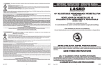
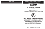
To reduce the risk of electrical shock and fire please observe the following instructions:
- Always unplug the cord before moving, servicing or cleaning.
- NEVER place the Fan in or near water.
- Disassembled grills may be immersed to be cleaned with a mild detergent and water.Wipe all other parts with soft cloth moistened with water and mild detergent
only. DRY ALL PARTS COMPLETELY BEFORE REASSEMBLING. After any maintenance or servicing, completely reassemble unit as described in this instruction
manual before reconnecting to the power supply.
- NEVER use ALCOHOL or SOLVENTS such as gasoline, benzene, paint thinner, or other harsh cleaners.
IMPORTANT INSTRUCTIONS - OPERATING MANUAL
INSTRUCCIONES IMPORTANTES - MANUAL DE OPERACIÓN
SERVICING: For servicing, other than general user maintenance, please contact Customer Service at 800-233-0268, Monday through Friday, from 8am-5pm Eastern.
STORAGE: Store the Fan with these instructions, in the original carton in a cool, dry place.
LUBRICATION: Motor is permanently lubricated.
 LASKO PRODUCTS, INC. LIMITED WARRANTY (Valid in the USA, its Territories, and CANADA Only)
WHAT THIS WARRANTY COVERS:  This product is warranted against defects in workmanship and/or materials.
HOW LONG THIS WARRANTY LASTS:  This warranty extends only to the original purchaser of the product and lasts for one (1) year from the date of original purchase or
until the original purchaser of the product sells or transfers the product, whichever first occurs.
WHAT LASKO WILL DO:  During the warranty period, Lasko will, at its sole option, repair or replace any part or parts that prove to be defective or replace the whole product
with the same or comparable model.
WHAT THIS WARRANTY DOES NOT COVER:  This warranty does not apply if the product was damaged or failed because of accident, improper handling or operation,
shipping damage, abuse, misuse, unauthorized repairs made or attempted. This warranty does not cover shipping costs for the return of products to Lasko for repair or
replacement.  Lasko will pay return shipping charges from Lasko following warranty repairs or replacement.
ANY AND ALL WARRANTIES, EXPRESSED OR IMPLIED (INCLUDING, WITHOUT LIMITATION, ANY IMPLIED WARRANTY OF MERCHANTABILITY), LAST ONE YEAR
FROM THE DATE OF ORIGINAL PURCHASE OR UNTIL THE ORIGINAL PURCHASER OF THE PRODUCT SELLS OR TRANSFERS THE PRODUCT, WHICHEVER FIRST
OCCURS AND IN NO EVENT SHALL LASKO’S LIABILITY UNDER ANY EXPRESS OR IMPLIED WARRANTY INCLUDE (I) INCIDENTAL OR CONSEQUENTIAL DAMAGES
FROM ANY CAUSE WHATSOEVER, OR (II) REPLACMENT OR REPAIR OF ANY HOUSE FUSES, CIRCUIT BREAKERS OR RECEPTACLES.  NOTWITHSTANDING ANYTHING
TO THE CONTRARY, IN NO EVENT SHALL LASKO’S LIABILITY UNDER ANY EXPRESS OR IMPLIED WARRANTY EXCEED THE PURCHASE PRICE OF THE PRODUCT
AND ANY SUCH LIABILITY SHALL TERMINATE UPON THE EXPIRATION OF THE WARRANTY PERIOD.
Some states and provinces do not allow limitations on how long an implied warranty lasts, or the exclusion or limitation of incidental or consequential damages, so these
exclusions or limitations may not apply to you.  This warranty gives you specific legal rights. You may also have other rights which vary from state to state and province to
province. Proof of purchase is required before a warranty claim will be accepted.
CUSTOMER SERVICE:
Toll-Free (800) 233-0268. Email: [email protected]
Our Customer Service team is available to assist you with product questions, service center locations, and replacement parts. They can be reached Monday through Friday, 8am-5pm
Eastern. Please have your model number available, as well as the type and style (located on the underside of your product). Please do not return product to place of purchase.
Customer Service Dept., 820 Lincoln Ave., West Chester, PA 19380 (Please do not send product to this location) www.laskoproducts.com
18" REMOTE CONTROL CYCLONE® PEDESTAL FAN
MODEL 1843
VENTILADOR DE CYCLONE ® PEDESTAL CON
CONTROL REMOTO 45,72 CM
MODELO 1843
This Fan is for residential use only.
It is not intended to be used in commercial, industrial or agricultural settings.
Este Ventilador es sólo para uso residencial.
No está destinado para ser usado en instalaciones comerciales, industriales o agricultura.
Para reducir el riesgo de choque eléctrico e incendio, por favor obedezca las
siguientes instrucciones.
- Siempre desconecte el cable eléctrico antes de trasladar, reparar o limpiar.
- NUNCA coloque el Ventilador dentro de o cerca de agua.
- Las parrillas desmontadas se pueden sumergir para ser limpiadas con un detergente y agua.enjuga templados todas las otras partes con tela suave humedecida
con agua y detergente templado sólo. SEQUE TODO DESPIDE COMPLETAMENTE ANTES DE VOLVER A MONTAR. Después que cualquier conservación
o atender a, vuelven a montar completamente la unidad como descrito en este manual de la instrucción antes de conectar de nuevo a la alimentación.
- NUNCA use ALCOHOL o SOLVENTES tales como gasolina, bencina, disolvente para pinturas u otros limpiadores duros.
REPARACIONES: Para cualquier reparación, que no sea de mantenimiento general por parte del usuario, por favor contacte a nuestro equipo de Servicio al Cliente al (800) 233-0268
de Lunes a Viernes de 8 a.m. a 5 p.m.
ALMACENAMIENTO: Almacene el Ventilador con estas instrucciones, en la caja original en un lugar fresco y seco.
LUBRICACION: Los rodamientos estan lubricados permanentemente de por vida.
GARANTÍA LIMITADA DE LASKO PRODUCTS, INC. (Válido en EE.UU., sus territorios, y Canadá únicamente)
QUÉ CUBRE ESTA GARANTÍAS:  Este producto está garantizado contra defectos de mano de obra y/o materiales.
CUÁNTO DURA ESTA GARANTÍA:  Esta garantía se extiende únicamente al comprador original del producto y dura un (1) año a partir de la fecha original de compra o hasta que
el comprador original del producto venda o transfiera el producto, cualesquiera de ambas que ocurriera en primer lugar.
QUÉ HARÁ LASKO:  Durante el período de garantía, Lasko, a opción propia, reparará o reemplazará cualquier parte o partes que demuestren ser defectuosas o reemplazará el
producto completo por el mismo modelo u otro comparable.
QUÉ NO CUBRE ESTA GARANTÍA:  Esta garantía no tiene validez si el producto fue dañado o falló debido a un accidente, manipulación u operación inadecuadas, daño en el
envío, abuso, mal uso, reparaciones no autorizadas hechas o el intento de hacerlas. Esta garantía no cubre los costos de envío para la devolución de productos a Lasko para su
reparación o reemplazo.  Lasko abonará los cargos de envío de devolución a Lasko con posterioridad a las reparaciones o el reemplazo bajo garantía.
CUALESQUIERA Y TODAS LAS GARANTÍAS, EXPLÍCITAS O IMPLÍCITAS (INCLUYENDO, SIN LIMITACIÓN, CUALESQUIERA GARANTÍA IMPLÍCITA DE COMERCIABILIDAD),
DURAN UN AÑO A PARTIR DE LA FECHA ORIGINAL DE COMPRA O HASTA QUE EL COMPRADOR ORIGINAL DEL PRODUCTO VENDA O TRANSFIERA EL PRODUCTO,
CUALESQUIERA DE AMBAS QUE OCURRIERA EN PRIMER LUGAR Y EN NINGÚN CASO LA RESPONSABILIDAD DE LASKO BAJO CUALQUIER GARANTÍA EXPLÍCITA O IMPLÍCITA
INCLUIRÁ (I) DAÑOS INCIDENTALES O POR CONSECUENCIA POR CUALQUIER CAUSA QUE FUERE, O (II) REEMPLAZO O REPARACIÓN DE CUALESQUIERA FUSIBLES
HOGAREÑOS, CORTA-CIRCUITOS O TOMACORRIENTES.  INDEPENDIENTEMENTE DE CUALQUIER DECLARACIÓN CONTRARIA, EN NINGÚN CASO LA RESPONSABILIDAD
DE LASKO BAJO CUALQUIER GARANTÍA EXPLÍCITA O IMPLÍCITA PODRÁ EXCEDER EL PRECIO DE COMPRA DEL PRODUCTO Y DICHA RESPONSABILIDAD TERMINARÁ
AL VENCIMIENTO DEL PERÍODO DE GARANTÍA.
Algunos estados y provincias no permiten limitaciones sobre la duración de una garantía implícita, o sobre la exclusión o limitación de los daños incidentales o por consecuencia,
por lo tanto dichas exclusiones o limitaciones podrían no aplicarse en su caso.  Esta garantía le otorga a usted derechos legales específicos.  Usted también podría tener otros
derechos que varían de estado en estado y de provincia en provincia.
Se requiere prueba de compra antes que se acepte un reclamo bajo garantía.
READ AND SAVE THESE INSTRUCTIONS
READ CAREFULLY BEFORE ATTEMPTING TO ASSEMBLE, INSTALL, OPERATE OR MAINTAIN THE PRODUCT
DESCRIBED. PROTECT YOURSELF AND OTHERS BY OBSERVING ALL SAFETY INFORMATION. FAILURE TO COMPLY WITH
INSTRUCTIONS COULD RESULT IN PERSONAL INJURY AND/OR PROPERTY DAMAGE! KEEP INSTRUCTIONS FOR FUTURE
REFERENCE.
SAVE THESE INSTRUCTIONS
LEA Y GUARDE ESTAS INSTRUCCIONES
SERVICIO AL CLIENTE:
Línea gratuita (800) 233-0268. Correo electrónico: [email protected]
Nuestro equipo de Servicio al Cliente está disponible para ayudarle con preguntas sobre productos, ubicaciones de los centros de reparación y repuestos. Se puede comunicar
con el mismo de lunes a viernes, de 8 a.m. a 5 p.m. hora del Este. Por favor tenga a manos su número de modelo, como así también el tipo y estilo (ubicados en la parte inferior de
su producto). Por favor no devuelva el producto al lugar de compra.
Customer Service Dept., 820 Lincoln Ave., West Chester, PA 19380
(Por favor no envíe el producto a este lugar) www.laskoproducts.com
LEA CUIDADOSAMENTE LAS INSTRUCCIONES ANTES DE INTENTAR ARMAR, INSTALAR, USAR O DAR MANTENIMIENTO AL
PRODUCTO DESCRITO. PROTÉJASE A SÍ MISMO Y A LOS DEMÁS CUMPLIENDO CON TODA LA INFORMACIÓN DE SEGURIDAD.
EL NO SEGUIR LAS INSTRUCCIONES PODRÍA RESULTAR EN LESIONES PERSONALES Y/O DAÑOS A LA PROPIEDAD. CONSERVE
LAS INSTRUCCIONES COMO FUTURA REFERENCIA.
Rev. B 10/10
Rev. B 10/10
4
2085472
CONSERVE ESTAS INSTRUCCIONES
1
2085472
CAUTION:
ASSEMBLY - PIPE ASSEMBLY
Armada De La Tuberia
When making height adjustment after head assembly is attached,
ALWAYS support extension pipe with one hand, as loosening height adjustment nut may otherwise cause rapid fall of extension pipe and head
assembly.
1. Take pipe assembly out of carton as shown. (Figure 1)
Loosen Height Adjustment Nut turning counter clockwise. (Figure 2)
Raise Extension Pipe. (Figure 3)
Tighten Height Adjustment Nut turning clockwise. (Figure 4)
1. Saque el conjunto de la tubería del cartón como muestra. (Figura 1)
Desafloje la Tuerca de Ajuste de Altura, girando en sentido
contrahorario. (Figura 2)
Eleve la Extensión De La Tubería. (Figura 3)
Apriete la Tuerca de Ajuste de Altura, girando en sentido horario.
(Figura 4)
PRECAUCIÓN:
Cuando realice el ajuste de la altura después de conectar el ensamblaje
superior, SIEMPRE sostenga el tubo de extensión con una mano, pues al
aflojar la tuerca de ajuste de la altura puede causar la caída libre del tubo
de extensión y el ensamblaje superior.
Figure 1
Figura 1
Figure 2
Figura 2
Figure 3
Figura 3
1. Tilt Head Assembly back. Put Rear Grill on Motor. (Figure 7)
Align tab of Plastic Rear Grill with groove on top of front
Motor cover.
1. Inclinarla Cabeza del Ventilador hacia atrás. Coloque la Rejilla Trasera en
el Motor. (Figura 7)
Alinear la lengüeta de la Rejilla Trasera con la ranura en la parte superior
de la cubierta delantera del Motor.
Figure 4
Figura 4
STAND ASSEMBLY
Ensamble Del Pie
1. With a twisting motion, insert the end of the large diameter pipe
into hole in Base. (Figure 5) Turning pipe while pushing will assure pipe is
fully seated in Base.
1. Utilizando un movimiento giratorio, inserte el extremo del tubo de diámetro
grande en el agujero de la Base. (Figura 5) El girar el tubo a medida que se
lo empuja asegura que el tubo quede plenamente asentado en la Base.
2. For Height Adjustment:
a) Loosen Height Adjustment Nut.
b) Raise or lower Extension Pipe to desired height.
c) Tighten Height Adjustment Nut.
2. Para ajustar la altura:
a) Afloje la Tuerca de Ajuste de Altura.
b) Eleve o baje el Tubo de Extensión hasta obtener la altura deseada.
c) Apriete la Tuerca de Ajuste de Altura.
Extension Pipe
Motor
Rejilla
Trasera
Figura 7
Figure 7
Tubo de
Extensión
2. Fully seat Rear Grill and secure with Plastic Nut turning Clockwise. Slide
Blade onto Motor Shaft. (Figure 8)
2. Asiente la Rejilla Trasera y sujetela con la Tuerca de Plástico hacia la
Derecha. Deslice la Helice en el Eje del Motor. (Figura 8)
Base
Blade
Helice
Figure 5
Rear Grill
Rejilla Trasera
Figura 5
HEAD ASSEMBLY
Conjunta De La Cabeza
1. Place Head Assembly with Collar onto Extension Pipe. (Figure 6)
1. Coloque el Conjunto de Cabezal con el Collar en el Tubo de
Extensión. (Figura 6)
Figure 8
Extension
Pipe
Tubo de
Extensión
Fan
Spinner
Tapa de
Ventilador
Figura 8
3. To secure Blade, screw Spinner onto Shaft
Counter Clockwise until tight on Blade hub.
3. Para asegurar la Helice, enroscarla hasta que
quede apretada en el Cubo de la Tapa haciéndola
girar Hacia la Izuierda.
Collar
Figure 6
Rev. B 10/10
Plastic Nut
Tuerca de Plastico
Head
Assembly
Conjunto de
Cabezal
Figure 10
Slots
Ranuras
Figura 9
Snaps Trabas
Rear Grill
Rejilla
Trasera
This Fan may be operated by the Manual Controls located on front of the
unit (shown in Figure 13) or by the Remote Control (shown in Figure 12).
Este Ventilador puede hacerse funcionar mediante los Controles
Manuales ubicados en la parte superior de la unidad (como se muestra
en la Figura 13) o con el Control Remoto (se muestra en la Figura 12).
1. Place the Fan on a firm and level surface.
Coloque el ventilador sobre una superficie firme y nivelada.
2. Plug the cord set into a 120 volt outlet.
Conecte el cable eléctrico a un tomacorriente de 120 voltios.
Be sure that the plug fits tightly into outlet.
When plugs fit loosely into receptacles, they may slip partially or
completely out of the receptacle with only the slight movement
of the attached cord. Receptacles in this condition may overheat
and pose a serious fire hazard; if covered by a curtain or drape,
the fire hazard is even greater.
Asegúrese que el enchufe encaje firmemente en el tomacorriente.
Cuando los enchufes quedan flojos en los tomacorrientes,
pueden deslizarse parcial o completamente fuera del
tomacorriente con un leve movimiento del cable adosado.
Los tomacorrientes en este estado podrían sobrecalentarse y
representar un grave peligro de incendio; si está cubierto por
una cortina o tela, el riesgo de incendio es aún mayor.
3. Apply power to the Fan by pushing the Power Button ( ).
Conecte la energía eléctrica a su ventilador pulsando el Botón Alimentación ( ).
4. FAN SPEED: You may now adjust the fan speed to the desired level, 1
(Low), 2 (Medium), or 3 (High) by pressing the Fan Speed Button ( ).
VELOCIDAD DEL VENTILADOR: Ahora puede ajustar la velocidad del
ventilador al nivel deseado - 1 (baja), 2 (mediana) ó 3 (alta) - pulsando el
Botón Velocidad ( ).
5. TIMER FUNCTION: This fan is equipped with a timer. The timer can
be set for 1, 2, or 4 hours. Continue pressing the Timer Button ( ) to
reach the desired time setting. To cancel timer, press Timer Button
( ) until lights are extinguished.
FUNCIÓN DE TEMPORIZADOR: Este ventilador está equipado con un
temporizador. El temporizador puede ser programado 1, 2 o 4 horas.
Continúe oprimiendo el Botón Temporizador ( ) para lograr el tiempo
de programación deseado. Para cancelar el temporizador, presione el
botón del temporizador hasta que se apague la luz.
6. After turning the Fan off, unplug the unit from the electrical outlet.
Después de apagar el Ventilador, desconecte la unidad del tomacorriente
eléctrico.
2085472
Figura 10
Rev. B 10/10
Hacia Adelante:
Oscilar
Figura 11
Figure 11
CONTROL REMOTO
Power
Button
Botón
Alimentación
Timer Button
Botón
Temporizador
AAA
Batteries
Baterías
AAA
Speed Button
Botón
Velocidad
Figure 12
Figura 12
Power Button
Botón Alimentación
Timer Button
BotónTemporizador
Speed Button
Botón Velocidad
Figure 13
Figura 13
TROUBLE SHOOTING TIPS
If your Fan fails to operate, see below for a probable cause and solution:
1. Be sure the power cord is plugged into a working electrical outlet.
If you have a problem that can not be resolved by the steps listed above,
contact Technical Assistance at 1-800-233-0268, Monday through Friday,
between the hours of 8:00 a.m. and 5:00 p.m. Eastern.
MOLESTE PUNTAS que DISPARAN
Si su Ventilador falla de operar, ver abajo para de causa y solucione
probable:
1. Esté seguro que la cuerda del poder se tapa en un trabajar salida
eléctrica.
Si usted tiene un problema que no puede ser la resolución por los pasos
listó arriba,el contacto Ayuda Técnica en 1-800-233-0268, el Lunes por
el Viernes, entre las horas de 8:00 de la mañana y 5:00 de la tarde. EST.
Figura 6
2
Down:
Oscillate
1. Install batteries (not supplied) as shown in Figure 12. The battery is size
“AAA”.
Instale la baterías (no suministró) como mostrado en la Figura 12. La batería
es el tipo “AAA”.
2. The Remote Control Power Button is labeled as ( ).
El Botón De Encendido del Control Remoto está identificado como ( ).
3. All the functions performed with the Remote Control work identically to
the Manual Controls.
Todas las funciones realizadas con el Control Remoto pueden
realizarse de igual forma con los Controles Manuales.
4. Do not mix old and new batteries. Do not mix alkaline, standard (carbonzinc) or rechargeable (nickel- cadmium) batteries.
No mezcle baterías viejas y nuevas. No mezcle baterías alcalinas,
estándar (carbono-cinc) o recargables (níquel-cadmio).
5. DO NOT DISPOSE OF BATTERIES IN FIRE. BATTERIES MAY EXPLODE
OR LEAK.
No se deshága de baterías en el fuego. Baterías pueden estallar o pueden
salirse.
OPERATION FUNCIONAMIENTO
Rear
Grill
Hacia Arriba:
Estacionario
REMOTE CONTROL
Figure 9
Height
Adjustment Nut
Tuerca de Ajuste
de Altura
2. Holding Extension Pipe firmly,
twist Head Assembly downward
until seated on Extension
Pipe.
2. Sostenga firmemente el Tubo
de Extensión y empuje el Con
junto de Cabezal hacia abajo
con un movimiento giratorio
hasta que quede asentado
en el Tubo de Extensión.
Parrilla
Delantera
BLADE AND GRILL ASSEMBLY
Ensamble Del Aspa Rejilla
Height Adjustment
Nut
Tuerca de Ajuste de
Altura
Up:
Stationary
Front Grill
Ornament
Adorno
Extension Pipe
Tubería de
Extension
OSCILLATION: Push down oscillation knob on motor housing to make fan
head move from side to side. (Figures 10 and 11)
OSCILACION: Empuje la perilla ubicada en la parte superior de la caja del
motor para hacer que la cabeza del Ventilador se mueva de un lugar hacia
otro. (Figuras 10 y 11)
4. With fan head in upright position, align Ornament of Front Grill so it
is horizontal and right side up. By starting with the top of the grill and
working down, insert Snaps on Rear Grill through Slots in Front Grill.
(Figure 9)
4. Con el cabezal del ventilador en posición vertical, alinee el Adorno de
la Parrilla Delantera de modo que quede horizontal y con el lado debido
hacia arriba. Empiece en la parte superior de la parrilla y siga hacia abajo,
insertando las Trabas de la Rejilla Trasera en las Ranuras de la Parrilla
Delantera. (Figura 9)
3
2085472