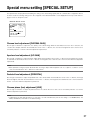
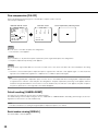
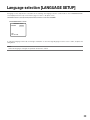
1
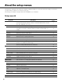
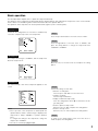
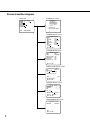
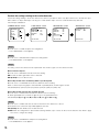
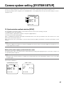
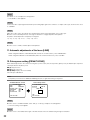
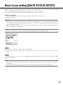
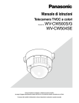
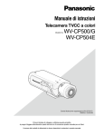
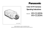
Operating Instructions
Color CCTV Camera
Model No.
WV-CW504F/WV-CW504FK
WV-CW504S/WV-CW504SK
This illustration represents WV-CW504F.
Before attempting to connect or operate this product,
please read these instructions carefully and save this manual for future use.
No model number suffix is shown in this manual.
Preface
About the user manuals
The operating instructions of the camera consist of 2 sets: these operating instructions (PDF) and Installation Guide.
This document explains how to configure the settings of the camera.
Refer to the installation guide for further information about how to install the camera.
Adobe® Reader® is required to read PDF. When the Adobe® Reader® is not installed on the PC, download the latest Adobe®
Reader® from the Adobe web site and install it.
Trademarks and registered trademarks
Adobe and Reader are either registered trademarks or trademarks of Adobe Systems Incorporated in the United States and/or other
countries.
2
Contents
Preface................................................................................ 2
About the user manuals.................................................. 2
Trademarks and registered trademarks.......................... 2
About the setup menus....................................................... 4
Setup menu list............................................................... 4
Basic operation............................................................... 5
Screen transition diagram............................................... 6
Camera title setting [CAMERA ID]....................................... 7
Camera operation setting [CAMERA SETUP]..................... 8
1. Register a scene file [SCENE1/SCENE2].................... 8
2. Light quantity control method selection [ALC]........... 9
SUPER-D5 (super dynamic function).......................... 9
SUPER-D5 setting...................................................... 9
3. Electronic shutter setting [SHUTTER]......................... 11
4. Gain control setting [AGC].......................................... 12
5. Electronic sensitivity enhancement setting
[SENS UP].................................................................. 12
6. White balance setting [WHITE BAL]........................... 12
Manual fine adjustment of white balance................... 13
7. Digital noise reduction function setting [DNR]............ 14
8. Black-and-white mode setting [BW MODE]............... 14
9. i-VMD setting [i-VMD]................................................. 15
Perform the settings relating to the motion
detection...................................................................... 16
Perform the settings relating to the detection of
appearance/disappearance of stationary objects...... 17
Set the detection areas............................................... 18
Setting of scene change detection ............................ 19
Configure frame display.............................................. 20
Configure alarm notification........................................ 20
Camera system setting [SYSTEM SETUP].......................... 21
10. Synchronization method selection [SYNC]............... 21
Setting of the power supply synchronization (LL)
mode......................................................................... 21
11. Automatic adjustments of the focus [LENS]............. 22
12. Privacy zone setting [PRIVACY ZONE]...................... 22
13. Image stabilizer setting [STABILIZER]..................... 23
14. Electronic zoom setting [EL-ZOOM]......................... 24
15. Display setting of vertical or horizonal flip
[UPSIDE-DOWN]....................................................... 24
Back focus setting [BACK-FOCUS SETUP]........................
Special menu setting [SPECIAL SETUP].............................
Chroma level adjustment [CHROMA GAIN]....................
Aperture level adjustment [AP GAIN]..............................
Pedestal level adjustment [PEDESTAL]..........................
Chroma phase (hue) adjustment [HUE]..........................
Flaw compensation [PIX OFF]........................................
Default resetting [CAMERA RESET]...............................
Serial number viewing [SER.NO.]...................................
Language selection [LANGUAGE SETUP]..........................
Shortcut operation..............................................................
25
27
27
27
27
27
28
28
28
29
30
3
About the setup menus
Performing each setting item in the setup menu should be completed in advance to use this unit. Perform the settings for each item in
accordance with the conditions of the camera shooting area.
The following is an example of setup procedure when LANGUAGE is set to ENGLISH.
Setup menu list
Setup item
CAMERA ID
CAMERA
Description
This item specifies the camera title. The camera title that indicates the camera location and other information about the camera is created with alphanumerics and symbols, and is displayed on the screen.
Reference
Pages
7
Performs the camera operation settings.
8
Selects a scene file. It is possible to register and save the settings as a scene file in
case that it is necessary to change the settings such when shooting at night or on
holidays.
8
ALC
Selects the method of controlling the quantity of light.
9
SHUTTER
Specifies the electronic shutter speed.
11
AGC
Specifies gain adjustment.
12
SENS UP
Specifies electronic sensitivity enhancement.
12
WHITE BAL
Specifies white balance adjustment.
12
DNR
Selects the level of the digital noise reduction function.
14
BW MODE
Performs each setting regarding the black-and-white mode such as switching
between color and black-and-white images.
Performs settings regarding intelligent VMD (Video Motion Detector) such as motion
detection and object abandonment/removal detection.
Performs the settings regarding the camera system such as synchronization and privacy zone.
SCENE1/SCENE2
i-VMD
SYSTEM
14
15
21
SYNC
Specifies the synchronization type.
21
LENS
Performs automatic adjustments of the focus.
22
PRIVACY ZONE
Hides undesired portions in the camera shooting area.
22
STABILIZER
Decides whether or not to enable the image stabilizer.
23
EL-ZOOM
Toggles the electronic zoom on and off.
24
UPSIDE-DOWN
Flips the camera images vertically or horizontally.
24
Selects the back focus setting type and performs fine adjustment.
25
CHROMA GAIN
Adjusts the chroma level.
27
AP GAIN
Adjusts the aperture level.
27
PEDESTAL
Adjusts the pedestal (brightness) level.
27
HUE
Adjusts the chroma phase (hue).
27
PIX OFF
Corrects image defects such as flaws.
28
CAMERA RESET
Restores the settings in the setup menu to the default settings.
28
SER.NO.
Displays the serial number of this unit.
28
Selects a language to be used in the setup menu.
29
BACK-FOCUS
SPECIAL
LANGUAGE
4
Basic operation
The description below explains how to operate the setup menu basically.
The operations in the setup menu are performed with the operation buttons after calling up the setup menu on the connected video
monitor. Refer to the installation guide for further information about the operation buttons.
The operations in the setup menu can also be performed through the system controller (option).
Screenshot 1
Hold down the setting button for more than 2 simultaneously
seconds to call up the top screen of the setup menu.
MODEL
WV-CW504
CAMERA ID
OFF
CAMERA
SYSTEM
BACK-FOCUS
SPECIAL
LANGUAGE
END
SETUP DISABLE
Step 1
Press the up or down button to move the cursor to "END".
Step 2
Press the right button to move the cursor to "SETUP", and
press the setting button to change the setup mode from
"DISABLE" to "ENABLE".
Screenshot 2
The setup mode changes to "ENABLE", and the setup menu
becomes ready to be set.
MODEL
WV-CW504
CAMERA ID
OFF
CAMERA
SYSTEM
BACK-FOCUS
SPECIAL
LANGUAGE
END
Step 3
Move the cursor to the item to be set, and press the setting
button.
SETUP ENABLE
Screenshot 3
The selected setup screen in the setup menu appears on the
screen.
**CAMERA SETUP**
SCENE1
ALC
ALC
SHUTTER
OFF
AGC
ON(HIGH)
SENS UP
OFF
WHITE BAL
ATW1
DNR
HIGH
BW MODE
AUTO1
i-VMD
RET TOP END
Note:
• If the top screen of the setup menu is called up with the
operation buttons while a camera image is displayed, the
setup mode is always "DISABLE" to prevent operation
errors.
To configure the settings in the setup menu, change the
setup mode to "ENABLE".
• The cursor is a reversely highlighted part.
Step 4
Perform the settings for each item.
• Selection of setting item:
Press the up or down button to move the cursor.
• Change of settings:
Press the right or left button.
• Display of advanced setup screen:
Press the setting button when "O" is attached to the target setting item.
• Return to previous setup screen:
Move the cursor to "RET" and press the setting button.
• Return to the top screen:
Move the cursor to "TOP" and press the setting button.
Step 5
To return to the camera image screen, move the cursor to
"END" and press the setting button.
5
Screen transition diagram
Top screen
"CAMERA ID" screen
MODEL
WV-CW504
CAMERA ID
OFF
CAMERA
SYSTEM
BACK-FOCUS
SPECIAL
LANGUAGE
END
**CAMERA ID**
0123456789
ABCDEFGHIJKLM
NOPQRSTUVWXYZ
().,'":;&#!?=
+-*/%$
SPACE POSI
RET TOP END RESET
................
SETUP ENABLE
"CAMERA SETUP" screen
**CAMERA SETUP**
SCENE1
ALC
ALC
SHUTTER
OFF
AGC
ON(HIGH)
SENS UP
OFF
WHITE BAL
ATW1
DNR
HIGH
BW MODE
AUTO1
i-VMD
RET TOP END
"SYSTEM SETUP" screen
**SYSTEM SETUP**
INT
PANASONIC
SYNC
LENS
PRIVACY ZONE
STABILIZER
EL-ZOOM
UPSIDE-DOWN
OFF
OFF
OFF
OFF
RET TOP END
"BACK-FOCUS SETUP" screen
**BACK-FOCUS SETUP**
ABF
PUSH SW
MANUAL-ADJ
C/L
B/W
AUTO
SETUP-SW LOCK OFF
NEAR
FAR
.........|.........
INDICATOR XXXX
RET TOP END
"SPECIAL SETUP" screen
**SPECIAL SETUP**
...|...128
CHROMA GAIN
...|... 32
AP GAIN
...|... 32
PEDESTAL
...|... 0
HUE
+
PIX OFF
CAMERA RESET
PUSH SW
SER.NO. XXXXXXXX
RET TOP END
"LANGUAGE SETUP" screen
**LANGUAGE SETUP**
LANGUAGE
SET
RET TOP END
6
ENGLISH
Camera title setting [CAMERA ID]
This item specifies the camera title. The camera title that indicates the camera location and other information about the camera is created with alphanumerics and symbols, and is displayed on the screen. The camera title is named with up to 16 characters.
Follow the procedure below to specify the camera title.
Top screen
MODEL
WV-CW504
CAMERA ID
ON
CAMERA
SYSTEM
BACK-FOCUS
SPECIAL
LANGUAGE
END
SETUP ENABLE
"CAMERA ID" screen
**CAMERA ID**
0123456789
ABCDEFGHIJKLM
NOPQRSTUVWXYZ
().,'":;&#!?=
+-*/%$
Display positioning screen
FLOOR 1
SPACE POSI
RET TOP END RESET
................
Editing area
Step 1
Select "ON" for "CAMERA ID", and then press the setting button.
→ The "CAMERA ID" screen appears.
Important:
• When "CAMERA ID" is set to "OFF", the camera title does not appear even after setting the camera title.
Step 2
Move the cursor to the target item with use of the up, down, right, and left buttons, and press the setting button to enter the character.
→ The entered characters are displayed in the editing area.
<Character entry>
• To revise a character, move the arrow (↑) in the entry range to a wrong character with use of the right or left button, and enter a
correct character.
• To enter a blank, move the cursor to "SPACE" and press the setting button.
• To delete all the entered characters, move the cursor to "RESET" and press the setting button.
Step 3
Move the cursor to "POSI" and press the setting button after title entry.
→ The display positioning screen appears.
Step 4
Use the up, down, right, and left buttons to decide the title position and press the setting button.
→ The camera title and title position are specified.
7
Camera operation setting [CAMERA SETUP]
The following describes the camera operation settings. The following settings can be configured on the "CAMERA SETUP" screen
displayed from the top screen. Refer to page 5 for how to call up the screen.
The settings configured on the "CAMERA SETUP" screen will be saved as a scene file.
"CAMERA SETUP" screen
q
w
e
r
t
y
u
i
o
**CAMERA SETUP**
SCENE1
ALC
ALC
SHUTTER
OFF
AGC
ON(HIGH)
SENS UP
OFF
WHITE BAL
ATW1
DNR
HIGH
BW MODE
AUTO1
i-VMD
RET TOP END
1. Register a scene file [SCENE1/SCENE2]
It is possible to register 2 patterns of scene file. For example, when different settings are to be applied between day and night,
SCENE1 can be applied in the daytime and SCENE2 at night.
Change between the scene files can be made on the shortcut operation. (+ page 30)
"SCENE1" is set as the default setting.
Screen when "SCENE1" is selected
**CAMERA SETUP**
SCENE1
ALC
ALC
SHUTTER
OFF
AGC
ON(HIGH)
SENS UP
OFF
WHITE BAL
ATW1
DNR
HIGH
BW MODE
AUTO1
i-VMD
RET TOP END
Screen when "SCENE2" is selected
**CAMERA SETUP**
SCENE2
ALC
ALC
SHUTTER
OFF
AGC
ON(HIGH)
SENS UP
OFF
WHITE BAL
ATW1
DNR
HIGH
BW MODE
AUTO1
i-VMD
COPY(SCENE1)
RET TOP END
Step 1
After confirming that "SCENE1" is selected, configure the settings of "ALC" through "i-VMD". (☞ pages 9 - 20)
When using while changing the scene files, go to step 2.
Step 2
Move the cursor to "SCENE1" and use the right or left button to select "SCENE2".
→ The "COPY(SCENE1)" screen will be displayed.
Step 3
To configure the settings of "SCENE2" using the settings of "SCENE1", press the setting button after moving the cursor to
"COPY(SCENE1)".
→ The settings of "SCENE1" will be copied to "SCENE2".
Step 4
Edit the settings to be changed and saved as the settings of "SCENE2".
The number displayed at the right side of the title on each setting screen
inidicates a scene file number.
**ALC CONT**(1)
BACK LIGHT COMP
SUPER-D5
ON
LEVEL
...|... 0
+
MANUAL ABS
RET TOP END
8
Scene file
number
Step 5
Move the cursor to "SCENE1" and press the right or left button to select "SCENE1" to resume normal operation.
2. Light quantity control method selection [ALC]
The method of controlling the quantity of light is selected from the following.
ALC (default): The iris of the lens is automatically adjusted in accordance with the brightness of a subject. Select "ALC" when using
the SUPER-D5 function or when using an ALC lens. Refer to the following when configuring the SUPER-D5 settings.
ALC+: Controls the quantity of light with a combination of the electronic shutter and auto iris. This selection is suitable at shooting a
bright subject such as an outdoor subject with auto iris lens. Be aware that flicker may occur when a subject is under fluorescent
lighting.
SUPER-D5 (super dynamic function)
If there is high contrast between the bright and dark areas in a shooting zone, the
dark area becomes less visible because the camera adjusts the iris in accordance
with the bright area. Conversely, adjusting the lens brightness for the darker areas
causes the brighter areas to become washed out.
The SUPER DYNAMIC function digitally combines an image that is set up for a clear
view of the brighter areas with an image that is set up for a clear view of the darker
areas, creating a final image that preserves overall detail.
Subject in the dark
area is hard to notice.
Creates a clearer
image by digitally
combining images
SUPER-D5 setting
When "ALC" is selected, the SUPER-D5 function is available.
Follow the procedure below.
"CAMERA SETUP" screen
**CAMERA SETUP**
SCENE1
ALC
ALC
SHUTTER
OFF
AGC
ON(HIGH)
SENS UP
OFF
WHITE BAL
ATW1
DNR
HIGH
BW MODE
AUTO1
i-VMD
RET TOP END
"ALC CONT" screen
**ALC CONT**(1)
BACK LIGHT COMP
SUPER-D5
ON
LEVEL
...|... 0
+
MANUAL ABS
RET TOP END
Subject in the bright
area is hard to notice.
Area setting screen
**AREA
POSITION
**(1)
PUSH SW
UPPER LEFT
DEL
RET TOP END
Step 1
Select "ALC" and press the setting button.
→ The "ALC CONT" screen appears.
Note:
• When "ALC" is set to "ALC+" and the setting button is pressed, the "ALC+CONT" screen appears.
• When "ALC+" is selected, the SUPER-D5 function is disabled. "---" appears and "OFF" is selected.
Step 2
Move the cursor to "SUPER-D5" and select the item from the following:
ON (default): Activates the SUPER-D5 function all the time. (☞ page 10)
ON (i-VMD): Activates the SUPER-D5 function all the time. (☞ page 10)
In addition to the SUPER-D5 function, the motion detection function also works.
OFF: Deactivates the SUPER-D5 function. (☞ page 10)
9
Note:
• When "ON" or "ON(i-VMD)" is selected for "SUPER-D5", the following settings will be restricted.
SHUTTER: Only OFF and 1/100 are available. (☞ page 11)
SENS UP: Only "OFF" and "AUTO" become available. (☞ page 12)
• When "ON" or "ON(i-VMD)" is selected for "SUPER-D5", a shadow (black line) may appear at the boundary between a brighter
area and a darker area. This is not a malfunction.
• When "ON" or "ON(i-VMD)" is selected for "SUPER-D5", the SUPER-D5 function will become more effective by slightly incrementing "LEVEL". However, flickering or noise may be observed frequently when "LEVEL" is too much incremented.
• When flickering or noise is observed frequently due to the illumination of light, select "OFF".
(1) When flickering or color deterioration is observed
(2) When noise is produced in a bright area on the screen
• When "ON(i-VMD)" is selected for "SUPER-D5", performance of the motion detection will vary depending on the i-VMD settings.
(☞ Steps 4 - 6 on page 18)
When using the SUPER-D5 function
Follow the procedure below.
Step 1
Move the cursor to "LEVEL" and use the right or left button to adjust the level.
Step 2
The dark area of the object is automatically corrected to lighten it.
Move the cursor to "MANUAL ABS" and press the setting button.
→ The area setting screen appears.
Step 3
Move the cursor to "POSITION" and press the setting button.
Step 4
Use the up, down, right, and left buttons to determine the left upper position of the area to be set and press the setting button.
Step 5
Use the up, down, right, and left buttons to determine the right lower position of the area and press the setting button.
Note:
• To delete an area, move the cursor to "DEL" and press the setting button.
• The area to be brighter becomes circular.
• The bright level of an area cannot be specified.
• Only one area can be set.
When not using the SUPER-D5 function
Follow the procedure below.
Step 1
When the SUPER-D5 function is set to "OFF", bright areas of an image are masked to facilitate the visibility of dark areas.
Move the cursor to "MASK SET" and press the setting button.
→ The mask setting screen appears.
10
"ALC CONT" screen
Mask setting screen
**ALC CONT**(1)
BACK LIGHT COMP
SUPER-D5
OFF
MASK SET
LEVEL
MANUAL ABS
Area setting screen
**AREA
POSITION
**(1)
PUSH SW
UPPER LEFT
...|... 0
+
RET TOP END
DEL
RET TOP END
Step 2
Mask bright areas.
Use the up, down, right, and left buttons to select an area to be masked and press the setting button. When the selected area is
masked, the masked area will start blinking (between stripes and white screen). When selecting another area after masking, the
masked area will be edisplayed in white. Repeat the above procedure to mask other areas as necessary.
Note:
• To cancel the masking, select the masked area to be canceled, and then press the setting button.
• To cancel all the masking, hold down the right and left buttons for more than 2 seconds simultaneously.
Step 3
Hold down the setting button for more than 2 seconds simultaneously after completion of masking.
→ The "ALC CONT" or "ALC+ CONT" screen appears again.
Step 4
Move the cursor to "LEVEL" and use the right or left button to adjust the level.
Step 5
The dark area of the object is automatically corrected to lighten it.
Move the cursor to "MANUAL ABS" and press the setting button.
→ The area setting screen appears.
Step 6
Move the cursor to "POSITION" and press the setting button to select an area.
The setup procedure is the same as the setting operation in the process of SUPER-D5 function. (+ Steps 4 - 5 on page 10)
3. Electronic shutter setting [SHUTTER]
The variation in electronic shutter speed allows users to perform the following.
• Increased shutter speed prevents blurring fast-moving subjects.
• If flicker is observed under fluorescent lighting of 50 Hz, selection of "1/100" for the speed can reduce flicker.
The electronic shutter speed is selectable from the following: The setting of the SUPER-D5 function restricts the available setting
range.
When the SUPER-D5 function is set to "OFF": OFF (1/60) (default), 1/100, 1/250, 1/500, 1/1 000, 1/2 000, 1/4 000, and
1/10 000
When the SUPER-D5 function is set to "ON" or "ON(i-VMD)": OFF (1/60) (default), 1/100
Note:
• When "ALC" is set to "ALC+" (+ page 9), "---" appears and the electronic shutter function cannot be activated.
• If the controller, WV-CU254 or WV-CU204 is used, SW LED and the status of "SHUTTER" are not correctly displayed.
11
4. Gain control setting [AGC]
Select a gain control setting from the following.
ON (HIGH) (default)/ON (MID)/ON (LOW): Automatically increases the gain to make the screen brighter when the illuminance of the
subject becomes darker.
HIGH, MID and LOW indicate the gain level.
OFF: Does not increase the gain.
Note:
• When "SENS UP" is set to the AUTO mode, “AGC” cannot be set to “OFF”. 5. Electronic sensitivity enhancement setting [SENS UP]
Use of the electronic sensitivity enhancement function increases the quantity of light stored on the CCD, and accordingly the image
becomes brighter. The magnification is unchanged for selection of FIX, and the magnification is changeable in accordance with the
illuminance of a photographic subject for selection of AUTO.
The magnification of the electronic sensitivity is selectable from the following. The setting of the SUPER-D5 function restricts the available setting range.
When the SUPER-D5 function is set to "OFF": OFF (default)/X2 AUTO/X4 AUTO/X6 AUTO/X10 AUTO/X16 AUTO/X32 AUTO/
OFF/X2 FIX/X4 FIX/X6 FIX/X10 FIX/X16 FIX/X32 FIX
When the SUPER-D5 function is set to "ON" or "ON (i-VMD)": OFF (default)/X2 AUTO/X4 AUTO/X6 AUTO/X10 AUTO/X16
AUTO/X32 AUTO
Note:
• When "ALC" is set to "ALC+" (+ page 9), or "SHUTTER" is set to "1/100" (+ page 11), only the AUTO mode is enabled.
• When "SHUTTER" is set to "OFF" or other than "1/100", the electronic sensitivity enhancement setting cannot be performed. "---"
appears and "OFF" is selected.
• It is impossible to select "AUTO" for "SENS UP" and "1/100" for "SHUTTER" using the following system controller. Use the operation buttons for the setting.
WV-CU300, WV-CU354, WV-CU204, WV-CU254
• When the magnification of "SENS UP" is increased, the screen becomes coarser, more whitish, or more flawed. However, this
phenomenon is normal.
• If the controller, WV-CU254 or WV-CU204 is used, SW LED and the status of "SENS UP" are not correctly displayed.
6. White balance setting [WHITE BAL]
The white balance adjustment is selectable from the following.
ATW1 (default): Activates the automatic color temperature tracking mode. The camera continuously measures the color temperature
of the light source and automatically adjusts the white balance. The adjustment of the color temperature ranges from approx. 2
700 K to 6 000 K.
Note:
If the situation meets one of the following or other, color may not be accurately reproduced.
• The subject is mostly highly-colored.
• The photographic atmosphere is under the bright blue sky or at nightfall.
• The illumination of the light illuminating the subject is insufficient.
ATW2: Activates the sodium lamp automatic color temperature tracking mode. The camera automatically achieves an optimal white
balance under the sodium lamp. The adjustment of the color temperature ranges from approx. 2 000 K to 6 000 K.
AWC: Activates the automatic white balance control mode. This adjustment is suitable for a location where a light source is stable.
The adjustment of the color temperature ranges from approx. 2 000 K to 10 000 K. When "AWC" is selected, the white balance
needs to be adjusted.
12
When "AWC" is selected, follow the steps below to adjust the white balance.
"CAMERA SETUP" screen
**CAMERA SETUP**
SCENE1
ALC
ALC
SHUTTER
OFF
AGC
ON(HIGH)
SENS UP
OFF
WHITE BAL
AWC PUSH SW
DNR
HIGH
BW MODE
AUTO1
i-VMD
RET TOP END
Step 1
Set "WHITE BAL" to "AWC" and press the left button to change to "AWC → PUSH SW".
Step 2
Press the setting button and adjust the white balance.
"PUSH SW" is reversely highlighted during adjustment. When the reversely highlighted display is restored, the white balance adjustment is completed.
Step 3
Press the right button to select "AWC".
Refer to the following for fine adjustment of the white balance.
Note:
• The adjustment of the color temperature ranges from approx. 2 000 K to 10 000 K. If the correct range is out of this adjustment
range or lighting directed to a subject is too dark, the white balance may not completely adjusted. In such a case, "PUSH SW"
stays reversely highlighted.
Manual fine adjustment of white balance
The white balance is manually fine adjusted after white balance automatically adjustment in the automatic color temperature tracking
mode (ATW1, ATW2) or automatic white balance control mode (AWC).
Follow the procedure below.
"CAMERA SETUP" screen
**CAMERA SETUP**
SCENE1
ALC
ALC
SHUTTER
OFF
AGC
ON(HIGH)
SENS UP
OFF
WHITE BAL
ATW1
DNR
HIGH
BW MODE
AUTO1
i-VMD
RET TOP END
Fine adjustment screen
**ATW1**(1)
R
...|... 0
+
B
...|... 0
+
RET TOP END
Step 1
Set "WHITE BAL" to "ATW1", "ATW2" or "AWC" and press the setting button.
→ The fine adjustment screen appears.
Step 2
Move the cursor to "R" and "B" and use the right or left button to fine adjust the level for each.
When the level indicator moves in the "+" direction, the color becomes deeper, and when the level indicator moves in the "–" direction, the color becomes lighter.
13
7. Digital noise reduction function setting [DNR]
The digital noise reduction function reduces noise automatically under the condition of low illuminance.
The effect level of the noise reduction function is selectable from the following:
LOW: Low level of noise reduction (small residual image)
HIGH (default): High level of noise reduction (large residual image)
8. Black-and-white mode setting [BW MODE]
The settings relating to the black-and-white mode can be configured. Follow the procedure below.
"CAMERA SETUP" screen
**CAMERA SETUP**
SCENE1
ALC
ALC
SHUTTER
OFF
AGC
ON(HIGH)
SENS UP
OFF
WHITE BAL
ATW1
DNR
HIGH
BW MODE
AUTO1
i-VMD
RET TOP END
"BW MODE" screen
**BW MODE**(1)
AUTO1
LEVEL
HIGH
DURATION TIME .|..
S L
BURST(BW)
ON
RET TOP END
Step 1
Move the cursor to "BW MODE" and select the black-and-white control from the following:
AUTO1 (default): Automatically toggles between color and black-and-white images in accordance with the screen brightness (illuminance). The black-and-white mode is selected for dark images, and the color mode is selected for bright images.
AUTO2: Uses a near-infrared light source at nighttime.
ON: Displays black-and-white images.
OFF: Displays color images.
Note:
• The auto back focus function also allows users to correct out of focus when changing between color and black-and-white images. (+ page 25)
• If a subject is always moving or the screen is occupied with a uniform color, brightness determination may be not performed successfully because the brightness is merely determined by information from the CCD image sensor. When "AUTO2" is selected,
the wave length of the light source shall be 800 nm or longer.
Step 2
Press the setting button.
→ The "BW MODE" screen appears.
Step 3
Move the cursor to "LEVEL" and select a brightness level at which switching between color and black-and-white images is performed
from the following:
LOW: Switches from color to black-and-white images when the ambient brightness (illuminance) of the camera is approx. 0.1 lx or
less.
HIGH (default): Switches from color to black-and-white images when the ambient brightness (illuminance) of the camera is approx.
0.2 lx or less.
Note:
14
• To obtain color images, a sufficient level of illuminance (approx. 30 lx or more) is required.
• The switching illuminance level varies with subjects, light sources, and lenses.
• The switching illuminance level varies in accordance with AGC setting. (+ page 12)
• The switching illuminances described above are reference values. The switching illuminance shall be decided based on the actual
installation environment.
Step 4
Move the cursor to "DURATION TIME" and select a time for switching between color and black-and-white images from the following:
(default: 10 seconds)
2 sec. - 10 sec. - 30 sec. - 60 sec.
(S)
(L)
Step 5
Move the cursor to "BURST (BW)", and decide whether or not to provide a burst signal output in the black-and-white mode.
ON (default): Provides a burst signal output.
OFF: Does not provide any burst signal output.
Note:
• Images may not be displayed appropriately without burst signals when camera images are displayed in the black-and-white mode
depending on a monitor or VCR model to be used. In such a case, set the burst signal output to "ON".
9. i-VMD setting [i-VMD]
The intelligent motion detection function allows the camera to detect motion and appearance/disappearance of an object or interference with the camera. Detection of motion and appearance/disappearance of an object or interference with the camera can be
announced by issuing an alarm signal or displaying a frame on the screen.
Important:
• The following circumstances may result in detection failure or false detection: Adjusting the detection area and sensitivity may
cause detection failure.
• Not enough difference in brightness between the background and the moving photographic subject, or significant changes in
brightness
• Dirt or water drops on the lens
• Insufficient brightness, for example, when shooting at night
• The subject is moving straight at the camera
• The subject is moving too fast or too slow
• The subject is too small or too large
• There are too many moving objects
• Light reflected through a window or from a road surface
• The camera is shaking
• Entry of outside light, such as sunlight or the headlights of a car
• Flickering fluorescent light
• Scene change detection may fail in the following cases:
• The lens is partially covered or covered with a transparent item
• The photographic subjects before and after changing the camera direction are similar
• False detection may occur for approx. 1 minute after turning on the power, after completing settings in the SETUP menu, or after
changing the camera view angle.
15
Perform the settings relating to the motion detection
Perform the settings relating to the motion detection as follows. It is possible to detect only objects that moves to the direction specified in advance or objects that keeps on moving for a certain duration. Up to 4 motions can be simultaneously detected.
Follow the procedure below.
"CAMERA SETUP" screen
**CAMERA SETUP**
SCENE1
ALC
ALC
SHUTTER
OFF
AGC
ON(HIGH)
SENS UP
OFF
WHITE BAL
ATW1
DNR
HIGH
BW MODE
AUTO1
i-VMD
RET TOP END
"i-VMD SETUP" screen
"MOTION DET" screen
"SENSITIVITY" screen
**i-VMD SETUP**(1)
MOTION DET
OBJECT DET
OFF
SCENE CHANGE
OFF
**MOTION DET**(1)
MOTION
OFF
LOITERING
OFF
DIRECTION
OFF
**SENSITIVITY**(1)
SENSITIVITY LOW
MIN SIZE
OFF
INDICATOR
ALARM
AREA
SENSITIVITY
OFF
CONT
RET TOP END
ALL
RET TOP END
RET TOP END
Step 1
Move the cursor to "i-VMD" and press the setting button.
→ The "i-VMD SETUP" screen appears.
Step 2
Move the cursor to "MOTION DET" and press the setting button.
→ The "MOTION DET" screen appears.
Step 3
The setting of the motion detection mode is performed. This unit has 3 types of motion deteciton modes.
Detect motion of objects
Move the cursor to "MOTION" and select from the following.
ON: Provides an alarm signal when motion is detected.
OFF (default): Does not detect motion.
Detect objects that move continuously within a specified period
Move the cursor to "LOITERING" and select the duration from the following:
When a continuously moving object is detected within a specified period, an alarm signal is issued.
OFF (default)/ON (5 s)/ON (10 s)/ON (20 s)/ON (30 s)/ON (40 s)/ON (50 s)/ON (1 min)
a
Detect objects that move into the specified direction
Move the cursor to "DIRECTION" and select the direction from the following:
An alarm signal will be sent out when an object moves to the specified direction.
OFF (default)/ON (c)/ON (c )/ON (a)/ON ( )/ON (d)/ON (d )/ON ([ )/ON ([ )
Step 4
Move the cursor to "AREA" and select an area for which the motion detection is to be set.
All the alarm actions selected in step 3 will be applied to this area.
ALL (default): All areas will be set as the detection area.
SETUP: When the setting button is pressed after selecting "SETUP", up to 2 areas can be set as the detection area. Refer to page
18 for how to configure the settings.
Step 5
Move the cursor to "SENSITIVITY" and press the setting button.
→ The "SENSITIVITY" screen appears.
16
Step 6
Set the detection sensitivity and the minimum size of objects detected. Perform the setup while viewing the detection result displayed
on the screen.
Set the detection sensitivity
Move the cursor to "SENSITIVITY" and select one of the following options for the detection sensitivity:
LOW (default)/MID/HIGH
Set the minimum size of objects detected
Move the cursor to "MIN SIZE" and select the minimum size of objects detected from the following: The size options will be displayed
in a green frame in the center of the screen. In "OFF" position, any object will be detected regardless of its size.
Perform the setup while viewing the detection result displayed on the screen.
OFF (default)/SMALL/MEDIUM/LARGE
Note:
• The detection sensitivity and minimum size selected in this step will be applied to all the alarm actions selected in step 3.
• The detection areas set in step 4 will be displayed as a white frame on the "SENSITIVITY" screen.
• When a motion is detected, a blue frame appears and changes to a red frame after a given time (approx. 1 second.) on the
"SENSITIVITY" screen. In operation, an alarm signal is provided when the frame changes to red.
Perform the settings relating to the detection of appearance/disappearance of stationary objects
Perform the settings relating to the detection of appearance/disappearance of stationary objects as follows. Up to 4 appearances/
disappearances of stationary objects can be simultaneously detected. However, use of the scene change detection function
decreases the maximum simultaneous detectable appearances/disappearances of stationary objects to 3.
Follow the procedure below.
"CAMERA SETUP" screen
**CAMERA SETUP**
SCENE1
ALC
ALC
SHUTTER
OFF
AGC
ON(HIGH)
SENS UP
OFF
WHITE BAL
ATW1
DNR
HIGH
BW MODE
AUTO1
i-VMD
RET TOP END
"i-VMD SETUP" screen
**i-VMD SETUP**(1)
MOTION DET
OBJECT DET
ON
SCENE CHANGE
OFF
INDICATOR
ALARM
OFF
CONT
RET TOP END
"OBJECT" screen
**OBJECT DET**(1)
REMOVAL AND LEFT BEHIND
DURATION TIME
AREA
SENSITIVITY
RET TOP END
"SENSITIVITY" screen
**SENSITIVITY**(1)
MIN SIZE
OFF
10s
ALL
RET TOP END
Step 1
Move the cursor to "i-VMD" and press the setting button.
→ The "i-VMD SETUP" screen appears.
Step 2
Move the cursor to "OBJECT DET" and press the setting button.
→ The "OBJECT DET" screen appears.
Step 3
Move the cursor to "DURATION TIME" and select the wait time of appearance/disappearance of stationary objects from the following.
10 s (default)/20 s/30 s/40 s
17
Step 4
Move the cursor to "AREA" and select the area for which the detection of appearance/disappearance of stationary objects is to be
set.
ALL (default): All areas will be set as the detection area.
SETUP: When the setting button is pressed after selecting "SETUP", up to 2 areas can be set as the detection area. Refer to the
description below for how to configure the settings.
Step 5
Move the cursor to "SENSITIVITY" and press the setting button.
→ The "SENSITIVITY" screen appears.
Step 6
Move the cursor to "MIN SIZE" and select the minimum size of objects detected from the following: The size options will be displayed
in a green frame in the center of the screen. In "OFF" position, any object will be detected regardless of its size.
Perform the setup while viewing the detection result displayed on the screen.
OFF (default)/SMALL/MEDIUM/LARGE
Note:
• The detection areas set in step 4 will be displayed as a white frame on the "SENSITIVITY" screen.
• When appearance/disappearance of a stationary object is detected, a red frame will be displayed on the "SENSITIVITY" screen.
Set the detection areas
Set the detection areas for motion detection and the detection of appearance/disappearance of stationary objects.
Up to 2 detection areas can be set.
Follow the procedure below.
"MOTION DET" screen
**MOTION DET**(1)
MOTION
OFF
LOITERING
OFF
DIRECTION
OFF
AREA
SENSITIVITY
RET TOP END
SETUP
"OBJECT DET" screen
Area setting screen
**OBJECT DET**(1)
REMOVAL AND LEFT BEHIND
**AREA 1 /2**(1)
DURATION TIME
AREA
SENSITIVITY
10s
SETUP
POSITION
RET TOP END
DEL
RET TOP END
Step 1
Move the cursor to "AREA" and select "SETUP", and then press the setting button.
→ The "AREA" screen appears.
Step 2
Move the cursor onto the number to select the area number using the right or left button.
Step 3
Move the cursor to "POSITION" and press the setting button.
18
PUSH SW
UPPER LEFT
Step 4
Use the up, down, right, and left buttons to determine the left upper position of the area to be set and press the setting button.
Note:
• The area corresponding to the selected number will be displayed in a green frame, while the other set areas are shown in a white
frame.
Step 5
Use the up, down, right, and left buttons to determine the right lower position of the area to be set and press the setting button.
→ The asterisk mark "*" will be displayed after the number and the area setting will be saved.
Note:
• To delete the area, select the area number and press the setting button after moving the cursor to "DEL".
• To change the settings of the area, select the area number and repeat from step 3.
Setting of scene change detection
This function detects a change in the subject state that occurs by covering the camera with a cloth, a cap, or others, or by changing
the camera direction largely.
Follow the procedure below.
"CAMERA SETUP" screen
**CAMERA SETUP**
SCENE1
ALC
ALC
SHUTTER
OFF
AGC
ON(HIGH)
SENS UP
OFF
WHITE BAL
ATW1
DNR
HIGH
BW MODE
AUTO1
i-VMD
RET TOP END
"i-VMD SETUP" screen
**i-VMD SETUP**(1)
MOTION DET
OBJECT DET
OFF
SCENE CHANGE
OFF
INDICATOR
ALARM
OFF
CONT
RET TOP END
Step 1
Move the cursor to "i-VMD" and press the setting button.
→ The "i-VMD SETUP" screen appears.
Step 2
Move the cursor to "SCENE CHANGE" and select from the following.
ON: Provides an alarm signal when scene change is detected.
OFF (default): Disables scene change detection.
19
Configure frame display
Follow the procedure below.
"CAMERA SETUP" screen
**CAMERA SETUP**
SCENE1
ALC
ALC
SHUTTER
OFF
AGC
ON(HIGH)
SENS UP
OFF
WHITE BAL
ATW1
DNR
HIGH
BW MODE
AUTO1
i-VMD
RET TOP END
"i-VMD SETUP" screen
**i-VMD SETUP**(1)
MOTION DET
OBJECT DET
OFF
SCENE CHANGE
OFF
INDICATOR
ALARM
OFF
CONT
RET TOP END
Step 1
Move the cursor to "i-VMD" and press the setting button.
→ The "i-VMD SETUP" screen appears.
Step 2
Move the cursor to "INDICATOR" and determine whether or not to display a frame around the screen from the following.
OFF (default): Does not display a frame.
ON(ALL): Displays a frame.
ON(OBJ): Display the appearance/disappearance frame only.
Configure alarm notification
Follow the procedure below.
"CAMERA SETUP" screen
**CAMERA SETUP**
SCENE1
ALC
ALC
SHUTTER
OFF
AGC
ON(HIGH)
SENS UP
OFF
WHITE BAL
ATW1
DNR
HIGH
BW MODE
AUTO1
i-VMD
RET TOP END
"i-VMD SETUP" screen
**i-VMD SETUP**(1)
MOTION DET
OBJECT DET
OFF
SCENE CHANGE
OFF
INDICATOR
ALARM
OFF
CONT
RET TOP END
Step 1
Move the cursor to "i-VMD" and press the setting button.
→ The "i-VMD SETUP" screen appears.
Step 2
Move the cursor to "ALARM" and configure alarm notification.
CONT (default): Continues to send alarm signals upon detection.
1TIME: Sends an alarm signal only once (100 ms) at detection start.
20
Camera system setting [SYSTEM SETUP]
Performs the settings relating to the camera system such as synchronization, alarm input/output terminal, and privacy zone.
The following settings can be configured on the "SYSTEM SETUP" screen displayed from the top screen. Refer to page 5 for how to
call up the screen.
"SYSTEM SETUP" screen
!0
!2
!4
**SYSTEM SETUP**
INT
PANASONIC
!1
SYNC
LENS
!3
PRIVACY ZONE
STABILIZER
EL-ZOOM
UPSIDE-DOWN
!5
OFF
OFF
OFF
OFF
RET TOP END
10. Synchronization method selection [SYNC]
This unit supports the following 3 types of synchronization methods, and one of the following is selected.
(1) Multiplexed vertical drive signal (VD2)
(2) Synchronization is performed on the basis of the power supply frequency.
(3) Internal synchronization (INT) (default)
Input of a multiplexed vertical drive signal (VD2) automatically switches to the VD2 synchronization even if the camera is set to other
than the VD2 synchronization method.
When other than the VD2 synchronization is selected, either the power supply synchronization or internal synchronization can be
selected.
Note:
• The power supply synchronization (LL) setting is changeable only in the 60 Hz areas. The power supply synchronization (LL) cannot be setup in the 50 Hz areas.
Setting of the power supply synchronization (LL) mode
The adjusting video signal of the camera and the criterial external synchronizing input signal (power) are connected to a 2-input oscilloscope and the phase is adjusted.
Note:
• Movement of the camera or presence of a spike noise in the power line may cause vertical phase change. In such a case, adjust
the phase again.
Follow the procedure below.
"SYSTEM SETUP" screen
**SYSTEM SETUP**
LL
PANASONIC
SYNC
LENS
PRIVACY ZONE
STABILIZER
EL-ZOOM
UPSIDE-DOWN
RET TOP END
OFF
OFF
OFF
OFF
"SYNC" screen
**SYNC**
V PHASE
COARSE
FINE
1(1--16)
...|...128
+
RET TOP END
21
Step 1
Set "SYNC" to "LL" and press the setting button.
→ The "SYNC" screen appears.
Step 2
Connect the video output signal and external synchronizing input signal of the camera to a 2-input oscilloscope, and move the cursor
to "COARSE".
Step 3
Adjust the oscilloscope to the vertical rate, and extend the vertical synchronizing part of the oscilloscope.
Move the cursor horizontally with use of the right or left button to roughly adjust the vertical phase.
The phase can be adjusted in 16 steps by 22.5 degrees.
1 (1--16) : 0 °/2 (1--16) : 22.5 °/· · ·/16 (1--16) : 337.5
Step 4
Move the cursor to "FINE", and fine adjust vertical phases.
11. Automatic adjustments of the focus [LENS]
• When using WV-CW504F or WV-CW504S (with a Panasonic x2 varifocal lens), select "PANASONIC".
• When using WV-CW504FK or WV-CW504SK (with a lens other than Panasonic), select "OTHER".
12. Privacy zone setting [PRIVACY ZONE]
When undesired portions in the camera shooting area (on the screen) exist, those portions (privacy zone) are hidden. Up to 8 portions
can be specified for the privacy zone.
ON (1): Grays the zone.
ON (2): Mosaics the zone.
OFF (default): Displays the zone normally.
Follow the procedure below.
Note:
• The privacy zone function is disabled at initializing the unit, i.e. right after turning on the power.
"SYSTEM SETUP" screen
**SYSTEM SETUP**
INT
PANASONIC
SYNC
LENS
PRIVACY ZONE
STABILIZER
EL-ZOOM
UPSIDE-DOWN
RET TOP END
ON(1)
OFF
OFF
OFF
Zone setting screen
**ZONE NUMBER 1 /8**
POSITION
PUSH SW
UPPER LEFT
DEL
RET TOP END
Step 1
Move the cursor to "PRIVACY ZONE", select "ON (1)" or "ON (2)", and press the setting button.
→ The zone setting screen appears.
Step 2
Move the cursor to the number at the right of the title and select the zone number using the right or left button.
22
Step 3
Move the cursor to "POSITION" and press the setting button.
Step 4
Use the up, down, right, and left buttons to determine the left upper position of the zone to be set and press the setting button.
Step 5
Use the up, down, right, and left buttons to determine the lower right position of the zone to be set and press the setting button.
→ The asterisk mark "*" will be displayed after the number and the zone setting will be saved.
Note:
• To delete a zone, select the zone number and press the setting button after moving the cursor to "DEL".
• To change the settings of a zone, select the zone number and repeat from step 3.
13. Image stabilizer setting [STABILIZER]
Whether or not to enable the image stabilizer is determined.
This function is effective for the case that the camera is installed on a power pole or other poles.
ON: Enables the image stabilizer.
OFF (default): Disables the image stabilizer.
Important:
• When "ON" is selected for the image stabilizer, the view angle becomes narrower and the resolution becomes lower. When "ON"
is selected for the image stabilizer, check the view angle and resolution at camera installation.
• The image stabilizer function may not work for the following subjects or conditions:
• Dark subject
• Less contrasty subject (e.g. white wall)
• Short cycled image shaking such as mechanical vibration
• Large amplitude image shaking
23
14. Electronic zoom setting [EL-ZOOM]
Select "On" or "Off" to determine whether or not to use the electronic zoom.
When "ON" is selected, the zoom factor and the panning/tilting settings can be configured.
ON: Uses the electronic zoom.
OFF (default): Does not use the electronic zoom.
Follow the procedure below.
"SYSTEM SETUP" screen
EL-zoom setting screen
**SYSTEM SETUP**
SYNC
INT
LENS
PANASONIC
**EL-ZOOM**
PRIVACY ZONE
STABILIZER
EL-ZOOM
UPSIDE-DOWN
RET TOP END
OFF
OFF
ON
OFF
ZOOM
PAN/TILT
PUSH SW
PUSH SW
Zoom setting screen
Pan/tilt setting screen
**EL-ZOOM**
ZOOM
PAN/TILT
PUSH SW
PUSH SW
**EL-ZOOM**
ZOOM
PAN/TILT
U ZOOM D
RET TOP END
RET TOP END
PUSH SW
PUSH SW
U TILT D/L PAN R
RET TOP END
Step 1
Move the cursor to "EL-ZOOM", select "ON" and press the setting button.
→ The "EL-ZOOM" screen will be displayed.
Step 2
Move the cursor to "PUSH SW" of "ZOOM" and press the setting button.
→ The zoom setting screen appears.
Step 3
Adjust the angular field of view by changing the electronic zoom factor (up to 2x) using the up or down button.
Note:
• When the zoom factor is incremented, resolution will be deteriorated.
Step 4
Move the cursor to "PUSH SW" of "PAN/TILT" and press the setting button.
→ The pan/tilt setting screen appears.
Step 5
Use the up, down, right, and left buttons to determine the image position and press the setting button.
The position can be changed in the range of zoom factor set in the "EL-ZOOM" screen.
Note:
• To reset to the default, hold down the right and left buttons for more than 2 seconds simultaneously while the zoom setting screen
or pan/tilt setting screen is displayed.
15. Display setting of vertical or horizonal flip [UPSIDE-DOWN]
Select "On" or "Off" to determine whether or not to display the camera images flipped vertically or horizontally. Image horizontal flip is
selected in accordance with the camera location (usage environment).
ON: Flips the camera images vertically or horizontally.
OFF (default): Does not flip camera images vertically or horizontally.
24
Back focus setting [BACK-FOCUS SETUP]
Selects the back focus setting type and performs fine adjustment. The following setting can be configured on the "BACK-FOCUS
SETUP" screen displayed from the top screen. Refer to page 5 for how to call up the screen.
The lens adjustment (☞ Installation Guide) shall be performed before the back focus adjustment.
<Back focus adjustment>
The back focus adjustment is performed by changing the distance between the lens and focal point.
Follow the procedure below.
Important:
• The auto back focus function is used for back focus adjustment at installation and for focus correction at switching between the
color and black-and-white modes after installation. This function is not a function that is supposed to be operated continuously
such as the auto focus function.
• When focus missing occurs due to secular change in the lens and installation environment or peripheral temperature change, the
back focus adjustment is required again.
Note:
• The back focus adjustment can be also performed through the operation buttons. (☞ Installation Guide.)
"BACK-FOCUS SETUP" screen
**BACK-FOCUS SETUP**
ABF
PUSH SW
MANUAL-ADJ
C/L
B/W
AUTO
SETUP-SW LOCK OFF
NEAR
FAR
.........|.........
INDICATOR XXXX FOCUSING
RET TOP END
Step 1
Move the cursor to "PUSH SW" of "ABF" and press the setting button.
→ The auto back focus function provides back focus adjustment to automatically focus on a subject located in the center of the
screen.
Step 2
To fine adjust the back focus, move the cursor to "MANUAL-ADJ", press the setting button, and use the right or left button to adjust
the back focus manually.
Note:
• Holding down the right and left buttons for more than 2 seconds simultaneously resets the back focus position to the CS mount
default position.
• The value of "INDICATOR" is a guide to adjust the back focus. The larger the value is, the sharper the image becomes.
25
Step 3
Move the cursor to "C/L ← → B/W" and select the back focus adjustment type from the following:
AUTO (default): Adjusts the back focus function automatically and corrects out of focus when switching between color and blackand-white images.
PRESET: Performs the preset movement to each specified back focus position when switching between color and black-and-white
images. The preset position is the back focus position specified last time, which was automatically memorized for each of color
images and black-and-white images.
FIX: Fixes the position after adjusting the back focus either automatically (ABF) or manually.
Step 4
Moving the cursor to "SETUP-SW LOCK" and selecting "ON" allow users to disable the back focus adjustment with the operation
buttons (default: OFF).
Important:
• The following are recommendation for back focus setting in accordance with subjects.
For such case (subject conditions) Select this (recommendation)
Back focus adjustment
"C/L ← → B/W" switching
• Normal subject
"ABF"
"AUTO"
• Frequently moving subj.
Fine adjustment with "MANUAL-ADJ"
"PRESET" or "FIX"
• Subj. with remarkable illuminance
after "ABF" or "MANUAL-ADJ"
change
• Subj. with low illuminance
• Too bright or reflective subj.
• Subj. through a window
• Place where the lens easily becomes
dirty
• Subj. with less contrast such as white
wall
• Subj. with remarkable depth
• Subj. with heavy flicker
• Subj. with horizontally parallel lines
such as a shutter
• We shall not responsible for any inconvenience, loss, or damage caused by the settings or results of the back focus function.
26
Special menu setting [SPECIAL SETUP]
The special menu setup is performed including the setting of the camera image quality and the communication configuration when a
receiver is used. The following settings are to be configured on the "SPECIAL SETUP" screen displayed from the top screen. Refer to
page 5 for how to call up the screen.
"SPECIAL SETUP" screen
**SPECIAL SETUP**
...|...128
CHROMA GAIN
...|... 32
AP GAIN
...
|... 32
PEDESTAL
...|... 0
HUE
+
PIX OFF
CAMERA RESET
PUSH SW
SER.NO. XXXXXXXX
RET TOP END
Chroma level adjustment [CHROMA GAIN]
Use the right or left button to adjust the color density of the camera image. When the level indicator moves in the "+" direction, the
color becomes deeper, and when the level indicator moves in the "–" direction, the color becomes lighter. Be sure to view a vector
chromaticity indicator or a monitor when the adjustment is performed.
Aperture level adjustment [AP GAIN]
Use the right or left button to adjust the image quality. When the level indicator moves in the "+" direction, the image becomes sharper, and when the level indicator moves in the "–" direction, the image becomes softer. Be sure to view a monitor when the adjustment
is performed.
Note:
• Moire (interference fringes) may be observed when shooting a subject with fine pattern such as a carpet or a curtain. In such a
case, move the indicator in the "-" direction to reduce moire.
Pedestal level adjustment [PEDESTAL]
Use the right or left button to adjust the pedestal level of the camera. When the level indicator moves in the "+" direction, the image
becomes brighter, and when the level indicator moves in the "–" direction, the image becomes darker. Be sure to view a waveform
monitor or a monitor when the adjustment is performed.
Chroma phase (hue) adjustment [HUE]
Use the right or left button to adjust the pedestal level of the camera. Be sure to view a vector chromaticity indicator or a monitor
when the adjustment is performed.
Note:
• Holding down the right and left buttons for more than 2 seconds simultaneously restores the settings of "CHROMA GAIN", "AP
GAIN", "PEDESTAL", and "HUE" to the default settings.
27
Flaw compensation [PIX OFF]
Flaws in the displayed camera image are corrected. Up to 16 points can be corrected.
Follow the procedure below.
"SPECIAL SETUP" screen
"PIX OFF" screen
**SPECIAL SETUP**
...|...128
CHROMA GAIN
...|... 32
AP GAIN
...|... 32
PEDESTAL
...|... 0
HUE
+
PIX OFF
**PIX OFF**
CAMERA RESET
PUSH SW
SER.NO. XXXXXXXX
RET TOP END
1
5
9
13
2
6
10
14
3
7
11
15
Pixel compensation positioning screen
4
8
12
16
000 000
RET TOP END
Step 1
Move the cursor to "PIX OFF" and press the setting button.
→ The "PIX OFF" screen appears.
Step 2
Select a number (1 to 16) with which a pixel compensation point is registered and press the setting button.
→ The pixel compensation positioning screen appears.
Step 3
Use the up, down, right, and left buttons to move the crosshair cursor to the center of the flaw to be corrected and press the setting
button.
→ The flaw is corrected and the pixel compensation point is registered. The "PIX OFF" screen appears again. "*" is attached at the
right side of the number when registration is completed. The coordinate is expressed in figures.
Note:
• To clear the registered pixel compensation point, move the cursor to the number with which the target pixel compensation point
is registered on the "PIX OFF" screen and press the setting button. The pixel compensation positioning screen appears, and then
hold down the right and left buttons for more than 2 seconds simultaneously. The "PIX OFF" screen appears, the pixel compensation point is cleared, and "*" at the right side of the number disappears.
Default resetting [CAMERA RESET]
The settings in the setup menu are restored to the default settings.
The default settings are restored by moving the cursor to "PUSH SW" of "CAMERA RESET" and holding down the right, left, and setting buttons for more than 2 seconds simultaneously.
Note:
• The data of the back focus setting and registered pixel compensation points is not cleared.
Serial number viewing [SER.NO.]
The serial number of this unit appears.
28
Language selection [LANGUAGE SETUP]
A language for the setup menu is selected from the following: The language selection can be made on the "LANGUAGE SETUP"
screen displayed from the top screen. Refer to page 5 for how to call up the screen.
JAPANESE/ENGLISH (default)/FRANÇAIS/ESPAÑOL/DEUTSCH/ITALIANO/êìëëäàâ
"LANGUAGE SETUP" screen
**LANGUAGE SETUP**
LANGUAGE
ENGLISH
SET
RET TOP END
To change the language to be used, use the right or left button to select the target language, move the cursor to "SET", and press the
setting button.
Note:
• When the language is changed, the specified camera title is cleared.
29
Shortcut operation
Use of a system controller with the "camera function" button allows users to perform the shortcut settings with use of the numeric
keypad and camera function button. The available shortcut operations with this unit are shown as follows:
30
System controller operation
Setting contents
[8] + [3] + [Camera function]
Super Dynamic ON (i-VMD)
[8] + [4] + [Camera function]
Super Dynamic ON
[8] + [5] + [Camera function]
Super Dynamic OFF
[9] + [0] + [Camera function]
Black-and-white control (BW) ON
[9] + [1] + [Camera function]
Black-and-white control (BW) OFF
[9] + [2] + [Camera function]
Black-and-white control (BW) AUTO 1
[9] + [3] + [Camera function]
Camera title (CAMERA ID) ON
[9] + [4] + [Camera function]
Camera title (CAMERA ID) OFF
[9] + [8] + [Camera function]
Electronic zoom ON
[9] + [9] + [Camera function]
Electronic zoom OFF
[1] + [6] + [8] + [Camera function]
Black-and-white control (BW) AUTO 2
[1] + [6] + [9] + [Camera function]
Iris of lens (IRIS) OPEN
[1] + [7] + [0] + [Camera function]
Iris of lens (IRIS) CLOSE
[1] + [7] + [1] + [Camera function]
Electronic shutter (SHUTTER) ON
[1] + [7] + [2] + [Camera function]
Electronic shutter (SHUTTER) OFF
[1] + [7] + [3] + [Camera function]
Electronic shutter speed, 1 step faster
[1] + [7] + [4] + [Camera function]
Electronic shutter speed, 1 step slower
[1] + [7] + [5] + [Camera function]
Gain adjustment (AGC) ON
[1] + [7] + [6] + [Camera function]
Gain adjustment (AGC) OFF
[1] + [7] + [7] + [Camera function]
Electronic sensitivity up (SENS UP) FIX ON
[1] + [7] + [8] + [Camera function]
Electronic sensitivity up (SENS UP) FIX OFF
[1] + [7] + [9] + [Camera function]
Electronic sensitivity, 1 step up (FIX)
[1] + [8] + [0] + [Camera function]
Electronic sensitivity, 1 step down (FIX)
[1] + [8] + [1] + [Camera function]
Electronic sensitivity up (SENS UP) AUTO ON
[1] + [8] + [2] + [Camera function]
Electronic sensitivity up (SENS UP) AUTO OFF
[1] + [8] + [3] + [Camera function]
Electronic sensitivity, 1 step up (AUTO)
[1] + [8] + [4] + [Camera function]
Electronic sensitivity, 1 step down (AUTO)
[1] + [8] + [5] + [Camera function]
Power supply synchronizing phase adjustment (FINE), 1 step up
[1] + [8] + [6] + [Camera function]
Power supply synchronizing phase adjustment (FINE), 1 step down
[1] + [9] + [0] + [Camera function]
BW AUTO switching time, 2 sec.
[1] + [9] + [1] + [Camera function]
BW AUTO switching time, 10 sec.
[1] + [9] + [2] + [Camera function]
BW AUTO switching time, 30 sec.
[1] + [9] + [3] + [Camera function]
BW AUTO switching time, 60 sec.
[2] + [0] + [1] + [Camera function]
Image stabilizer (STABILIZER) ON
[2] + [0] + [2] + [Camera function]
Image stabilizer (STABILIZER) OFF
[2] + [0] + [7] + [Camera function]
Motion detection (MOTION) ON
[2] + [0] + [8] + [Camera function]
Motion detection (MOTION) OFF
[2] + [0] + [9] + [Camera function]
Object abandonment/removal detection ON
[2] + [1] + [0] + [Camera function]
Object abandonment/removal detection OFF
System controller operation
Setting contents
[2] + [1] + [1] + [Camera function]
Scene change ON
[2] + [1] + [2] + [Camera function]
Scene change OFF
[2] + [1] + [3] + [Camera function]
Scene file 1
[2] + [1] + [4] + [Camera function]
Scene file 2
[2] + [1] + [5] + [Camera function]
Gain (AGC), 1 step up
[2] + [1] + [6] + [Camera function]
Gain (AGC), 1 step down
31
Panasonic System Solutions Company,
Unit Company of Panasonic Corporation of North America
www.panasonic.com/business/
For customer support, call 1.800.528.6747
Three Panasonic Way 2H-2, Secaucus, New Jersey 07094
Panasonic Sales Company
Panasonic Puerto Rico, Inc.
AVE 65de Inf, Km 9.5 Carolina, PR 00985
(787)750-4300
Panasonic Canada Inc.
5770 Ambler Drive, Mississauga, Ontario, L4W 2T3 Canada
(905)624-5010
http://www.panasonic.ca
© Panasonic Corporation 2009
N0409-1709
3TR006044BZB
Printed in China