1
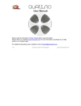
User Manual Please read this manual carefully before using the Phoenix Octopus For additional help and updates, refer to our website www.phnxaudio.com To contact Phoenix Audio for support, please send a detailed e-mail to [email protected] Table of Contents Introduction…………………..….…………………2 Specifications………………………………………2 Product Concept …………………………………..3 Installing………………….…………………………5 Setup Wizard …………………………….. ………11 Setup Utility ……………………………………….15 Phoenix Audio Technologies 1 www.phnxaudio.com Introduction The Phoenix Octopus Conferencing Mixer utilizes Beamforming microphone array technology, provides unlimited daisy chain capability, and allows for multiple connectivity options all in a single, easy to install box. The Octopus gives the ability to mount microphones and speakers anywhere in the room (ceilings, walls, and table tops). It comes standard with USB and RCA connectors for VoIP and Video Codec connectivity, with the option of adding a PSTN (analog telephone) interface or a digital telephone interface. The Phoenix Octopus can be ordered with an optional 40 watt, 4-output amplifier for powering speakers. Each Octopus unit has four microphone inputs, each of which can be set for Mic (3V or 24V Phantom available). Each of the four inputs can be set to participate in the Beamforming process, or designated as a unique Auxiliary or Sound Reinforcement channel. The Octopus utilizes Phoenix Audio’s proprietary Beamforming algorithm. It performs echo cancellation, noise suppression, and dereverb filtering to rid the send signal of unwanted echo and reflected sounds. Specifications Inputs Designation: Microphone (mixer inputs), Auxiliary, Sound reinforcement Number of inputs: 4 per unit Phantom: user selectable: 3V, 24V or none (for Line inputs) Connectors: XLR Input Impedance (load): 3V Phantom: 2K ohm 24V Phantom: 590 Ohm No Phantom: 2K ohm Maximum input level: 1.8V/Gain Gain: user selectable: 0dB to 42dB in 6dB steps Frequency response: 20 Hz - 16 KHz Audio Out Connectors: RCA and XLR (the XLR is re-assigned as LinkUp when the unit is configured as Slave) Level: Line or Mic level (user selectable) For Line level: 1.8Vpp Max Phoenix Audio Technologies 2 For Mic level: 90mVpp Max LinkUp level: Line (1.8Vpp fixed) Impedance: 25 ohm Frequency response: 20 Hz - 16 KHz Audio (Far End) In Connector: RCA Impedance: 100K ohm Level: 1.8Vpp Far-End (Speaker) out Connector: 2pin terminal block Impedance: 25 ohm Level: 1.8Vpp Max Com Port: RS232 – protocol available upon request Power: 5V, 200mAmp (through the USB connector) www.phnxaudio.com either Slaves or a Master. The Master communicates with the conferencing unit (VoIP, Video Codec or Telephone) and receives, into its microphone inputs, the output of Slave units. Each of the Slaves can act as a lower hierarchy master and as such receive into its microphone inputs lower level Salves. The Matrix microphones are connected to the lowest level Salves. The following guidelines apply to the Multi Unit connection: A Master unit will be configured at the top of the chain; it will be connected to the communication line. Its inputs can be assigned as unique channels (SR or Aux) or Slave’s output. The Slaves that are connected to this Master can be assigned as mid-level masters and be fed from lower level Slaves. All the inputs of a Slave unit are of similar nature. More specifically – if one of the inputs is designated as Slave’s output then all the inputs will be assigned the same. The Matrix microphone will be connected to the lowest level Slaves. When all the units are connected the output of the whole setup equals the result of the automatic Beamforming process of all the microphones + the SR channels + the Aux channels. Product Concept The Octopus is designed for easy installation and setup, therefore the microphones are mixed automatically utilizing a sophisticated Beamforming Mixer algorithm. This means that the octopus will assess the signals picked up by all the microphones, and decide, instantaneously, which one will take part in the mixing and with what level of emphasis (weight). At any point any number of microphones can take part in the mixing, from a single microphone to all of them – the unit will make the assessment automatically and will control the mixing parameters. The user does not have to (and actually cannot) control the process. The microphones that are selected to take part in this automatic process are referred to in this document as Matrix microphones In addition to the Matrix microphones, the user can define up to four unique input channels; each of them can be designated as “Sound Reinforcement” (referred heron as SR) channel or “Auxiliary” (referred hereon as Aux). Both types of unique channels will be summed with the Beamforming output; they will also be summed with the incoming “far-end” signal and played through the local speakers (the user can control the level of local playback for each unique channel separately and independent from the far-end playback level). These channels can be used for local amplification of a podium microphone (SR channel) or local amplification of a pre-recorded presentation (Aux). The difference between these two types is in the way the echo and feedback cancellers treat them. This Layered Star expansion configuration is explained in details in the following chapters. Each Octopus unit can manage up to four input channels, but is capable to connect to other Octopus units for an unlimited expansion. For the expanded setup units are configured as Phoenix Audio Technologies 3 www.phnxaudio.com Panels Overview Front panel includes: One/Off switch Power LED indicator ¼” audio Monitor jack – this jack is used for setting and testing the unit. During setup (with the setup wizard) the microphone inputs and the system output will be assigned to this jack (depending on the setting phase – see details in the Setup Wizard chapter). Optional Telephone interface – see details in the next chapters Back panel includes Four input XLR connectors LED indicator (next to each of the inputs) indicating when Phantom power is on. SPK In - RCA jack for the far-end signal (connected to the CODEC’s speaker’s out connector). Audio Out - RCA jack for system out signal (connected to the CODEC’s input’s connector). XLR jack for either Link Up connection (when unit is assigned as a Slave) or system output (similar to the Audio Out RCA jack). Terminal Block (2 Pin) for speaker out (non-powered). Com Port - RS232 communication with a control panel (AMX, Crestron or other). USB jack for USB computer connection. The USB is used for control, audio data (in and out) and power (does not power the “powered speakers”). Optional Power Module panel including an AC jack (220V or 110V) and four speaker’s spring connection. Optional Telephone Interface Optional powered speakers’ panel Phoenix Audio Technologies 4 www.phnxaudio.com done with the setup wizard and is explained in details in the next chapter). Connect your inputs to the Mic inputs in the back panel using standard XLR connections (see diagram below). Designing & Installing the Octopus System For optimal performance we recommend the following steps while setting up the Octopus system: 1) Making all the necessary connections, including the microphones, speakers, communication interface(s) and controls. 2) Using our setup wizard to configure the unit(s), set, tune, and test the microphones and speakers’ connections 3) Using our audio setup utility for further settings If your setup includes more than four inputs you need to use several units (depending on the number of inputs) and connect them in our unique “Layered Star” expansion configuration. In this configuration the Matrix microphones (unlike SR or Aux input) are connected to lower hierarchy level units which will be configured as Slaves - up to four microphones per Slave (so if you have 5-8 Matrix inputs you need 2 ‘lower level’ Slaves, 9-12 inputs you need 3 ‘lower level’ Slaves, and so on). The following chapters will walk you through these three steps. Up to four Slaves are connected to either a mid-level Slave or a Master unit using a standard XLR to XLR cable (not supplied) - the Link Up of the lower level unit is connected to one of the microphone inputs of the higher level unit. Note that with two layers (one Master and up to four Slaves) you can connect up to 16 Matrix microphones (see diagram below). Making the Connections Microphones / Inputs If your setup includes up to four inputs (including Matrix microphones as well as SR and Aux inputs) you should configure the unit as a “Stand Alone” unit (configuration is Stand Alone configuration with 3 Matrix microphones and 1 podium microphone 5 Link Up In4 In3 In2 In1 Phoenix Audio Technologies www.phnxaudio.com Two layer configuration with 12 matrix microphones and 1 podium microphone Three Slave units and one Master Link Up In4 In3 In2 In1 Link Up In4 In3 In2 In1 Link Up In4 In3 In2 In1 Link Up In4 In3 In2 In1 If your setup requires more inputs you need to create additional layers; connect the lower level Salves to mid-level Slaves (Link Up to Mic input) and so on. At the top of the hierarchy will be a Master unit. Connect the unique inputs (SR and or Aux) to the Master unit. See an example of a three layer configuration below. Phoenix Audio Technologies 6 www.phnxaudio.com Three layer configuration with 20 matrix microphones, 1 podium microphone and 1 auxiliary input (tape) Five Slave units and three Masters Link Up In4 In3 Link Up In4 In3 In1 In2 Link Up Link Up In4 In3 In2 In1 7 In2 Link Up In4 In1 In4 In3 Link Up In3 Link Up In4 In2 In4 In3 In2 In3 In2 In1 In2 In1 In1 In1 Link Up In4 In3 In2 In1 Phoenix Audio Technologies www.phnxaudio.com speakers’ output into the Octopus ‘SPK In’ jack (black RCA). Speakers The loudspeaker signal can come from different communication sources. It could come from the far-end of the IP link (through the USB communication), through the far-end of the telephone line (digital or analog), it could come from the far-end of the Video Codec system (through its speakers’ RCA jack), or any combination of the above. In order to ensure proper Echo Cancelling performance, please follow the instructions herein. Option 2: Speakers Connection Split Video Codec When connected to a Video Codec system (and only Video Codec) the user can select one of three configurations: 1) Connect the Codec speakers’ output to the Octopus ‘SPK In’ jack (black RCA). Connect the room’s speakers to the Octopus ‘SPK Out’ connector(s). Octopus Option 1: Speakers Connected through the Octopus 3) Alternatively, when using TV monitor’s speakers, you could connect the Video Codec speakers’ output to the TV monitor, and connect the “external speakers” on the TV monitor to the Octopus’s ‘SPK In’ jack. Video Codec Option 3: Using TV Monitor Speakers Octopus Video Codec 2) Connect the Codec speakers’ output directly to the room’s speakers. Connect, in parallel, the Codec Phoenix Audio Technologies Octopus 8 www.phnxaudio.com If the speaker source is not solely VC it is required that the room speakers be fed through the Octopus. The USB and telephone far-end signals are connected directly to the Octopus. The Video Codec signal should be connected into the ‘SPK In’ connector. All these signals will be summed together and send to the Octopus’s SKR Out jack work with any OS for data communication (including MAC and Linux). However the controls, including the setup wizard and audio utility are only available on Windows OS. Analog telephone (PSTN) – the PSTN interface (optional) is intended to be used with analog telephone lines (Public Switched Telephone Network). It will connect the Octopus directly to the line (the telephone jack in the wall) through a standard telephone cable (the same one used to connect the telephone to the line). One side of the cable should be plugged into the telephone jack in the wall, the other side into the wider jack of the interface module (on the left). The standard ‘SPK Out’ connector (2 pin terminal block) supplies non-amplified, Line Level signal. The optional Power Amplifier Module (PAM) can power four loudspeakers and drive each one of them with 10 Watts signal into an 8 Ohm speaker. Note that in order to enjoy the amplified outputs the units has to be powered directly through the AC jack (available with the PAM). If the Octopus is powered through the USB jack the power amplifier will not function, even if the module is available and connected. The right jack (narrower) is used to connect a dialer to the Octopus (Phoenix offers an external dialer module). Alternatively the user can use a soft dialer available for a free download on our website, or use a third-party controller (AMX, Crestron or other) that supports our dialing protocol. The dialer (soft or hard) is used to off-hook the system, dial and on-hook it again (just like any telephone). Communication Link and System Output The Octopus can connect to a Video Codec through the RCA jacks (standard), an IP link through the USB jack (standard), and to a telephone (digital or analog) through and optional telephone interface. Video Codec – connect the VC speakers signal into the Octopus SPK In jack (black RCA) – see Speakers connection recommendation above. Connect the Octopus output (red RCA) into the VC audio input jack. You can also use the Link Up jack as a balanced output for VC systems that prefers this type of input. The user can select the output level to be either Line level of Mic level (on both the red RCA and the XLR balanced output). Digital telephone (DTI) – the DTI interface (optional) is essentially an analog connection that is designed to connect to a digital telephone through this telephone’s headset jack. Since most (if not all) digital telephones come with an RJ9 jack for the headset connection, the DTI interface has an RJ9 jack as well, and is provided with two RJ9-RJ9 cables that will work with different telephone systems. USB – simply connect the Octopus to a USB port on your computer (USB cable supplied). Note that the Octopus can Phoenix Audio Technologies 9 www.phnxaudio.com Note: the Octopus can communicate in parallel with the VC, IP link (USB), and either a PSTN or DTI the telephone interface (only one telephone interface can be integrated into the Octopus). Two of these three links can communicate with each other (through the Octopus). The user can select which two and set their volume levels separately. More details in the following chapters. In addition the interface includes a double-switch with four positions that is used to set up output level for different telephone systems. The user initiates the call through the telephone and then switches to the Octopus by pushing the Headset button on the telephone (just like using headset with the telephone). The factory setting for the telephone switches delivers the lowest level output (see gain diagram below). We recommend that when tuning the unit you should start with this lowest level and increase the gain until the other side complains that the signal is distorted. Note that these switches affect the output (signal that goes to the other side and not the signal coming in). Phoenix Audio Technologies 10 www.phnxaudio.com Setup Wizard The Setup Wizard is used to configure the type of unit, the input settings (type, level, and phantom selection) and setup the output level. Additional settings are available through the audio setup utility. Those include 3-way settings, color (frequency response) settings, and more, and will be detailed in the next chapter. Setting the units is performed one unit at a time. Plug your Laptop to the USB port of the unit being set and run the Setup Wizard software. We recommend that you start with the lower ranked units (to which the Matrix microphones are connected) and go up the ladder. Please note that in order for the Beamforming algorithm to perform properly all the microphones participating in the matrix have to have the same sensitivity. Therefore when you setup any microphone, all the microphones connected to the same unit will automatically be set to the same sensitivity level. Furthermore – in a Multi-Unit setting, when you set the next Slave unit the software remembers the last microphone setup and will recommend that you use the same parameters (and will copy / paste them for you). If you change the settings of a microphone along the way the software will recommend that you go back to previously set Slave units and reset them with the new level. If the unit is mid rank unit (not the lowest Slave and not the Master) then it should be set to be a Slave. The following paragraphs detail the setup steps for each of the Octopus’s types. Since some of the setting screens in various types are similar, the Stand Alone setup is the most detailed and we recommend that you read through it even if you are not setting your system as such. Setting a Stand Alone unit SA units include all the connections (inputs, outputs and farend) therefore you will be guided though the setting of the loudspeakers’ volume, the microphones and the output. The opening screen of the Wizard program sets up the unit type. You can select one of three types: Stand Alone, Master or Slave. If your unit has previously been programmed the wizard program tells you which type the unit is set to, and allows you to either keep it or change it. Phoenix Audio Technologies In the first step you are setting the room’s loudspeakers volume. You can play either a music file or speech and setup the speakers’ volume to the wanted level. 11 www.phnxaudio.com (meaning Matrix microphone), SR channel, or Aux channel. You can select whether the input requires a Phantom supply, and if yes whether it is 3V or 24V. You can then increase/decrease the input level, monitor the signal on the scope (on the right hand side), record the signal, play it back and save it into a file. During the entire session the microphone inputs are routed to the Monitor jack (front panel) so that you can listen to it in real time using a set of headphones. When setting the loudspeakers’ volume you should keep in mind that you need to avoid saturating the microphones with the speakers’ signal. Each time you click Next the program jumps to the next input. You can move forward / backward using the Next and Back buttons or just click on the relevant input. Remember – when you change the settings of a microphone the same setup will apply to all the microphone channels. If this is not the first Slave you are programming and you change the setting the program will recommend that you go back to the other Slaves and re-set their inputs to match the lasted setup. If you designate the inputs to be either SR or Aux channels you will have the option to set the level of the local sound – this slider controls the level in which this channel will be played through the room’s speakers. In addition you can set the Analog Gain of this channel which sets the level in which this channel will be summed up with the Beamforming output. The next step guides you through the setting of the four inputs of the units; each can be set as a microphone Phoenix Audio Technologies 12 www.phnxaudio.com You can record the output, playback the recording and save it into a file. You can also listen to the output in real time through the Monitor jack using a set of headphones. Note: when the setting of the unit is finished the output of that unit will keep being routed to the Monitor jack so that you can simply listen to all the units one at a time. The Output slider controls the output level of all the different system’s outputs at the same time, including USB, VC and telephone (when applicable). The output levels can be controlled individually with the Audio Setup Utility. Slave When all the inputs are set the program will guide you to the output level setup. You can choose between Line-level output and Mic-level output. Use the slider to set the optimal level. The definition of the Line-level and Mic-level (as they appear in the spec sheet) apply to the slider position at the maximum level. A Slave unit, by definition, is not connected to the room’s speakers or to the communication cannel. Therefore the only thing you set is the inputs. The Input Setup screen is similar to the Stand Alone units but it does not allow you to designate a channel as Aux or SR (these channels can only be connected to a Master unit). Please refer to the Stand Alone setting chapter for detailed Phoenix Audio Technologies 13 www.phnxaudio.com explanation on how to set the input levels. Master The first screen in setting a Master unit is setting the speakers’ volume, which is similar to the first screen of a Stand Alone unit; please refer to the Stand Alone setting chapter for details. The next screen is the input setting. A Master unit, by definition, is not connected to Matrix microphones; therefore the inputs selection is limited to Slave, SR, and Aux. See the details on setting SR and Aux channels in the Stand Alone chapter. Once the inputs are set, the program will take you to the output level setting. This screen is similar to the output setup screen of the Stand Alone unit – please refer that chapter for details. Phoenix Audio Technologies 14 www.phnxaudio.com the Tel<->PC option, the VoIP and the Tel participants will hear each other and will not hear the VC participants. However the VC participant can still hear the Octopus and the Octopus can hear it. Additional Settings - Audio Setup Utility The Audio setup utility can help you set some additional parameters. These setting apply only to a Stand Alone or Master unit. The default setting is VC<->PC since these two are available in the basic module (while the Tel is optional). 3-Way setting The type of 3-way is selected in the Options menu of the Audio Setup utility. The Octopus can communicate with up to 3 different sources at the same time: the VoIP (through the USB port), Video Codec (through the RCA jack), and the optional telephone interface (PSTN or DTI). As such, all three participants will hear the Octopus, and the Octopus will hear all of them simultaneously. Individual Audio Setting The transmit (output) and receive (speakers) levels which were set by the Wizard applied to all three interfaces at the same time (and same level). The Audio Setup Utility allows you to control the levels individually so that the output level, for example, going into the Telephone line can be set do a different level from the signal going into the VoIP. This allows you to balance the system with a better accuracy. However, only two of the three can hear each other, and the user can select which of the two. The three options are: Tel<->PC, VC<->PC, VC<->Tel. If, for example we selected Phoenix Audio Technologies 15 www.phnxaudio.com The separate volume sliders are available when you select the Advanced mode, and the sliders change their functionality depending on the selection of the 3-way (if the selection was VC<->PC then the sliders will control the VC and the PC volumes). In addition, you can set the Bridge level – i.e. the level of signal going from one of the 3-way participants to the other and back. If you are experiencing difficulty please send an email to Tech Support at [email protected] or call our technical support department (telephone numbers available on our support page at www.phnxaudio.com. Color Filter You can select to apply a color filter on the output or input (speaker’s signal). Select the option from the Audio Utility menu and select a filter from a list of 8 pre-set filters. Phoenix Audio Technologies 16 www.phnxaudio.com