1
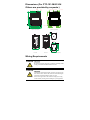
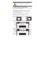
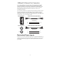
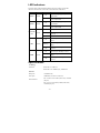
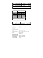
Moxa Industrial Media Converter
PTC-101
Hardware Installation Guide
Second Edition, February 2010
© 2010 Moxa Inc. All rights reserved.
Reproduction without permission is prohibited.
Fl.4, No.135, Lane 235, Pao-Chiao Rd. Shing Tien City, Taipei, Taiwan,
R.O.C.
TEL: +886-2-8919-1230
P/N: 1802001016011
Overview
Moxa Industrial Media Converter, which is specially designed for reliable and
stable operation in harsh industrial environments, provides industrial grade
media conversion between 10/100BaseT(X) and 100BaseFX. PTC-101’s
reliable industrial design is excellent for keeping your industrial automation
applications running continuously, and comes with a relay output warning
alarm to help prevent damages and losses.
This product has a wide operating temperature range, from -40 to 85°C, and is
designed to withstand a high degree of vibration and shock. The rugged
hardware design makes PTC-101 perfect for ensuring that your Ethernet
equipment can withstand critical industrial applications, such as in hazardous
locations, and complies with FCC, UL, and CE standards.
Package Checklist
Moxa Industrial Media Converter is shipped with the following items. If any of
these items is missing or damaged, please contact your customer service
representative for assistance.
y Moxa Industrial Media Converter
y Hardware Installation Guide
y Moxa Product Warranty booklet
Features
y Supports 10/100Base-TX auto-negotiation and auto-MDI/MDI-X.
y Multi mode, single mode with SC or, ST, or LC fiber connector available.
y Supports Link Fault Pass-Through.
y Power failure by relay output (LV model only).
y Redundant dual VDC power inputs.
y -40 to 85°C operating temperature range.
y Integrated high-reliability power supply eliminates the need for external
power transformer.
-2-
Panel Layout of PTC-101 Series
Top Panel View
2
Terminal block for power
3.
3
3
4
4
Grounding screw
2.
input
1
2
1
1.
Front Panel View
(PTC-101-M-SC-HV)
Front Panel View
(PTC-101-M-ST- LV)
4.
DIP switch
5.
Power input PWR LED
6.
Fiber Link/Active LED
7.
100BaseFX Port
(ST/SC/LC connector)
8.
5
5
6
6
7
7
9
10
8
11
Heat dissipation vents
and relay output
9
8
10
11
Rear Panel View
Rear Panel View
12
12
-3-
10/100BaseT(X)
9.
TP port 10 Mbps LED
10.
TP port 100 Mbps LED
11.
Model Name
12.
DIN-Rail mounting kit
Dimensions (For PTC-101-M-SC-HV.
Others are provided by requests.)
67.4 mm (2.65 in)
15 mm
(0.59 in)
42.4 mm (1.67 in) 40 mm (1.57 in)
19 mm
(0.75 in)
19 mm (0.75 in)
144.15 mm (5.68 in)
144.15 mm (5.68 in)
101.4 mm (3.99 in)
111.4 mm (4.39 in)
123.46 mm (4.86 in)
101.4 mm (3.99 in)
12.06 mm (0.47 in)
111.4 mm (4.39 in)
123.46 mm (4.86 in)
Side View (HV Models)
Side View (LV Models)
26.2 mm
(1.03 in)
135.1 mm (5.32 in)
30.5 mm
(1.2 in)
26.06 mm
(1.03 in)
66.65 mm (2.62 in)
67 mm (2.64 in)
54 mm (2.13 in)
PTC-101-M-SC-HV
34 mm
(1.34 in)
51.6 mm (2.03 in)
Front View
Rear View
Panel Mounting Kit (Optional)
Wiring Requirements
ATTENTION
ATTENTION
Safety First!
Be sure to disconnect the power cord before installing and/or
wiring your Moxa Industrial Media Converter.
Safety First!
Calculate the maximum possible current in each power wire
and common wire. Observe all electrical codes dictating the
maximum current allowable for each wire size.
If the current goes above the maximum ratings, the wiring
could overheat, causing serious damage to your equipment.
-4-
You should also pay attention to the following points:
y Use separate paths to route wiring for power and devices. If power wiring
and device wiring paths must cross, make sure the wires are perpendicular
at the intersection point.
NOTE: Do not run signal or communications wiring and power wiring in
the same wire conduit. To avoid interference, wires with different signal
characteristics should be routed separately.
y You can use the type of signal transmitted through a wire to determine
which wires should be kept separate. The rule of thumb is that wiring that
shares similar electrical characteristics can be bundled together.
y Keep input wiring and output wiring separated.
y It is strongly advised that you label wiring to all devices in the system when
necessary.
Grounding Moxa Industrial Media
Converter
Grounding and wire routing help limit the effects of noise due to
electromagnetic interference (EMI). Run the ground connection from the
ground screw to the grounding surface prior to connecting devices.
ATTENTION
This product is intended to be mounted to a well-grounded
mounting surface such as a metal panel.
Wiring the Redundant Power Inputs
for PTC-101-LV series
The top five contacts of the 8-contact terminal block connector on the
PTC-101-LV’s top panel are used for the PTC-101-LV’s two DC inputs. Top
and front views of one of the terminal block connectors are shown here.
STEP 1: Insert the negative/positive DC wires
into the V-/V+ terminals.
Top View
STEP 2: To keep the DC wires from pulling
loose, use a small flat-blade screwdriver to
tighten the wire-clamp screws on the front of
the terminal block connector.
Front View
STEP 3: Insert the plastic terminal block
connector prongs into the terminal block
receptor, which is located on the
PTC-101-LV’s top panel.
-5-
ATTENTION
Before connecting PTC-101-LV to the DC power inputs,
make sure the DC power source voltage is stable.
Communication Connections
PTC-101 models have one 10/100BaseT(X) Ethernet port, and one 100BaseFX
(SC, ST, or LC type connector) fiber port.
10/100BaseT(X) Ethernet Port Connection
The 10/100BaseT(X) ports located on PTC-101’s front panel are used to
connect to Ethernet-enabled devices.
Below we show pinouts for both MDI (NIC-type) ports and MDI-X
(HUB/Switch-type) ports, and also show cable wiring diagrams for
straight-through and cross-over Ethernet cables.
RJ45 (8-pin, MDI) Port Pinouts
Pin
Signal
1
2
3
6
Tx+
TxRx+
Rx-
1
RJ45 (8-pin, MDI-X) Port Pinouts
Pin
Signal
1
2
3
6
Rx+
RxTx+
Tx-
8
1
8
RJ45 (8-pin) to RJ45 (8-pin) Straight-Through Cable Wiring
Straight-Through Cable
Switch Port
RJ45
Connector
Tx+
TxRx+
Rx-
NIC Port
RJ45 Plug Pin 1
RJ45
Connector
Cable Wiring
3
6
1
2
3
6
1
2
Rx+
RxTx+
Tx-
RJ45 (8-pin) to RJ45 (8-pin) Cross-Over Cable Wiring
Cross-Over Cable
Switch Port
(NIC Port)
RJ45 Plug Pin 1
RJ45
Connector
(Rx+)
(Rx-)
(Tx+)
(Tx-)
Tx+
TxRx+
Rx-
Switch Port
(NIC Port)
RJ45
Connector
Cable Wiring
3
6
1
2
1
2
3
6
-6-
Rx+
RxTx+
Tx-
(Tx+)
(Tx-)
(Rx+)
(Rx-)
100BaseFX Ethernet Port Connection
The concept behind the SC port and cable is quite straightforward. Suppose
you are connecting devices I and II. Contrary to electrical signals, optical
signals do not require a circuit in order to transmit data. Consequently, one of
the optical lines is used to transmit data from device I to device II, and the
other optical line is used transmit data from device II to device I, for
full-duplex transmission.
All you need to remember is to connect the Tx (transmit) port of device I to the
Rx (receive) port of device II, and the Rx (receive) port of device I to the Tx
(transmit) port of device II. If you are making your own cable, we suggest
labeling the two sides of the same line with the same letter (A-to-A and B-to-B,
as shown below, or A1-to-A2 and B1-to-B2).
SC-Port Pinouts
SC-Port to SC-Port Cable Wiring
A
A
B
B
Tx
Cable Wiring
A
B
Rx
ST-Port Pinouts
A
B
ST-Port to ST-Port Cable Wiring
A
A
Tx
B
B
Cable Wiring
Rx
A
B
A
B
Redundant Power Inputs
For PTC-101-LV series, both power inputs can be connected simultaneously to
live DC power sources. If one power source fails, the other live source acts as a
backup, and automatically supplies all of Moxa Industrial Media Converter’s
power needs.
-7-
DIP Switch Setting
ON
1
DIP
2
3 4
5
DIP No.
Function
ON
OFF
1
Auto Negotiation
Enable
Disable
“ON”: Enables “Auto Negotiation” function, the speed and duplex states for
each port link segment are automatically configured using the highest
performance interoperation mode.
“OFF”: Disables “Auto Negotiation” function, the speed and duplex states
depend on the manual setting configuration.
2
Force TP Speed
100Mbps
10Mbps
(Only when Auto Negotiation is disabled)
“ON”: Forces 100Mbps on Ethernet port.
“OFF”: Forces 10Mbps on Ethernet port.
3
Force TP Duplex
Full Duplex
(Only when Auto Negotiation is disabled)
Half Duplex
“ON”: Forces Full Duplex on Ethernet port.
“OFF”: Forces Half Duplex on Ethernet port.
4
Link Fault Pass Through
Enable
Disable
“ON”: Enables “Link Fault Pass Through”, the link status on the TX port will
inform the FX port of the same device and vice versa.
“OFF”: Disables “Link Fault Pass Through”, the link status on the TX port
will not inform the FX port.
5
Operating Mode
Store-and-Forward Pass Through
“ON”: Selects “Store-and-Forward” mode, begins to forward a packet to a
destination port after an entire packet is received. The latency depends
on the packet length.
“OFF”: Selects “Pass Through” mode, operates with the minimum latency.
Both transceivers are interconnected via internal MIIs and the
internal switch engine and data buffer are not used.
Note: With “Pass Through” mode enabled, the Ethernet port and fiber port
should transmit at 100 Mbps, which is equivalent to full duplex mode.
Default DIP settings are all at ON position.
ATTENTION
After changing the DIP switch setting, you will need to
power off and then power on the PTC-101 to activate the
new setting.
-8-
LED Indicators
The front panel of Moxa Industrial Media Converter contains several LED
indicators. The function of each LED is described in the table below.
LED
PWR1
PWR2
Fiber/Link
/Act
10M
100M
Color
State
On
Off
Power is not being supplied to
power input PWR1
On
Power is being supplied to power
input PWR2
Off
Power is not being supplied to
power input PWR2
On
Fiber port is active
Green
Green
Green
Yellow
Green
Description
Power is being supplied to power
input PWR1
Blinking
Data is being transmitted or
received.
Off
Fiber is inactive
On
Ethernet port 100 Mbps link is
active
Blinking
Data is being transmitted at 10
Mbps
Off
Ethernet port 10 Mbps link is
inactive
On
Ethernet port 100 Mbps is active
Blinking
Data is being transmitted at 100
Mbps
Off
Ethernet port 100 Mbps link is
inactive
Specifications
Technology
Standards
IEEE 802.3 for 10BaseT
IEEE 802.3u for 100BaseT(X), 100BaseFX
Interface
RJ45 ports
10/100BaseT(X)
Fiber ports
100BaseFX (SC/ST/LC connectors)
LED Indicators
PTC-101-HV series: PWR1, Fiber Link, 10/100M
(TP port)
PTC-101-LV series: PWR1, PWR2, Fiber Link,
10/100M (TP port)
-9-
Dip Switches:
Dip No.
Function
ON
1
Auto Negotiation
Enable
2
Force TP Speed
100 Mbps
3
Force TP Duplex
Full Duplex
4
Link Fault Pass Throuth
Enable
5
Operating Mode
Store-and-Forward
Default DIP settings are all at ON position.
Alarm Contact
OFF
Disable
10 Mbps
Half Duplex
Disable
Pass Through
One relay output with current carrying capacity of
1 A @ 24 VDC
Optical Fiber:
100BaseFX
Multi-mode
Single-mode
1300 nm
1310 nm
Wavelength
-10 dBm
0 dBm
Max. TX
-20 dBm
-5 dBm
Min. TX
-32 dBm
-34 dBm
RX Sensitivity
12 dB
29 dB
Link Budget
5 kma
Typical Distance
40 kmc
b
4 km
-6 dBm
-3 dBm
Saturation
a. 50/125 μm, 800 MHz*km fiber optic cable
b. 62.5/125 μm, 500 MHz*km fiber optic cable
c. 9/125 μm, 3.5 PS/(nm*km) fiber optic cable
Power Requirements
Input Voltage:
Power Supply Type
LV-DC 20 VDC ~ 72 VDC
HV-AC 85 VAC ~ 264 VAC
HV-DC 88 VDC ~ 300 VDC
Power Consumption
170mA@20VDC
73mA@85VAC
47mA@88VDC
Fuse Rating
3.15A(T) 2
3.15A(T) 2
3.15A(T) 2
Connection
Removable Terminal Block
Overload Current
Protection
1.6 A (protects against two signals shorted
together)
Reverse Polarity
Protection
Present
Physical Characteristics
Housing
Aluminum, IP30 protection
Dimensions (W x H x D)
122.5 x 90 x 20 mm (4.82 x 3.54 x 0.79 in)
Weight
Product only: 690 g
Packaged: 875 g
Environmental Limits
Operating Temperature
-40 to 85oC (-40 to 185oF)
Storage Temperature
-40 to 85 oC (-40 to 185 oF)
Operating Humidity
5 to 90%
- 10 -
Regulatory Approvals
Safety
UL 60950-1
EMI
FCC Part 15, CISPR (EN55022) class A
EMS
EN61000-4-2 Edition 1.2: 2001-04 (Level 4)
EN61000-4-3: 1995+A1: 2001
IEC 61000-4-3: 2002+A1: 2002 (Level 3)
EN61000-4-4: 2004 (Level 4)
EN61000-4-5: 2001-04 (Level 4)
EN61000-4-6: 2004-11 (Level 3)
EN61000-4-8: 2001-03 (Level 5)
EN61000-4-11: 2004-03 (Criteria B)
Power Automation
IEC 61850-3, IEEE 1613
Rail Traffic
EN50155/EN50121-4
Warranty
5 years
Details: See www.moxa.com/warranty
Technical Support Contact Information
www.moxa.com/support
Moxa Americas:
Toll-free: 1-888-669-2872
Tel:
+1-714-528-6777
Fax:
+1-714-528-6778
Moxa China (Shanghai office):
Toll-free: 800-820-5036
Tel:
+86-21-5258-9955
Fax:
+86-10-6872-3958
Moxa Europe:
Tel:
+49-89-3 70 03 99-0
Fax:
+49-89-3 70 03 99-99
Moxa Asia-Pacific:
Tel:
+886-2-8919-1230
Fax:
+886-2-8919-1231
- 11 -