1
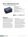
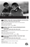
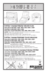
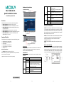
Hardware Introduction NPort 5600-8-DTL Top and Rear Views Quick Installation Guide InUse (P1 to P8) First Edition, March 2011 Overview TX/RX (P1 to P8) The NPort 5600-8-DTL series includes the following models: • • • • • • NPort 5610-8-DTL: 8 ports, RS-232, 0 to 60°C NPort 5650-8-DTL: 8 ports, RS-232/422/485, 0 to 60°C NPort 5650I-8-DTL: 8 ports, RS-232/422/485, 0 to 60°C, 2KV optical isolation. NPort 5610-8-DTL-T: 8 ports, RS-232, -40 to 75°C NPort 5650-8-DTL-T: 8 ports, RS-232/422/485, -40 to 75°C NPort 5650I-8-DTL-T: 8 ports, RS-232/422/485, 2KV optical isolation, -40 to 75°C Front View STEP 2: Use an Ethernet cable to connect the NPort 5600-8-DTL to a network hub or switch. You can also connect directly to your computer’s Ethernet port, which is convenient for initial configuration or testing. STEP 3: Connect the NPort 5600-8-DTL’s serial port to a serial device. Wall or Cabinet Mounting Reset Button Optional Accessories* • Steady: Network is connected; no data is being transmitted. Blinking: Network is connected; data is being transmitted. off Ethernet cable is disconnected or has a short. green Serial port has been opened by server side software. off Serial port is not currently opened by server side software. green (Tx) Serial device is transmitting data. orange (Rx) Serial device is receiving data. off No data is flowing to or from the serial port. STEP 1: After removing the NPort 5600-8-DTL from the box, place it on a desktop or other horizontal surface. Connect the 12-48 VDC power adaptor to the NPort 5600-8-DTL’s power input when using an AC power source, or connect the NPort 5600-8-DTL’s terminal block directly to a DC power source. The NPort 5600-8-DTL package should contain the following items: NPort 5600-8-DTL device server Wall mounting and DIN-Rail kits Stick-on pads Documentation and software CD Quick installation guide (printed) Warranty card green Hardware Installation Package Checklist • • • • • • Link DK-35A: DIN-Rail mounting kit (35 mm) Note: Please notify your sales representative if any of the above items are missing or damaged. *Optional Accessories can be ordered separately. Use a pointed object to hold the reset button down for at least five seconds to load the factory defaults. Release the reset button when the Ready LED stops blinking. LED Indicators The NPort 5600-8-DTL comes with two metal attachment plates to allow installation on a wall or the inside of a cabinet. First, attach the brackets to the back of the NPort with screws. Next, mount the unit on a wall or cabinet with screws. Screws should be less than 6.0 mm in head diameter, and less than 3.5 mm in shaft diameter. The LED indicators on the top panel are used to display the status as follows: Name PWR Ready Color red off green Fault off red off Function Power is on. Power is off. Steady: NPort is operational Blinking: NPort is responding to NPort Administrator “Locate” function or NPort is resetting to factory default Power is off or fault condition exists. IP conflict or DHCP or BOOTP server did not respond properly. No fault condition detected. P/N: 1802056000010 –1– –2– –3– DIN-Rail Mounting DIN-Rail attachments can be purchased separately to attach the product to a DIN-Rail. The DIN-Rail attachments should be oriented with the metal springs on top. Standard Attachment DK-35A Attachment Specifications LAN Ethernet Ports: 10/100 Mbps (RJ45) Protection: Built-in 1.5 KV magnetic isolation Serial Interface RS-232: NPort 5610-8-DTL RS-232/422/485: NPort 5650-8-DTL, 5650I-8-DTL Serial Ports: 8 (DB9-M connectors) Isolation: 2 KV isolation (NPort 5650I-8-DTL) Serial Signals RS-232: TxD, RxD, RTS, CTS, DTR, DSR, DCD, GND RS-422: Tx+, Tx-, Rx+, Rx-, GND RS-485 (2-wire): Data+, Data-, GND RS-485 (4-wire): Tx+, Tx-, Rx+, Rx-, GND Serial Line Protection: 15 KV ESD for all signals RS-485 Data Direction: ADDC™ (Automatic Data Direction Control) Serial Communication Parameters Software Installation Information To install NPort Administration Suite, insert the NPort Document & Software CD into your PC’s CD-ROM drive. Locate and run the setup program and follow the on-screen instructions. The setup program will be named Npadm_Setup_[Version]_Build_[DateTime].exe (e.g., “Npadm _Setup_Ver1.16_Build_11021010.exe”). Refer to the NPort 5600-8-DTL User’s Manual for more details. Pin Assignments DB9 Male Ports Pin RS-232 1 2 3 4 5 6 7 8 9 DCD RxD TxD DTR GND DSR RTS CTS – RS-422/ RS-485-4W TxD-(A) TxD+(B) RxD+(B) RxD-(A) GND – – – – RS-485-2W – Data+(B) Data-(A) GND – – – – Parity: None, Even, Odd, Space, Mark Data Bits: 5, 6, 7, 8 Stop Bit(s): 1, 1.5, 2 Flow Control: RTS/CTS, DSR/DTR (for RS-232 only), XON/XOFF Transmission Speed: 50 bps to 921.6 Kbps Power Requirements Power Input: 12 to 48 VDC Physical Characteristics Operating Temperature: Standard Models: 0 to 60°C (32 to 140°F) Wide Temp. Models: -40 to 75°C (-40 to 167°F) Storage Temperature: -40 to 85°C (-40 to 185°F) Operating Humidity: 5 to 95% RH Material: SECC sheet metal (0.8 mm) Dimensions: Without ears: 197 × 44 × 125 mm With ears: 229 × 46 × 125 mm With DIN-Rail kit: 197 × 52.8 × 125 mm Certifications Regulatory Approvals: FCC Class A, CE Class A, UL 60950-1, LVD Warranty: 5 years www.moxa.com/support Note: The NPort 5610-8-DTL supports RS-232 only. The Americas: Europe: Asia-Pacific: China: +1-714-528-6777 (toll-free: 1-888-669-2872) +49-89-3 70 03 99-0 +886-2-8919-1230 +86-21-5258-9955 (toll-free: 800-820-5036) 2011 Moxa Inc., All Rights Reserved –4– –5– –6–