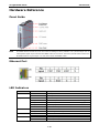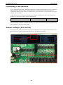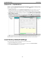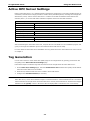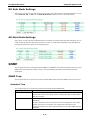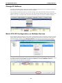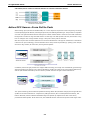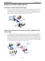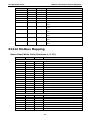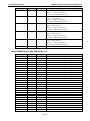
1
ioLogik E1200 Series User’s Manual Tenth Edition, April 2013 www.moxa.com/product © 2013 Moxa Inc. All rights reserved. Reproduction without permission is prohibited. ioLogik E1200 Series User’s Manual The software described in this manual is furnished under a license agreement and may be used only in accordance with the terms of that agreement. Copyright Notice Copyright ©2013 Moxa Inc. All rights reserved. Reproduction without permission is prohibited. Trademarks The MOXA logo is a registered trademark of Moxa Inc. All other trademarks or registered marks in this manual belong to their respective manufacturers. Disclaimer Information in this document is subject to change without notice and does not represent a commitment on the part of Moxa. Moxa provides this document as is, without warranty of any kind, either expressed or implied, including, but not limited to, its particular purpose. Moxa reserves the right to make improvements and/or changes to this manual, or to the products and/or the programs described in this manual, at any time. Information provided in this manual is intended to be accurate and reliable. However, Moxa assumes no responsibility for its use, or for any infringements on the rights of third parties that may result from its use. This product might include unintentional technical or typographical errors. Changes are periodically made to the information herein to correct such errors, and these changes are incorporated into new editions of the publication. Technical Support Contact Information www.moxa.com/support Moxa Americas Moxa China (Shanghai office) Toll-free: +1-888-669-2872 Toll-free: +86-800-820-5036 Tel: +1-714-528-6777 Tel: +86-21-5258-9955 Fax: +1-714-528-6778 Fax: +86-21-5258-5505 Moxa Europe Moxa Asia-Pacific Tel: +49-89-3 70 03 99-0 Tel: +886-2-8919-1230 Fax: +49-89-3 70 03 99-99 Fax: +886-2-8919-1231 Moxa India Tel: +91-80-4172-9088 Fax: +91-80-4132-1045 Table of Contents 1. Introduction ...................................................................................................................................... 1-1 Product Features ................................................................................................................................ 1-2 Inside the Box .................................................................................................................................... 1-2 Product Model Information ................................................................................................................... 1-3 Product Specifications ......................................................................................................................... 1-4 Common Specifications ................................................................................................................ 1-4 ioLogik E1210 ............................................................................................................................. 1-5 ioLogik E1211 ............................................................................................................................. 1-5 ioLogik E1212 ............................................................................................................................. 1-6 ioLogik E1213 ............................................................................................................................. 1-7 ioLogik E1214 ............................................................................................................................. 1-8 ioLogik E1240 ............................................................................................................................. 1-9 ioLogik E1241 ............................................................................................................................. 1-9 ioLogik E1242 ........................................................................................................................... 1-10 ioLogik E1260 ........................................................................................................................... 1-11 ioLogik E1262 ........................................................................................................................... 1-11 Physical Dimensions .......................................................................................................................... 1-12 Hardware Reference .......................................................................................................................... 1-13 Panel Guide .............................................................................................................................. 1-13 Ethernet Port ............................................................................................................................ 1-13 LED Indicators .......................................................................................................................... 1-13 I/O Circuit Diagram........................................................................................................................... 1-14 DI Circuit ................................................................................................................................. 1-14 Sinking DO Circuit ..................................................................................................................... 1-14 Sourcing DO Circuit ................................................................................................................... 1-15 DIO Circuit ............................................................................................................................... 1-16 Relay Circuit ............................................................................................................................. 1-17 AI Circuit .................................................................................................................................. 1-17 RTD Circuit ............................................................................................................................... 1-18 TC Circuit ................................................................................................................................. 1-18 2. Initial Setup ...................................................................................................................................... 2-1 Hardware Installation .......................................................................................................................... 2-2 Connecting the Power .................................................................................................................. 2-2 Grounding the ioLogik E1200 ........................................................................................................ 2-2 DIN Rail, Wall Mounting ............................................................................................................... 2-2 Connecting to the Network ........................................................................................................... 2-3 Jumper Settings (DIO and AI) ....................................................................................................... 2-3 DIO Mode Configuration Settings ........................................................................................... 2-4 AI Mode Configuration Settings .............................................................................................. 2-4 EXT Power Configuration Settings (ioLogik E1213 Only) ............................................................ 2-4 I/O Wiring Diagrams .................................................................................................................... 2-5 ioSearch™ Installation ......................................................................................................................... 2-7 Load Factory Default Settings ............................................................................................................... 2-7 3. Using the Web Console...................................................................................................................... 3-1 Introduction to the Web Console ........................................................................................................... 3-2 Overview ........................................................................................................................................... 3-3 Network Settings for the Web Console ................................................................................................... 3-4 General Settings ......................................................................................................................... 3-4 Ethernet Configuration ................................................................................................................. 3-4 User-Defined Modbus Addressing .......................................................................................................... 3-5 Default Modbus Address ............................................................................................................... 3-5 Active OPC Server Settings .................................................................................................................. 3-6 Tag Generation................................................................................................................................... 3-6 I/O Settings ....................................................................................................................................... 3-8 DI Channels ................................................................................................................................ 3-8 DO Channels............................................................................................................................. 3-10 AI Channels .............................................................................................................................. 3-11 AI Input Range ......................................................................................................................... 3-12 AO Channels ............................................................................................................................. 3-14 RTD Channels ........................................................................................................................... 3-15 TC Channels ............................................................................................................................. 3-17 System Management......................................................................................................................... 3-18 Accessibility IP List .................................................................................................................... 3-18 Network Connection................................................................................................................... 3-19 Firmware Update ....................................................................................................................... 3-19 Import System Configuration Settings ......................................................................................... 3-19 Export System Settings .............................................................................................................. 3-20 Peer-to-Peer Networking.................................................................................................................... 3-20 Peer-to-Peer Settings (1-50)....................................................................................................... 3-20 Sample Peer-to-Peer Configuration .............................................................................................. 3-21 Server Settings: ................................................................................................................ 3-21 Client Settings:.................................................................................................................. 3-21 DO Safe Mode Settings .............................................................................................................. 3-22 AO Safe Mode Settings............................................................................................................... 3-22 SNMP .............................................................................................................................................. 3-22 SNMP Trap ............................................................................................................................... 3-22 Standard Trap ................................................................................................................... 3-22 Private Trap ...................................................................................................................... 3-23 Using SNMP .............................................................................................................................. 3-23 SNMP Agent ...................................................................................................................... 3-23 SNMP Trap Settings............................................................................................................ 3-23 SNMP Trap Server .............................................................................................................. 3-23 SNMP Trap ........................................................................................................................ 3-24 Specific ID ........................................................................................................................ 3-24 Digital Input / Counter Trap Settings .................................................................................... 3-24 Digital Output / Pulse Output Trap Settings ........................................................................... 3-24 Analog Input Trap Settings.................................................................................................. 3-25 RTD Input Trap Settings ..................................................................................................... 3-26 TC Input Trap Settings ....................................................................................................... 3-26 Change Password ............................................................................................................................. 3-27 Load Factory Defaults ........................................................................................................................ 3-28 Save/Restart .................................................................................................................................... 3-28 4. Using ioSearch™................................................................................................................................ 4-1 Introduction to ioSearch™ ................................................................................................................... 4-2 ioSearch™ Main Screen ....................................................................................................................... 4-2 Main Screen Overview.................................................................................................................. 4-2 ioSearch™ Setup ................................................................................................................................ 4-3 System ...................................................................................................................................... 4-3 Sort ........................................................................................................................................... 4-4 Quick Links ................................................................................................................................. 4-4 Main Function ..................................................................................................................................... 4-4 Locate........................................................................................................................................ 4-5 Firmware Upgrade ....................................................................................................................... 4-5 Batch Upgrades on Multiple Devices of the Same Model ............................................................ 4-5 Unlock ....................................................................................................................................... 4-5 Import ....................................................................................................................................... 4-6 Export........................................................................................................................................ 4-6 Change IP Address ...................................................................................................................... 4-7 Batch TCP/IP Configuration on Multiple Devices............................................................................... 4-7 Restart System ........................................................................................................................... 4-8 Reset to Default .......................................................................................................................... 4-8 Mass Deployment (Import) ........................................................................................................... 4-9 Mass Deployment (Export) ........................................................................................................... 4-9 5. Active OPC Server ............................................................................................................................. 5-1 Introduction to Active OPC Server ......................................................................................................... 5-2 OLE for Process Control ................................................................................................................ 5-2 Active OPC Server—From Pull to Push ............................................................................................ 5-3 Features of Active OPC Server .............................................................................................................. 5-5 One Simple Click Creates Active Tags ............................................................................................ 5-5 Faster, More Accurate Data Collection than Traditional “Pull Technology” ............................................ 5-5 Dynamic IP Assignments for Cellular RTUs...................................................................................... 5-6 Active OPC Server Setup ..................................................................................................................... 5-6 Installing Active OPC Server ......................................................................................................... 5-6 Main Screen Overview.................................................................................................................. 5-7 Menu Bar ................................................................................................................................... 5-7 A. Modbus/TCP Default Address Mappings ............................................................................................ A-1 E1210 Modbus Mapping ....................................................................................................................... A-2 0xxxx Read/Write Coils (Functions 1, 5, 15) ............................................................................ A-2 1xxxx Read Only Coils (Function 2) ........................................................................................ A-4 3xxxx Read Only Registers (Function 4) .................................................................................. A-4 E1211 Modbus Mapping ....................................................................................................................... A-5 0xxxx Read/Write Coils (Functions 1, 5, 15) ............................................................................ A-5 1xxxx Read Only Coils (Function 2) ........................................................................................ A-6 E1212 Modbus Mapping ....................................................................................................................... A-7 0xxxx Read/Write Coils (Functions 1, 5, 15) ............................................................................ A-7 1xxxx Read Only Coils (Function 2) ...................................................................................... A-10 3xxxx Read Only Registers (Function 4) ................................................................................ A-11 4xxxx Read/Write Registers (Functions 3, 6, 16).................................................................... A-11 E1213 Modbus Mapping ..................................................................................................................... A-11 E1214 E1240 E1241 E1242 E1260 E1262 0xxxx Read/Write Coils (Functions 1, 5, 15) .......................................................................... A-11 1xxxx Read Only Coils (Function 2) ...................................................................................... A-13 3xxxx Read Only Registers (Function 4) ................................................................................ A-14 4xxxx Read/Write Registers (Functions 3, 6, 16).................................................................... A-14 Modbus Mapping ..................................................................................................................... A-15 0xxxx Read/Write Coils (Functions 1, 5, 15) .......................................................................... A-15 1xxxx Read Only Coils (Function 2) ...................................................................................... A-16 3xxxx Read Only Registers (Function 4) ................................................................................ A-17 4xxxx Read/Write Registers (Functions 3, 6, 16).................................................................... A-17 Modbus Mapping ..................................................................................................................... A-17 0xxxx Read/Write Coils (Functions 1, 5, 15) .......................................................................... A-17 3xxxx Read Only Registers (Function 4) ................................................................................ A-17 3xxxx Read Only Registers (Function 4) ................................................................................ A-19 Modbus Mapping ..................................................................................................................... A-19 0xxxx Read/Write Coils (Functions 1, 5, 15) .......................................................................... A-19 3xxxx Read Only Registers (Function 4) ................................................................................ A-20 4xxxx Read/Write Registers (Functions 3, 6, 16).................................................................... A-20 Modbus Mapping ..................................................................................................................... A-20 0xxxx Read/Write Coils (Functions 1, 5, 15) .......................................................................... A-20 1xxxx Read Only Coils (Function 2) ...................................................................................... A-21 3xxxx Read Only Registers (Function 4) ................................................................................ A-22 4xxxx Read/Write Registers (Functions 3, 6, 16).................................................................... A-23 Modbus Mapping ..................................................................................................................... A-23 0xxxx Read/Write Coils (Functions 1, 5, 15) .......................................................................... A-23 3xxxx Read Only Registers (Function 4) ................................................................................ A-23 Modbus Mapping ..................................................................................................................... A-24 3xxxx Read Only Registers (Function 4) ................................................................................ A-24 B. Network Port Numbers...................................................................................................................... B-1 C. Factory Default Settings .................................................................................................................... C-1 D. Pinouts .............................................................................................................................................. D-1 E. FCC Interference Statement .............................................................................................................. E-1 F. European Community (CE) ................................................................................................................ F-1 1 1. Introduction The ioLogik E1200 industrial Ethernet remote I/O has two embedded Ethernet switch ports that allow information to flow to another local Ethernet device or connect to the next ioLogik in the daisy-chain. Applications such as factory automation, security and surveillance systems, and tunnel monitoring, can make use of daisy-chained Ethernet for building multi-drop I/O networks over standard Ethernet cables and familiar fieldbus protocols. The daisy-chain function on the ioLogik E1200 Ethernet remote I/O not only increases the connections between machines and panels, but also lowers the cost of buying separate Ethernet switches, and at the same time reduces labor fees and cabling by a large percentage. For example, if a production facility contains 700 stations (20 points per station), the wiring cost reduction can reach 15% of the total implementation cost. The following topics are covered in this chapter: Product Features Inside the Box Product Model Information Product Specifications Common Specifications ioLogik E1210 ioLogik E1211 ioLogik E1212 ioLogik E1213 ioLogik E1214 ioLogik E1240 ioLogik E1241 ioLogik E1242 ioLogik E1260 ioLogik E1262 Physical Dimensions Hardware Reference Panel Guide Ethernet Port LED Indicators I/O Circuit Diagram DI Circuit Sinking DO Circuit Sourcing DO Circuit DIO Circuit Relay Circuit AI Circuit RTD Circuit TC Circuit ioLogik E1200 Series Introduction Product Features • Active communication with patented Active OPC Server • 2-port Ethernet switch for daisy-chain topologies • Easy mass deployment and configuration with ioSearch™utility • User-friendly configuration via web browser • Save time and wiring costs with peer-to-peer communication • User-defined Modbus/TCP addressing • Simplify I/O management with MXIO library on either Windows or Linux platform • Wide operating temperature: -40 to 75°C (-40 to 167°F) • Supports SNMPv1/v2c • UL/cUL Class I Division 2, ATEX Zone 2 certification Inside the Box The ioLogik E1200 is shipped with the following items: NOTE • ioLogik E1200 remote Ethernet I/O server • Document and software CD • Quick installation guide Notify your sales representative if any of the above items are missing or damaged. 1-2 ioLogik E1200 Series Introduction Product Model Information Model Description ioLogik E1210 Remote Ethernet I/O with 2-port Ethernet switch and 16 DIs ioLogik E1211 Remote Ethernet I/O with 2-port Ethernet switch and 16 DOs ioLogik E1212 Remote Ethernet I/O with 2-port Ethernet switch, 8 DIs, and 8 DIOs ioLogik E1213 Remote Ethernet I/O with 2-port Ethernet switch, 8 DIs, 4 DOs, and 8 DIOs (source type) ioLogik E1214 Remote Ethernet I/O with 2-port Ethernet switch, 6 DIs, and 6 relays ioLogik E1240 Remote Ethernet I/O with 2-port Ethernet switch and 8 AIs ioLogik E1241 Remote Ethernet I/O with 2-port Ethernet switch and 4 AOs ioLogik E1242 Remote Ethernet I/O with 2-port Ethernet switch and 4 AIs, 4DIs, and 4DIOs ioLogik E1260 Remote Ethernet I/O with 2-port Ethernet switch and 6 RTDs ioLogik E1262 Remote Ethernet I/O with 2-port Ethernet switch and 8 TCs ioLogik E1210-T Ethernet remote I/O with 2-port Ethernet switch and 16 DIs, -40 to 75°C operating ioLogik E1211-T Ethernet remote I/O with 2-port Ethernet switch and 16 DOs, -40 to 75°C operating temperature temperature ioLogik E1212-T Ethernet remote I/O with 2-port Ethernet switch, 8 DIs, and 8 DIOs, -40 to 75°C operating temperature ioLogik E1213-T Remote Ethernet I/O with 2 Port Ethernet switch, 8 DIs, 4 DOs, and 8 DIOs (source type), -40 to 75°C operating temperature ioLogik E1214-T Ethernet remote I/O with 2-port Ethernet switch, 6 DIs, and 6 Relays, -40 to 75°C ioLogik E1240-T Ethernet remote I/O with 2-port Ethernet switch and 8 AIs, -40 to 75°C operating operating temperature temperature ioLogik E1241-T Ethernet remote I/O with 2-port Ethernet switch and 4 AOs , -40 to 75°C operating ioLogik E1242-T Ethernet remote I/O with 2-port Ethernet switch, 4 AIs, 4 DIs, and 4 DIOs, -40 to 75°C ioLogik E1260-T Ethernet remote I/O with 2-port Ethernet switch and 6 RTDs, -40 to 75°C operating temperature operating temperature temperature ioLogik E1262-T Ethernet remote I/O with 2-port Ethernet switch and 8 TCs, -40 to 75°C operating temperature 1-3 ioLogik E1200 Series Introduction Product Specifications Common Specifications LAN Ethernet: 2 x 10/100 Mbps switch ports, RJ45 Protection: 1.5 kV magnetic isolation Protocols: Modbus/TCP, TCP/IP, UDP, DHCP, BOOTP, HTTP Power Requirements Power Input: 24 VDC nominal, 12 to 36 VDC Physical Characteristics Wiring: I/O cable max. 14 AWG Dimensions: 27.8 x 124 x 84 mm (1.09 x 4.88 x 3.31 in) Weight: under 200 g Mounting: DIN rail or wall Environmental Limits Operating Temperature: Standard Models: -10 to 60°C (14 to 140°F) Wide Temp. Models: -40 to 75°C (-40 to 167°F) Storage Temperature: -40 to 85°C (-40 to 185°F) Ambient Relative Humidity: 5 to 95% (non-condensing) Altitude: Up to 2000 m Note: Please contact Moxa if you require products guaranteed to function properly at higher altitudes. Standards and Certifications Safety: UL 508 EMI: EN 55022; EN 61000-3-2; EN 61000-3-3; FCC Part 15, Subpart B, Class A EMS: EN 55024, EN 61000-4-2, EN 61000-4-3, EN 61000-4-4, EN 61000-4-5, EN 61000-4-6, EN 61000-4-8, EN 61000-4-11 Shock: IEC 60068-2-27 Freefall: IEC 60068-2-32 Vibration: IEC 60068-2-6 Green Product: RoHS, CRoHS, WEEE Hazardous Location: UL/cUL Class I Division 2, ATEX Zone 2 (ioLogik E1214 pending) Note: Please check Moxa's website for the most up-to-date certification status. Warranty Warranty Period: 5 years (excluding ioLogik E1214) Details: See www.moxa.com/warranty Note: Because of the limited lifetime of power relays, products that use this component are covered by a 2-year warranty. 1-4 ioLogik E1200 Series Introduction ioLogik E1210 Inputs and Outputs Digital Inputs: 16 channels Isolation: 3K VDC or 2K Vrms Digital Input Sensor Type: Wet Contact (NPN or PNP), Dry Contact I/O Mode: DI or Event Counter Dry Contact: • On: short to GND • Off: open Wet Contact: NPN (DI to GND): • On: 0 to 3 VDC • Off: 10 to 30 VDC PNP (DI to GND): • Off: 0 to 3 VDC • On: 10 to 30 VDC Common Type: 8 points per COM Counter Frequency: 250 Hz, power off storage Digital Filtering Time Interval: Software selectable Power Requirements Power Consumption: 110 mA @ 24 VDC MTBF (mean time between failures) Time: 671,345 hrs Database: Telcordia (Bellcore) ioLogik E1211 Inputs and Outputs Digital Outputs: 16 channels Isolation: 3K VDC or 2K Vrms Digital Output Type: Sink I/O Mode: DO or Pulse Output Pulse Output Frequency: 500 Hz Over-voltage Protection: 45 VDC Over-current Protection: 2.6 A (4 channels @ 650 mA) Over-temperature Shutdown: 175°C (typical), 150°C (min.) Current Rating: 200 mA per channel Power Requirements Power Consumption: 208 mA @ 24 VDC MTBF (mean time between failures) Time: 923,027 hrs Database: Telcordia (Bellcore) 1-5 ioLogik E1200 Series Introduction ioLogik E1212 Inputs and Outputs Digital Inputs: 8 channels Configurable DIOs: 8 channels Isolation: 3K VDC or 2K Vrms Digital Input Sensor Type: Wet Contact (NPN or PNP), Dry Contact I/O Mode: DI or Event Counter Dry Contact: • On: short to GND • Off: open Wet Contact: NPN (DI to GND): • On: 0 to 3 VDC • Off: 10 to 30 VDC PNP (DI to GND): • Off: 0 to 3 VDC • On: 10 to 30 VDC Common Type: 8 points per COM Counter Frequency: 250 Hz, power off storage Digital Filtering Time Interval: Software selectable Digital Output Type: Sink I/O Mode: DO or Pulse Output Pulse Output Frequency: 500 Hz Over-voltage Protection: 45 VDC Over-current Protection: 2.6 A (4 channels @ 650 mA) Over-temperature Shutdown: 175°C (typical), 150°C (min.) Current Rating: 200 mA per channel Power Requirements Power Consumption: 155 mA @ 24 VDC MTBF (mean time between failures) Time: 561,930 hrs Database: Telcordia (Bellcore) 1-6 ioLogik E1200 Series Introduction ioLogik E1213 Inputs and Outputs Digital Inputs: 8 channels Digital Outputs: 4 channels Digital Input/Output (configurable by jumper): 4 channels Isolation: 3K VDC or 2K Vrms Digital Input Sensor Type: NPN, PNP, and dry contact I/O Mode: DI or event counter Dry Contact: • Logic 0: short to GND • Logic 1: open Wet Contact: • Logic 0: 0 to 3 VDC • Logic 1: 10 to 30 VDC (DI COM to DI) Common Type: 12 points per COM Counter/Frequency: 250 Hz, power off storage Digital Output I/O Mode: DO or Pulse Output I/O Type: Source Current: 500 mA per channel Voltage: 15 to 30 VDC (12 or 9 VDC configurable by jumper on the 4 DO channels) Pulse Wave Width/Frequency: 1 ms/500 Hz Over-Voltage Protection: 45 VDC Over-Current Limit: 1.5 A per channel @ 25°C Over-Temperature Shutdown: 175°C (typical), 150°C (min.) Output Current Rating: 0.5A per channel Power Requirements Power Input: 24 VDC nominal, 12 to 36 VDC Power Consumption: 130 mA typical @ 24 VDC 1-7 ioLogik E1200 Series Introduction ioLogik E1214 Inputs and Outputs Digital Inputs: 6 channels Relay Outputs: 6 channels Isolation: 3K VDC or 2K Vrms Digital Input Sensor Type: Wet Contact (NPN or PNP), Dry Contact I/O Mode: DI or Event Counter Dry Contact: • On: short to GND • Off: open Wet Contact: NPN (DI to GND): • On: 0 to 3 VDC • Off: 10 to 30 VDC PNP (DI to GND): • Off: 0 to 3 VDC • On: 10 to 30 VDC Common Type: 6 points per COM Counter Frequency: 250 Hz, power off storage Digital Filtering Time Interval: Software selectable Relay Output Type: Form A (N.O.) power relay Contact Current Rating: • Resistive Load: 5 A @ 30 VDC, 250 VAC, 110 VAC Breakdown Voltage: 500 VAC Relay On/Off Time: 1500 ms (max.) Initial Insulation Resistance: 1000 M ohms (min.) @ 500 VDC Mechanical Endurance: 5,000,000 operations Electrical Endurance: 100,000 operations @ 5 A resistive load Contact Resistance: 100 m ohms (max.) Pulse Output: 0.3 Hz at rated load Note: Ambient humidity must be non-condensing and remain between 5 and 95%. The relays of the ioLogik E1214 may malfunction when operating in high condensation environments below 0° Celsius. Power Requirements Power Consumption: 188 mA @ 24 VDC MTBF (mean time between failures) Time: 808,744 hrs Database: Telcordia (Bellcore) 1-8 ioLogik E1200 Series Introduction ioLogik E1240 Inputs and Outputs Analog Inputs: 8 channels Isolation: 3K VDC or 2K Vrms Analog Input Type: Differential input Resolution: 16 bits I/O Mode: Voltage / Current Input Range: 0 to 10 VDC, 0 to 20 mA, 4 to 20 mA Accuracy: ±0.1% FSR @ 25°C ±0.3% FSR @ -10 and 60°C ±0.5% FSR @ -40 and 75°C Sampling Rate: • All channels: 12 samples/sec • Per channel: 1.5 samples/sec • Only one channel enabled: 12 samples/sec Input Impedance: 10M ohms (min.) Built-in Resistor for Current Input: 120 ohms Power Requirements Power Consumption: 121 mA @ 24 VDC MTBF (mean time between failures) Time: 474,053 hrs Database: Telcordia (Bellcore) ioLogik E1241 Inputs and Outputs Analog Outputs: 4 channels Isolation: 3K VDC or 2K Vrms Analog Output Resolution: 12 bits Output Range: 0 to 10 VDC, 4 to 20 mA Voltage Output: 10 mA (max.) Accuracy: ±0.1% FSR @ 25°C ±0.3% FSR @ -40 and 75°C Load Resistor: • Internal resistor: 400 ohms Note: 24 V of external power required when loading greater than 1000 ohms. Power Requirements Power Consumption: 194 mA @ 24 VDC MTBF (mean time between failures) Time: 888,656 hrs Database: Telcordia (Bellcore) 1-9 ioLogik E1200 Series Introduction ioLogik E1242 Inputs and Outputs Analog Inputs: 4 channels Digital Inputs: 4 channels Configurable DIOs: 4 channels Isolation: 3K VDC or 2K Vrms Analog Input Type: Differential input Resolution: 16 bits I/O Mode: Voltage / Current Input Range: 0 to 10 VDC, 0 to 20 mA, 4 to 20 mA Accuracy: ±0.1% FSR @ 25°C ±0.3% FSR @ -10 and 60°C ±0.5% FSR @ -40 and 75°C Sampling Rate: • All channels: 12 samples/sec • Per channel: 3 samples/sec • Only one channel enabled: 12 samples/sec Input Impedance: 10M ohms (min.) Built-in Resistor for Current Input: 120 ohms Digital Input Sensor Type: Wet Contact (NPN or PNP), Dry Contact I/O Mode: DI or Event Counter Dry Contact: • On: short to GND • Off: open Wet Contact: NPN (DI to GND): • On: 0 to 3 VDC • Off: 10 to 30 VDC PNP (DI to GND): • Off: 0 to 3 VDC • On: 10 to 30 VDC Common Type: 4 points per COM Counter Frequency: 250 Hz, power off storage Digital Filtering Time Interval: Software selectable Digital Output Type: Sink I/O Mode: DO or Pulse Output Pulse Output Frequency: 500 Hz Over-voltage Protection: 45 VDC Over-current Protection: 2.6 A (4 channels @ 650 mA) Over-temperature Shutdown: 175°C (typical), 150°C (min.) Current Rating: 200 mA per channel Power Requirements Power Consumption: 139 mA @ 24 VDC MTBF (mean time between failures) Time: 502,210 hrs Database: Telcordia (Bellcore) 1-10 ioLogik E1200 Series Introduction ioLogik E1260 Inputs and Outputs RTD Inputs: 6 channels Isolation: 3K VDC or 2K Vrms RTD Inputs Input Type: • PT50, PT100, PT200, PT500 (-200 to 850°C) • PT1000 (-200 to 350°C) • Resistance of 310, 620, 1250, and 2200 ohms Sampling Rate: • All channels: 12 samples/sec • Per channel: 2 samples/sec • Only one channel enabled: 12 samples/sec Resolution: 0.1°C or 0.1 ohm Accuracy: ±0.1% FSR @ 25°C ±0.3% FSR @ -40 and 75°C Input Impedance: 625K ohms Power Requirements Power Consumption: 110 mA @ 24 VDC MTBF (mean time between failures) Time: 660,260 hrs Database: Telcordia (Bellcore) ioLogik E1262 Inputs and Outputs Thermocouple Inputs: 8 channels Isolation: 3K VDC or 2K Vrms Thermocouple Input Sensor Type: J (0 to 750°C), K (-200 to 1250°C), T (-200 to 350°C), E (-200 to 900°C), R (-50 to 1600°C), S (-50 to 1760°C), B (600 to 1700°C), N (-200 to 1300°C) Millivolt Type: • Mode: ±78.126 mV, ±39.062 mV, ±19.532 mV • Fault and over-voltage protection: -35 to +35 VDC (power off); -25 to +30 VDC (power on) Sampling Rate: • All channels: 12 samples/sec • Per channel: 1.5 samples/sec • Only one channel enabled: 12 samples/sec Resolution: 16 bits Accuracy: ±0.1% FSR @ 25°C ±0.3% FSR @ -40 and 75°C Input Impedance: 10M ohms Power Requirements Power Consumption: 118 mA @ 24 VDC MTBF (mean time between failures) Time: 631,418 hrs Database: Telcordia (Bellcore) 1-11 ioLogik E1200 Series Introduction Physical Dimensions 1-12 ioLogik E1200 Series Introduction Hardware Reference Panel Guide NOTE The RESET button restarts the server and resets all settings to factory defaults. Use a pointed object such as a straightened paper clip to hold down the RESET button for 5 seconds. The factory defaults will be loaded once the READY LED turns green again. You may then release the RESET button. Ethernet Port LED Indicators LED State Description Power Amber System power is ON OFF System power is OFF Green System is ready Flashing Flashes every 1 second when the “Locate” function is triggered Flashing Flashes every 0.5 second when the firmware is being upgraded Ready Port 1 Port 2 EXT Flashing ON/OFF cycle period of 0.5 second represents “Safe Mode” OFF System is not ready Green Ethernet connection enabled Flashing Transmitting or receiving data Green Ethernet connection enabled Flashing Transmitting or receiving data Green EXT field power input is connected Off EXT field power input is disconnected 1-13 ioLogik E1200 Series Introduction I/O Circuit Diagram DI Circuit Sinking DO Circuit 1-14 ioLogik E1200 Series Introduction Sourcing DO Circuit 1-15 ioLogik E1200 Series Introduction DIO Circuit 1-16 ioLogik E1200 Series Introduction Relay Circuit AI Circuit 1-17 ioLogik E1200 Series Introduction RTD Circuit TC Circuit 1-18 2 2. This chapter describes how to install the ioLogik E1200. The following topics are covered in this chapter: Hardware Installation Connecting the Power Grounding the ioLogik E1200 DIN Rail, Wall Mounting Connecting to the Network Jumper Settings (DIO and AI) I/O Wiring Diagrams ioSearch™ Installation Load Factory Default Settings Initial Setup ioLogik E1200 Series Initial Setup Hardware Installation Connecting the Power Connect the 12 to 36 VDC power line to the ioLogik E1200’s terminal block on the top panel. If power is properly supplied, the Power LED will glow a solid amber color. ATTENTION Determine the maximum possible current for each power wire and common wire. Observe all electrical codes dictating the maximum current allowable for each wire size. If the current exceeds the maximum rating, the wiring may overheat, causing serious damage to your equipment. For safety reasons, we recommend an average cable size of 22 AWG. However, depending on the current load, you may want to adjust your cable size (the maximum wire size for power connectors is 2 mm). Grounding the ioLogik E1200 The ioLogik E1200 is equipped with a grounding point on the terminal block located on the top panel. Connect the ground pin ( ) if earth ground is available. DIN Rail, Wall Mounting There are two sliders on the back of the unit for DIN rail and wall mounting. Mounting on a DIN rail: Pull out the bottom slider, latch the unit onto the DIN rail, and push the slider back in. Mounting on the wall: Pull out both the top and bottom sliders and align the screws accordingly. 2-2 ioLogik E1200 Series Initial Setup Connecting to the Network The ioLogik E1200 has two built-in RJ45 Ethernet ports for connecting a standard direct or cross-over Ethernet cable to either the host PC or another ioLogik E1200 device. For initial setup of the ioLogik E1200, it is recommended that the ioLogik E1200 be configured using a direct connection to a host computer rather than remotely over the network. Configure the host PC’s IP address to 192.168.127.xxx (where xxx ranges from 001 to 253). When using Windows, you will need to configure from the Control Panel. ioLogik E1200 Default IP Address Default Netmask Default Gateway 192.168.127.254 255.255.255.0 None Use the web console or ioSearch™ configuration utility to connect to the ioLogik E1200. Once the ioLogik E1200 has been detected, modify the settings as needed for your network environment, and then restart the server. Refer to Chapters 3 and 4 for further details. Jumper Settings (DIO and AI) The ioLogik E1212, E1240, and E1242 models require configuration for the jumpers located inside the cover. Remove the screw on the back panel and open the cover to configure the jumpers. 2-3 ioLogik E1200 Series Initial Setup DIO Mode Configuration Settings DIO mode configuration settings are shown below: The default setting is DO Mode. AI Mode Configuration Settings Analog mode configuration settings are shown below: The default setting is Voltage Mode. EXT Power Configuration Settings (ioLogik E1213 Only) The ioLogik E1213 digital outputs have 3 possible external (EXT) power configurations. Only one field power configuration can be selected at a time (JP10 / 12V JP5 / 9V JP11) and the jumper must be inserted vertically, not horizontally. EXT power configuration settings are shown below: The default setting is Field Power JP10. NOTE The ioLogik E1213 has 4 pure DO channels and 4 hybrid DIO channels. For the 4 pure DO channels, you can use the jumpers to select the power configuration output (i.e., field power, 12 V, 9 V). But for the 4 hybrid DIO channels, you cannot use the jumpers to select the power configuration output. Instead, you can only use the jumpers to set the DIO channels to either DI mode or DO mode. 2-4 ioLogik E1200 Series Initial Setup I/O Wiring Diagrams A Dry Contact is a contact that does not provide voltage. A Wet Contact is a contact that will provide voltage when closed. ATTENTION Remove the screw on the back panel and open the cover to configure the jumpers. 2-5 ioLogik E1200 Series NOTE Initial Setup It is recommended to use a contact protection circuit for relay output. A varistor can serve as a contact protection circuit, where the parallel circuit connects to the Load. Load 2-6 ioLogik E1200 Series Initial Setup ioSearch™ Installation ioSearch™ is a search utility that helps the user locate ioLogik E1200 devices on the local network. Find the ioSearch™ utility in the Document and Software CD under Software ioSearch, or download the latest version from Moxa’s website. 1. Installing from the CD: Insert the Document and Software CD into the host computer. In the root directory of the CD, locate and run SETUP.EXE. The installation program will guide you through the installation process and install the ioSearch™ utility. You can also install the MXIO DLL library separately. 2. Open ioSearch: After installation is finished, run ioSearch™ from Start Program Files MOXA IO Server Utility ioSearch. 3. Search the network for the server: On the menu bar, select System Auto Scan Active Ethernet I/O Server. A dialog window will pop up. Click Start Search to begin searching for the ioLogik E1200. If multiple ioLogik E1200 units are installed on the same network, remember that each unit has the same default IP address. You will need to assign a different IP address to each unit to avoid IP conflicts. Load Factory Default Settings There are three ways to restore the ioLogik E1200 to factory default settings. 1. Hold down the RESET button for 5 seconds 2. Right-click on the specific ioLogik device in the ioSearch™ utility and select Reset to Default 3. Select Load Factory Default from the web console 2-7 3 3. Using the Web Console The ioLogik E1200’s main configuration and management utility is the built-in web console, which can be used to configure a wide range of options. The following topics are covered in this chapter: Introduction to the Web Console Overview Network Settings for the Web Console General Settings Ethernet Configuration User-Defined Modbus Addressing Default Modbus Address Active OPC Server Settings Tag Generation I/O Settings DI Channels DO Channels AI Channels AI Input Range AO Channels RTD Channels TC Channels System Management Accessibility IP List Network Connection Firmware Update Import System Configuration Settings Export System Settings Peer-to-Peer Networking Peer-to-Peer Settings (1-50) Sample Peer-to-Peer Configuration DO Safe Mode Settings AO Safe Mode Settings SNMP SNMP Trap Using SNMP Change Password Load Factory Defaults Save/Restart ioLogik E1200 Series Using the Web Console Introduction to the Web Console The ioLogik E1200 web console is a browser-based configuration utility. When the ioLogik E1200 is connected to your network, you may enter the server’s IP address in your web browser to access the web console. The left panel is the navigation panel and contains an expandable menu tree for navigating among the various settings and categories. When you click on a menu item in the navigation panel, the main window will display the corresponding options for that item. Configuration changes can then be made in the main window. For example, if you click on Network Settings in the navigation panel, the main window will show a page of basic settings that you can configure. You must click on the Submit button after making configuration changes. The Submit button will be located at the bottom of every page that has configurable settings. If you navigate to another page without clicking the Submit button, your changes will not be retained. Submitted changes will not take effect until they are saved and the ioLogik E1200 is restarted! You may save and restart the server in one step by clicking on the Save/Restart button after you submit a change. If you need to make several changes before restarting, you may save your changes without restarting by selecting Save/Restart in the navigation panel. If you restart the ioLogik E1200 without saving your configuration, the ioLogik E1200 will discard all submitted changes. 3-2 ioLogik E1200 Series Using the Web Console Overview The Overview page contains basic information about the ioLogik E1200, including the model name, serial number, firmware version, MAC address, and current IP address. Most importantly, you can see the current I/O status by pressing the F5 key on the computer keyboard to refresh the page. 3-3 ioLogik E1200 Series Using the Web Console Network Settings for the Web Console General Settings On the General Settings page, you can assign a server name and location to assist you in differentiating between different ioLogik E1200 units. You may also configure the Modbus/TCP timeout interval or enable the Communication Watchdog function. Enable Server Socket Idle Connection Timeout Interval automatically disconnects the Modbus/TCP connection from the server after a specified time period to free up the port for the next connection. Enable Communication Watchdog activates Safe Mode when a specified period of time has passed and there is a loss of Modbus/TCP network connectivity. Safe Mode is specially designed for products with output channels to output a suitable value (see Chapter 3: AO Safe Mode Setting) or status (see Chapter 3: DO Safe Mode Setting) when the ioLogik E1200 cannot be controlled by a remote PC (such as in the event of a network failure). By default, the watchdog is disabled. Users can configure how each output channel responds on the I/O Settings page. To enable the Communication Watchdog function, select the Enable Communication Watchdog checkbox, set the timeout value, and then restart the server. When the watchdog is enabled, the ioLogik E1200 will enter Safe Mode after there is a disruption in communication that exceeds the specified time limit. Enable I/O Locate enables remote toggling of the Ready LED from off to flashing to enable remote control of LEDs for easier location of devices when troubleshooting. Ethernet Configuration On the Ethernet Configuration page, you can set up a static or dynamic IP address for the ioLogik E1200, and configure the subnet mask and gateway address. 3-4 ioLogik E1200 Series Using the Web Console User-Defined Modbus Addressing The input and output address can be configured in a different format on a specific settings page. Check the Enable User-defined Modbus Addressing box, select the Modbus function, and then configure the start address of each item. Default Modbus Address You can view the default Modbus address for all I/O devices on the Default Modbus Address settings page. However, only the starting address will be displayed for each item with multiple reference addresses. For example, if the reference addresses for DI Value start from 10001 and the second DI channel’s reference address is 10002, only the first DI channel’s Modbus address of 10001 will be displayed. See the diagram below. ATTENTION Disable the user-defined Modbus addressing function if using the MXIO (.NET) library or Active OPC Server to control or monitor the ioLogik E1200’s I/O status. 3-5 ioLogik E1200 Series Using the Web Console Active OPC Server Settings Moxa’s Active OPC Server™ is a software package operated as an OPC driver of an HMI or SCADA system. It seamlessly connects Moxa’s ioLogik products to a wide variety of SCADA systems, including the most popular: Wonderware, Citect, and iFix. Active OPC Server™ conforms to the OPC Foundation’s latest data access standard, DA 3.0, to connect with other standards-compliant devices and host OPC machines. Hardware Requirements CPU Intel Pentium 4 and above RAM 512 MB (1024 MB recommended) Network Interface 10/100 MB Ethernet Software Requirements Operating System Microsoft Windows 2000, XP or later Editor (not required) Microsoft Office 2003 (Access 2003) or later OPC Server Specifications OPC Data Access 1.0a, 2.0, 2.05a, 3.0 Max. No. of Tags 5000 (V1.12 or later) Active OPC Server can be downloaded from the Moxa website support page at www.moxa.com/support/. After downloading the Active OPC Server file, unzip the file and run Install.exe. The installation program will guide you through the installation process and install the Active OPC Server Utility. For more details on Active OPC Server installation and use, please refer to the Active OPC Server user’s manual or Chapter 5. Tag Generation Use the web console to create Active OPC (AOPC) tags for the ioLogik E1200 by opening your browser and navigating to the Active OPC Server Settings page. Follow these steps to create the tags and send them from the ioLogik E1200 to Active OPC Server: 1. On the AOPC & I/O Settings page, select the Enable Active OPC checkbox and specify the IP address where the Active OPC Server is installed. 2. Select the I/O channels that need to be created in Active OPC Server. 3. Configure the Heartbeat Interval, if necessary. NOTE The Heartbeat Interval can be used to determine the connection status between the ioLogik E1200 and Active OPC Server, and to ensure that the ioLogik is connected and alive. If the heartbeat interval is set and the network between the ioLogik E1200 and Active OPC Server is down, Active OPC Server will detect the stopped heartbeat and the Quality column in the Active OPC will display BAD to indicate the loss of connectivity. 3-6 ioLogik E1200 Series Using the Web Console 4. Click the Submit button and then the Save/Restart button on the next page. 5. On the Create AOPC Tag page, click on the Create Tags button to “push” tag configurations to the Active OPC Server utility. 6. Launch the Active OPC Server utility and the tags will be automatically created. Remember to save the configuration of the Active OPC Server when exiting the program. 3-7 ioLogik E1200 Series Using the Web Console I/O Settings DI Channels The status of each DI (digital input) channel appears on the DI Channel Settings page. You can also configure each channel’s digital input mode and parameters by clicking on the channel. DI channels can operate in DI mode or Event Counter mode. Activate Event Counter mode by selecting the Counter Start field and configure the Counter Trigger by selecting Lo to Hi, Hi to Lo, or Both from the dropdown menu. When the Counter Start field is not selected, you can still activate the counter by using Modbus commands. NOTE Confirm that the Counter Filter is not set to 0; otherwise, the counter will never be activated. Power On Settings: You may configure DI channels in Event Counter mode whether or not counting begins when powering up. Safe Status Settings: For DI channels in Event Counter mode, you can configure whether or not counting starts or continues when Safe Status has been activated. When the network connection is lost, as specified in the Host Connection Watchdog, the ioLogik E1200 will start or stop the counter according to the channel’s Safe Status settings. 3-8 ioLogik E1200 Series NOTE Using the Web Console The Host Connection Watchdog is disabled by default, and must be enabled for Safe Status settings to take effect. Save Status On Power Failure: The ioLogik E1200 will automatically save the counter value when there is a power failure if this function selected. Reset Counter: Select this function to reset the counter. The DI channel’s Alias Name and logic definition can also be configured on this page. You can apply the alias name to all channels by selecting the Apply to all DI channels checkbox. DI Channel Specification: 3-9 ioLogik E1200 Series Using the Web Console DO Channels On the I/O Setting: DO (Digital Output) Channels page, you can configure each DO channel by clicking on the channel. DO channels can operate in DO mode when the status is either ON or OFF. If you select Pulse Output mode, you can specify the ON Width and OFF Width to generate a square wave. Pulse Width unit = 1 ms, range = 1–65535 When configuring individual channels, if the Power On Setting is selected, the Pulse Output will start as soon as the ioLogik E1200 is powered on. If the Safe Status Setting is selected, the Pulse Output will start only when the E1200 has entered Safe Status mode. In contrast, when neither of these settings is selected and the Pulse Start field is selected, the ioLogik E1200 will automatically stop the Pulse Output when the ioLogik E1200 is either powered on or in Safe Status mode. NOTE Safe Status is controlled by the Communication Watchdog under General Settings, which is disabled by default. If the Communication Watchdog is disabled, the ioLogik E1200 will never enter Safe Mode and your Safe Status settings will have no effect. 3-10 ioLogik E1200 Series Using the Web Console The DO channel’s Alias Name and logic definition can also be configured on this page. You can apply the alias name to all channels by click on the Apply to all DO channels box. AI Channels The current status of each AI (analog input) channel can be viewed on the AI Channel Settings page. 3-11 ioLogik E1200 Series Using the Web Console Click on a specific AI channel to enable or disable it by selecting the Enable AI Channel field. There are two modes available for the AI channels: 1. Voltage Mode (See the Jumper Settings (DIO and AI) in Chapter 2 for more details) 2. Current Mode (See the Jumper Settings (DIO and AI) in Chapter 2 for more details) Auto Scaling and Slope-intercept functions of the AI value can be defined on this page. AI Input Range Set the AI input ranges for each mode, as follows: 1. Voltage Mode (V) (See Jumper Settings (DIO and AI) in Chapter 2 for more details) There is only one default analog Voltage input range: [0-10V] 2. Current Mode (mA) (See Jumper Settings (DIO and AI) in Chapter 2 for more details) There are three modes in the analog Current input range: [4-20 mA], [0-20 mA], [4-20 mA (Burn Out)] NOTE Only input ranges [0-10 V] and [4-20 mA] support peer-to-peer networking. 3-12 ioLogik E1200 Series Using the Web Console AI Input: Current Mode Burn Out mode indicates when the Current AI has burned out. For example, the 4–20 mA Burn Out mode is defined in the following diagram: Users can define Burn Out (BO) values (default = 2 mA) for selected ranges. When input values are in the Burn Out range, raw data will register as 0000h to indicate that the analog input has burned out. The definition of raw data is as follows: Burnout Value (BO) 0.0 < BO < 4.0 User defined (default 2 mA) Burnout State 0 ≤ AI < BO mA S/W output 0000h Under Range BO ≤ AI < 4 mA S/W output raw data Normal Range 4 ≤AI ≤ 20.00 mA S/W output raw data until FFFEh Over Range XX > 20.00 mA S/W output FFFFh ATTENTION When configuring the jumpers to select voltage or current measurement for the AI channels, open the cover by first removing the screw on the back panel. For details on jumper settings, see the Jumper Settings (DIO and AI) section in Chapter 2. 3-13 ioLogik E1200 Series Using the Web Console Selecting Enable Point-Slope formula on the Auto Scaling Settings page will linearly convert the actual current or voltage value into other user-defined units, such as percentage or ppm (parts per million). NOTE The scaled value’s Modbus address differs from the original value. The slope-intercept function is used to compensate when the measurement requires a slight adjustment. The AI channel’s Alias Name can also be configured on this page. AO Channels The current status of each AO (analog output) channel can be viewed on the AO Channel Settings page: Click on a specific channel to access the AO channel settings, and then select the Enable AO Channel box. The Auto Scaling function of the AO value can be defined on the same page. There are two modes for the AO channels, Voltage Mode (V) and Current Mode (mA). 3-14 ioLogik E1200 Series Using the Web Console Enabling the Point-Slope Formula function on the Auto Scaling Settings page will linearly convert the actual current or voltage value into other user-defined units, such as percentage or ppm (parts per million). NOTE The scaled value’s Modbus address differs from the original value. The AO channel’s Alias Name can also be configured on this page. RTD Channels The current status of each RTD (Resistance Temperature Detector) channel can be viewed on the RTD Channel page. Click on a specific channel to access the RTD channel settings. Select the Enable RTD Channel checkbox and then select the sensor type from the dropdown menu that meets the physical attachment to the ioLogik E1200. 3-15 ioLogik E1200 Series Using the Web Console The ioLogik E1200 allows you to calibrate the temperature sensors. In each channel configuration section, follow the instructions and click Calibrate button to start the RTD sensor calibration. Each calibration requires around 30 seconds per channel. The ioLogik E1200 allows you to manually adjust the current temperature reading. In each channel configuration section, select the channel, apply the offset value, and click the Submit button. 3-16 ioLogik E1200 Series Using the Web Console TC Channels The current status of each TC (Thermocouple) channel can be viewed on the TC Channel page. Click on a specific channel to enable or disable the TC channel. Select the Enable TC Channel checkbox and then select the sensor type that meets the physical attachment to the ioLogik E1200. The ioLogik E1200 allows you to calibrate the temperature sensors. In each channel configuration section, follow the instructions and click the Calibrate button to start the TC sensor calibration. Each calibration requires about 30 seconds per channel. 3-17 ioLogik E1200 Series Using the Web Console The ioLogik E1200 allows you to manually adjust the current temperature reading. In each channel configuration section, select the channel, apply the offset value, and click the Submit button. System Management Accessibility IP List You can control network access to the ioLogik E1200 from the Accessibility IP List page by enabling access only from specific IP addresses. When the Enable the accessibility IP list checkbox is enabled, a host’s IP address must be provided and enabled in the list in order to gain access to the ioLogik E1200. Enable access for a range of IP addresses by specifying the IP address and netmask, as follows: To allow access for a specific IP address Enter the IP address in the IP Address field and 255.255.255.255 in the Netmask field. To allow access for hosts on a specific subnet Enter 0 as the last digit in both the IP Address field and Netmask field (e.g., 192.168.1.0 and 255.255.255.0). To allow unrestricted access Deselect the Enable the accessible IP list option. Refer to the following table for additional configuration examples. 3-18 ioLogik E1200 Series Using the Web Console Allowed Hosts IP Address/Netmask Any host Disable 192.168.1.120 192.168.1.120 / 255.255.255.255 192.168.1.1 to 192.168.1.254 192.168.1.0 / 255.255.255.0 192.168.0.1 to 192.168.255.254 192.168.0.0 / 255.255.0.0 192.168.1.1 to 192.168.1.126 192.168.1.0 / 255.255.255.128 192.168.1.129 to 192.168.1.254 192.168.1.128 / 255.255.255.128 Network Connection TCP connections from other hosts appear on the Network Connection page. This information can assist you with managing your devices. Firmware Update Load new or updated firmware onto the ioLogik from the Firmware Update page. Import System Configuration Settings Import a configuration into the ioLogik server from the Import System Config page. This function can be used to duplicate settings between ioLogik servers. You will be prompted for the location of the configuration file (i.e., “ik1212.txt”). 3-19 ioLogik E1200 Series Using the Web Console Export System Settings On the Export System Settings page, you can export a copy of the ioLogik’s configuration file for backup or import into another ioLogik server. Peer-to-Peer Networking In some remote automation implementations, the control room and field sensors may be spread far apart from each other, often with only a single remote I/O module to collect data from all the sensors. Peer-to-peer communication has little or no limitation as it replaces cable by integrating multiple I/O signals over a single network cable to transmit input-to-output controls without the aid of PLCs or controllers. Featuring peer-to-peer communications and support for channel-to-channel mapping, the ioLogik E1200 allows simultaneous multiple target transmissions. In addition, the ioLogik E1200 supports up to 16 channels for transmission over Ethernet (based on an emitter and receiver I/O pair). Peer-to-Peer Settings (1-50) The ioLogik E1200 supports up to 50 peer-to-peer mapping rules. You can configure the channel settings 10 at a time. To enable the rules, either select the Enable All box to enable all 10 channels, or select the Enable box individually for each rule. The Local Channel drop-down menu allows you to specify the channel of the ioLogik E1200 to configure. Type the IP address and port number of a remote ioLogik E1200 in the Remote IP and Remote Ports fields, respectively. The Remote Channel field is for you to select input channels of the remote ioLogik E1200 when you select output channels in the Local Channel field. Set the Interval Time and On change percentage on the local ioLogik E1200 that will trigger the transmission of a mapping signal to the remote ioLogik E1200. The default local listen port number is 9020; this value can be set from 1 to 65535. NOTE If you select a DI or AI channel in the Local Channel field, the Remote Channel field will be disabled. You need to configure the DO or AO channel on the remote ioLogik E1200. 3-20 ioLogik E1200 Series Using the Web Console Sample Peer-to-Peer Configuration The following is an example of configuring DO (Server IP: 192.168.127.253) to DI (Client IP: 192.168.127.252) peer-to-peer functionality with two ioLogik E1200 devices. Server Settings: Client Settings: NOTE Refer to the table below for maximum number of rules supported at different signal frequencies. 1 rule 10 rules 20 rules 30 rules 40 rules 50 rules 1 Hz 2 Hz 4 Hz 10 Hz 20 Hz 3-21 ioLogik E1200 Series Using the Web Console DO Safe Mode Settings When a peer-to-peer rule on a local DO channel is not valid, the local DO channel will enter Safe Mode. You can select Hold Last, ON, or OFF from the Safe Mode Status dropdown menu for each DO channel. AO Safe Mode Settings When a peer-to-peer rule of the local AO channel is not valid, the local AO channel will enter Safe Mode. You can either set the AO channel’s Safe Mode Value from 0–4095, or enable Hold Last Status during Safe Mode by selecting the checkbox as shown in the following figure: SNMP The ioLogik E1200 series remote I/O supports SNMPv1 and SNMPv2c for monitoring network I/O devices with SNMP network management software, which is useful for building automation and telecommunications applications. SNMP Trap The ioLogik E1200 series remote I/O provides standard SNMP traps and private SNMP traps for I/O devices. Standard Trap The ioLogik E1200 series remote I/O provides the following standard SNMP traps: Trigger Type Description coldStart Sends SNMP trap when the agent reinitializes. *Restart the measurement epochs because configuration data or MIB variables may have changed. warmStart Sends SNMP trap when the /etc/snmpd.conf file is reread and the agent reinitializes. *Do NOT restart the measurement epochs because configuration data or MIB variable values have not changed. The configuration information in the /etc/snmpd.conf file is for agent configurations that do not affect SNMP manager databases. 3-22 ioLogik E1200 Series Using the Web Console Private Trap The ioLogik E1200 series remote I/O provides the following private trap triggers: Trigger Type NOTE Description DI-change status Sends SNMP trap when DI status changes. DO-change status Sends SNMP trap when DI status changes. Relay-change status Sends SNMP trap when Relay status changes. AI-burn-out Sends SNMP trap when AI reaches preset burn-out value. AI-trigger Sends SNMP trap when AI reaches preset value. AO-trigger Sends SNMP trap when AO reaches preset value. RTD-trigger Sends SNMP trap when RTD reaches preset value. TC-trigger Sends SNMP trap when TC reaches preset value. You will need to load the correct MIB file to use Moxa’s private SNMP traps. Using SNMP Moxa has provided the ioLogik E1200 MIB file for easier analysis of SNMP data. SNMP Agent You can enable SNMP under SNMP Settings SNMP Agent. SNMP is used to monitor the network and I/O devices with SNMP network management software. Use these fields to enable SNMP and set the read and write community names, contact, and location for SNMPv1 and SNMPv2c. SNMP Trap Settings On the SNMP Trap Settings page, you can enable SNMP and configure SNMP traps. SNMP Trap Server The SNMP Trap function sends an SNMP trap to up to two IP destinations. If both IP addresses are configured, it will send to both addresses simultaneously when an SNMP trap is triggered. 3-23 ioLogik E1200 Series Using the Web Console SNMP Trap Enable Channel SNMP Trap by clicking on the SNMP Trap box, and then select the channel you would like to enable. NOTE SNMP is not supported while using the peer-to-peer function. Specific ID The Specific ID (trap number) can be any number between 1 and 20. (You may need to consult with your network administrator to determine how the trap numbers are used and defined on the network.) Digital Input / Counter Trap Settings For a digital input, the trap is triggered by the On Change function. When there is a change in the DI channel, the SNMP will send a trap to the SNMP Server. NOTE SNMP Trap does not support the counter trap function. Digital Output / Pulse Output Trap Settings For digital output, the trap is triggered by the On Change function. When there is a change in the DO channel, the SNMP will send a trap to the SNMP Server. NOTE SNMP Trap does not support the Pulse Output trap function. 3-24 ioLogik E1200 Series Using the Web Console Analog Input Trap Settings For Analog Input, the trap is triggered when an analog input meets the preset conditions for Trigger, Value, and Hysteresis. Refer to the AI Channel settings in Chapter 3 to set the mode. Example: For illustration purposes, consider the following example where we set the AI-00 channel’s trigger value to be greater than 5 with a Hysteresis of 1 and also smaller than 5 with a Hysteresis of 1. When Trigger = Greater, Value = 5, and Hysteresis = 1, the SNMP trap will only be triggered if the analog signal fluctuates from 4 to 5, as depicted in Scenario 1 below. However, if we change the settings to Value = 5 and Hysteresis = 2, the SNMP trap will only be triggered if the analog signal fluctuates from 3 to 5. When Trigger = Smaller, Value = 5, and Hysteresis = 1, the SNMP trap will only be triggered if the analog signal fluctuates from 6 to 5, as depicted in Scenario 1 below. However, if we change the settings to Value = 5 and Hysteresis = 2, the SNMP trap will only be triggered if the analog signal fluctuates from 7 to 5. 3-25 ioLogik E1200 Series Using the Web Console RTD Input Trap Settings For RTD Input, the trap is triggered when the RTD input meets the preset conditions for Trigger, Value, and Hysteresis. Refer to RTD Channel settings to set the Mode and Range. Example: When Trigger = Greater, Value = 400 and Hysteresis = 200, the SNMP trap will only be triggered if the RTD signal fluctuates from 200 to 400, as depicted in Scenario 1 below. However, if we change the settings to Value = 400 and Hysteresis = 400, the SNMP trap will only be triggered if the RTD signal fluctuates from 0 to 400. When Trigger = Smaller, Value = 400, and Hysteresis = 200, the SNMP trap will only be triggered if the RTD signal fluctuates from 600 to 400, as depicted in Scenario 1 below. However, if we change the settings to Value = 400 and Hysteresis = 400, the SNMP trap will only be triggered if the RTD signal fluctuates from 800 to 400. TC Input Trap Settings For TC Input, the trap is triggered when the TC input meets the preset conditions for Trigger, Value, and Hysteresis. Refer to the TC Channel settings to set the Mode and the Range. Example: When Trigger = Greater, Value = 400, and Hysteresis = 200, the SNMP trap will only be triggered if the TC signal fluctuates from 200 to 400, like in scenario 1. If we change to Value = 400 and Hysteresis = 400, the SNMP trap will only be triggered if the TC signal fluctuates from 0 to 400. 3-26 ioLogik E1200 Series Using the Web Console When Trigger = Smaller, Value = 400, and Hysteresis = 200, the SNMP trap will only be triggered if the TC signal fluctuates from 600 to 400, like in scenario 1. If we change to Value = 400 and Hysteresis = 400, the SNMP trap will only be triggered if the TC signal fluctuates from 800 to 400. Change Password For all changes to the ioLogik E1200’s password protection settings, you will first need to enter the old password. Leave this blank if you are setting up password protection for the first time. To set up a new password or change the existing password, enter your desired password under both New password and Confirm password. To remove password protection, leave the New password and Confirm password fields blank. ATTENTION If you forget the password, the ONLY way to configure the ioLogik E1200 is by using the Reset button to load the factory default settings. Before you set a password for the first time, it is a good idea to export the configuration file when you have finished setting up your ioLogik E1200. Your configuration can then be easily imported back into the ioLogik E1200 if you need to reset the ioLogik E1200 due to a forgotten password or for other reasons. 3-27 ioLogik E1200 Series Using the Web Console Load Factory Defaults This function will reset all of the ioLogik E1200’s settings to the factory default values. All previous settings, including the console password, will be lost. Save/Restart If you change the configuration, do not forget to reboot the system. 3-28 4 4. Using ioSearch™ This chapter describes ioSearch™, which is used to search for and locate ioLogik E1200 units. The following topics are covered in this chapter: Introduction to ioSearch™ ioSearch™ Main Screen Main Screen Overview ioSearch™ Setup System Sort Quick Links Main Function Locate Firmware Upgrade Unlock Import Export Change IP Address Batch TCP/IP Configuration on Multiple Devices Restart System Reset to Default Mass Deployment (Import) Mass Deployment (Export) ioLogik E1200 Series Using ioSearch™ Introduction to ioSearch™ Moxa’s ioSearch™ utility is software tool that searches for ioLogik E1200 units on a physical network. The following functions are supported by the ioSearch™ utility: • Search for and locate ioLogik E1200 units • Configure IP addresses • Upgrade firmware for multiple ioLogik E1200 units (same model) • Export configuration files from multiple ioLogik E1200 units • Import configuration files from multiple ioLogik E1200 units (same model) • Reset to default for multiple ioLogik E1200 units ioSearch™ Main Screen Main Screen Overview The main screen displays the results of a broadcast search for ioLogik E1200 units. 1 2 4 5 ioSearch™ Main Screen 1. Title 2. Menu bar 3. Quick link 4. Navigation panel 5. Main window 4-2 3 ioLogik E1200 Series Using ioSearch™ ioSearch™ Setup System Several operations are possible from the System menu. Auto Scan Active Ethernet I/O Servers will search for ioLogik servers on the network. When connecting for the first time or recovering from a network disconnection, you can use this command to find I/O servers that are on the network. Network Interface allows you to select a network to use, if the PC has multiple network adaptors installed. 4-3 ioLogik E1200 Series Using ioSearch™ Sort The Sort menu allows the server list in the navigation panel to be sorted by ioLogik connection and server (model). Quick Links Quick links are provided to search for I/O servers on the network and sort the server list. 1 Automatically search the local network 2 Sort by ioLogik E1200’s IP address (connection) 3 Sort by ioLogik E1200 model 4 Locate an ioLogik E1200 5 Upgrade Firmware 6 Import settings 7 Export settings 8 Unlock an ioLogik E1200 which is password protected 9 Change IP Address of an ioLogik E1200 Main Function Right click on a particular ioLogik E1200 to view the ioSearch™ function menu. 4-4 ioLogik E1200 Series Using ioSearch™ Locate The locate function helps users find a dedicated ioLogik on the network. When this function is triggered, the ready LED on the selected unit will start to blink indicating its location. Firmware Upgrade The ioLogik E1200 supports a remote firmware upgrade function. Enter the path to the firmware file or click on the icon to browse for the file. The wizard will lead you through the process until the server is restarted. Batch Upgrades on Multiple Devices of the Same Model Batch firmware upgrades are possible on multiple devices of the same ioLogik model. To upgrade multiple models, press the “Shift” key, select “ioLogik”, and right click to process multiple firmware upgrades. ATTENTION Do not interrupt the firmware update process! An interruption in the process may result in your device becoming unrecoverable. Unlock If an ioLogik E1200 is password protected, unlock the ioLogik E1200 by entering the password before using any of the functions. 4-5 ioLogik E1200 Series Using ioSearch™ Import Select this command to reload a configuration that was exported to a text file. Importing one configuration file to multiple ioLogik E1200 units (same model) is allowed. To do this, press the “Shift” key, select “ioLogik”, and then right click. Export The export function is used to export the current configuration file of an ioLogik E1200. The export file format will be ik12xx.txt where “xx” represents the model type of the ioLogik E1200. Exporting multiple files for different models of ioLogik E1200 is allowed. The file format is ik12xx_MAC Address.txt, where the xx represents the model types of the ioLogik E1200. e.g., ik1214_00-90-E8-66-32-19.txt To export multiple configuration files, select the ioLogik and right click to process this function. 4-6 ioLogik E1200 Series Using ioSearch™ Change IP Address The Change IP Address function allows you to directly modify the IP address for one or multiple ioLogik E1200 series devices, and is especially useful for first time installation. First, select the ioLogik E1200 device(s) you wish to modify. Then, right-click on the device(s) and select “Change IP Address” from the drop-down menu to open the Change IP Address window. After changing the IP address, click "Set" to complete setup, and search the network again to reveal the modified IP addresses. Batch TCP/IP Configuration on Multiple Devices Users can batch modify IP addresses, subnet masks, and gateways for devices of the same model from a single window while submitting the changes at one time. First, select several devices of the same model, click the right mouse button, and then click “Change IP Address” in the pop-up menu to launch a new window. The following screenshot shows the window used to modify IP addresses, subnet masks, and gateways. Users can modify each item and click “Set” to confirm the modification, or click the “Advance” button to automatically assign IP addresses incrementally. 4-7 ioLogik E1200 Series Using ioSearch™ After clicking the Advance button, a window will pop up to allow users to use ioSearch™ to set the IP address by MAC address. ioSearch™ will automatically set sequential IP addresses on the selected devices, with the subnet mask and gateway set to the same value. Restart System Select this command to restart the selected ioLogik E1200. Restarting multiple ioLogik E1200 units is allowed. Select the ioLogik E1200 and right click to process this function. Reset to Default Select this function to reset all settings, including console password, to factory default values. Resetting multiple ioLogik E1200 units to the default configuration is allowed. Select the ioLogik E1200 and right click to process this function. 4-8 ioLogik E1200 Series Using ioSearch™ Mass Deployment (Import) Users can import E1200 series module information via ioSearch™. Select this command to reload a configuration from an exported .CSV file. Mass Deployment (Export) Users can export E1200 series module information via ioSearch™. The export file format will be E1200_Series_List. 4-9 5 5. Active OPC Server Active OPC Server is a software package provided by Moxa that operates as an OPC driver for an HMI or SCADA system. It offers seamless connection from Moxa's ioLogik series products to SCADA systems, such as Wonderware, Citect, and iFix. Active OPC Server meets the latest standard of OPC DA 3.0, which allows connections to various kinds of devices and host OPC machines. The following topics are covered in this chapter: Introduction to Active OPC Server OLE for Process Control Active OPC Server—From Pull to Push Features of Active OPC Server One Simple Click Creates Active Tags Faster, More Accurate Data Collection than Traditional “Pull Technology” Dynamic IP Assignments for Cellular RTUs Active OPC Server Setup Installing Active OPC Server Main Screen Overview Menu Bar ioLogik E1200 Series Active OPC Server Introduction to Active OPC Server Moxa Active OPC Server is a software package operated as an OPC driver of an HMI or SCADA system. It offers seamless connection from Moxa ioLogik series products to SCADA systems, including the most popular—Wonderware, Citect, and iFix. Active OPC Server meets the latest standard of OPC DA3.0 to connect various kinds of devices and host OPC machines. Active OPC Server System Requirements Hardware Requirements CPU Intel Pentium (Pentium 4 and above) RAM 512 MB (1024 MB recommended) Network Interface 10/100 Mb Ethernet Software Requirements Operating System Microsoft Windows 2000, XP or later Editor(not necessary) Microsoft Office 2003 (Access 2003) or later OPC Server Specifications OPC Data Access 1.0a, 2.0, 2.05a, 3.0 Max. tags 256 ioLogik Support NOTE Product Model ioLogik E1200 series, E2200 series, E4200, and W5300 series Firmware version V3.0 or above ioAdmin version V3.0 or above The latest versions are Active OPC Server V1.11 and ioAdmin 3.10. Use firmware V1.3 or above for the ioLogik W5312 series, V1.5 or above for the ioLogik W5340 series, and V1.2 or above for the ioLogik W5340-HSDPA series for the following descriptions to be valid. OLE for Process Control OPC (originally OLE for process control) is an industry standard created by the leading worldwide automation hardware and software suppliers working in cooperation with Microsoft. The standard defines methods for exchanging real-time automation data between PC-based clients using Microsoft operating systems. The organization that manages this standard is the OPC Foundation. The OPC Specification is a non-proprietary technical specification that defines a set of standard interfaces based on Microsoft’s OLE/COM/DCOM platform and .NET technology. The application of the OPC standard interface makes possible interoperability between automation/control applications, field systems/devices, and business/office applications. Traditionally, software and application developers needed to write a custom interface or server/driver to exchange data with hardware field devices. OPC eliminates this requirement by defining a common, high performance interface that permits this to be done once, and then easily reused by HMI, SCADA, control, and custom applications. Drivers must be installed several times to connect to different devices 5-2 ioLogik E1200 Series Active OPC Server OPC Client/Server creates a common interface to connect to different devices Active OPC Server—From Pull to Push When looking up an I/O devices’ Modbus table, 19 or more steps are required to create a single tag. The steps include specifying the IP address, selecting the protocols, and defining the data type. The procedure is repeated over and over again until all the devices and tags are created. It takes about 1 minute for a user with a technical background to create one tag. But what if there are 400 tags in an OPC system? Not only does it take a long time to configure such a large number of tags, it also puts a heavy load on the CPU. OPC also requires the connected I/O devices to use fixed IP addresses. This type of architecture is sometimes referred to as “pull” technology, because the OPC server always needs to pull data (by “polling”) from the I/O devices for tag creation, IP connection, and tag status updates. In addition, Moxa's ioLogik products now support OPC technology. An ioLogik can automatically generate tags without requesting any data or even a device’s IP address. All the user needs to do is launch Active OPC Server, and the I/O channels selected by the user will be “pushed” from the ioLogik to Active OPC Server. The “push” technology also includes the update for the tags. When the I/O status changes, the ioLogik will send updates to the Active OPC Server. Compared to polling the status (the so-called pull-based method), this feature efficiently reduces network bandwidth usage and speeds up response time with event-driven, push-based status updates. At the same time, the heartbeat function monitors the system’s basic signs of life. 5-3 ioLogik E1200 Series Active OPC Server DI 1=ON DI 1=OFF DI 0=ON DI 0=OFF ioLogik Tag Update ioLogik Idle 5-4 ioLogik E1200 Series Active OPC Server Features of Active OPC Server One Simple Click Creates Active Tags Moxa’s RTUs, remote I/O devices, and Active OPC Servers support automatic tag generation, which eliminates the headache of specifying individual target IP addresses, I/O channels, and data formats, while even eliminating any need for editing and importing configuration files. Working from either of Moxa’s ioAdmin or ioSearch™ utilities, users only need to select specific I/O channels, set the update criteria, and then click a single button for their active tags to be automatically generated and configured. Faster, More Accurate Data Collection than Traditional “Pull Technology” Moxa has pioneered the concept of “active type” OPC software in the automation industry. The patented Active OPC Server offers non-polling architecture alongside the standard OPC protocol, giving users the alternative of active, push-based communication from Moxa’s RTUs and remote I/O devices. This adaptation of push technology means that I/O status will be updated at the Active OPC Server only when there is an I/O status change, a pre-configured interval is reached, or when a request is issued by a user. This application of push technology cuts metadata overhead, resulting in faster I/O response times and more accurate data collection than traditional pull-based architectures. With Moxa’s “active technology” advantage, users can now instantly receive alarms and real time updates allowing for timely risk response. 5-5 ioLogik E1200 Series Active OPC Server Dynamic IP Assignments for Cellular RTUs For most cellular solutions, each remote modem as well as the central SCADA server are assigned static public IPs when establishing bi-directional communication. Yet cellular network carriers charge higher monthly fees for static, public IPs than dynamic, private ones. Moxa’s ioLogik W5300 series and patented Active OPC Server allow users to implement dynamic IP assignments for the RTUs. The ioLogik W5300 can automatically establish communications with the Active OPC Server using a fixed IP, and the Active OPC Server will receive and register the ioLogik W5300’s IP address and receive or record tag updates accordingly. Active OPC Server Setup Installing Active OPC Server Active OPC Server can be installed from the Document and Software CD or downloaded from the Moxa Website. The following instructions explain how to install the software from the CD: 1. Installing from CD: Insert the Document and Software CD into the host computer and then run INSTALL.EXE from the Software\PC_Utility\SCADA_Datalogging\Active_OPC_Server\ActiveOPCSetup directory. The installation program will guide you through the installation process for installing the Active OPC Server Lite utility. 2. Open Active OPC Server: After installation is finished, run Active OPC Server from the Windows Start menu: Start Program Files MOXA IO Server ActiveOPC ActiveOPC 5-6 ioLogik E1200 Series Active OPC Server Main Screen Overview Active OPC Server Lite’s main screen displays a figure of the mapped iologik with the status of every I/O tag. Note that configuration and tags are not available until you set the ioLogik to create the tags. 1. Title 2. Menu bar 3. Quick link 5. Tag Window 6. Log Monitor 7. Status bar 4. Navigation panel Menu Bar File From the File menu, you can export the list of the ioLogik devices currently displayed in the navigation panel, and import a list into Active OPC Server. The file will have .mdb and .xls extensions, which can be opened using Microsoft Office Access or Microsoft Excel. The server list includes the current tag information of the mapped ioLogik. 5-7 ioLogik E1200 Series Active OPC Server System Several operations can be accessed from the System menu. Network Interface: Select which network to use if the PC has multiple network adaptors installed. Active Tag Listen Port: Select the preferred TCP socket port for tag generation from ioAdmin. Stop Listen: Stop receiving tag generation messages and I/O status updates. Output Control Timeout: Define the timeout interval for controlling an output channel on a remote ioLogik device. Heartbeat Tolerance: Define the timeout interval to wait for a heartbeat signal from a remote ioLogik device. (Default: 60 Seconds) Auto-save Updated Configuration: Once you activate auto-save, Active OPC Server will automatically save the configuration when Access synchronizes. 5-8 ioLogik E1200 Series Active OPC Server System Log Settings: Enable or disable the Active OPC Server system log function. It will keep a Log file of all the Logging information. Launch DCOM Configuration: Launch the Windows DCOM configuration utility. Register OPC as Service: Force Active OPC Server to run as a Windows system service. Register OPC Server: Register the DCOM components to a Windows system. After Active OPC Server Lite is installed, it will automatically configure the DCOM. Unregister OPC Server: Cancel the registration of DCOM components from the Windows system. Sort The Sort menu allows the server list in the navigation panel to be sorted by connection and type (model). Quick Links Quick links are provided for sorting the server list and importing/exporting configurations. Sort by connection Import configuration Sort by server type Export configuration 5-9 A A. Modbus/TCP Default Address Mappings The following topics are covered in this appendix: E1210 Modbus Mapping E1211 Modbus Mapping E1212 Modbus Mapping E1213 Modbus Mapping E1214 Modbus Mapping E1240 Modbus Mapping E1241 Modbus Mapping E1242 Modbus Mapping E1260 Modbus Mapping E1262 Modbus Mapping ioLogik E1200 Series NOTE Modbus/TCP Default Address Mappings The Modbus/TCP ID of the ioLogik E1200 is set to “1” by default. E1210 Modbus Mapping 0xxxx Read/Write Coils (Functions 1, 5, 15) Reference Address Data Type Description 00257 0x0100 1 bit CH0 DI Counter Operate Status 0: Stop 1: Start(R/W) 00258 0x0101 1 bit CH1 DI Counter Operate Status 0: Stop 1: Start(R/W) 00259 0x0102 1 bit CH2 DI Counter Operate Status 0: Stop 1: Start(R/W) 00260 0x0103 1 bit CH3 DI Counter Operate Status 0: Stop 1: Start(R/W) 00261 0x0104 1 bit CH4 DI Counter Operate Status 0: Stop 1: Start(R/W) 00262 0x0105 1 bit CH5 DI Counter Operate Status 0: Stop 1: Start(R/W) 00263 0x0106 1 bit CH6 DI Counter Operate Status 0: Stop 1: Start(R/W) 00264 0x0107 1 bit CH7 DI Counter Operate Status 0: Stop 1: Start(R/W) 00265 0x0108 1 bit CH8 DI Counter Operate Status 0: Stop 1: Start(R/W) 00266 0x0109 1 bit CH9 DI Counter Operate Status 0: Stop 1: Start(R/W) 00267 0x010A 1 bit CH10 DI Counter Operate Status 0: Stop 1: Start(R/W) 00268 0x010B 1 bit CH11 DI Counter Operate Status 0: Stop 1: Start(R/W) 00269 0x010C 1 bit CH12 DI Counter Operate Status 0: Stop 1: Start(R/W) 00270 0x010D 1 bit CH13 DI Counter Operate Status 0: Stop 1: Start(R/W) 00271 0x010E 1 bit CH14 DI Counter Operate Status 0: Stop 1: Start(R/W) 00272 0x010F 1 bit CH15 DI Counter Operate Status 0: Stop 1: Start(R/W) 00273 0x0110 1 bit CH0 DI Clear Count Value Read Always return:0 Write: 1 : Clear counter value 0 : Return illegal data value(0x03) 00274 0x0111 1 bit CH1 DI Clear Count Value Read Always return:0 Write: 1 : Clear counter value 0 : Return illegal data value(0x03) 00275 0x0112 1 bit CH2 DI Clear Count Value Read Always return:0 Write: 1 : Clear counter value 0 : Return illegal data value(0x03) 00276 0x0113 1 bit CH3 DI Clear Count Value Read Always return:0 Write: 1 : Clear counter value 0 : Return illegal data value(0x03) 00277 0x0114 1 bit CH4 DI Clear Count Value Read Always return:0 Write: 1 : Clear counter value 0 : Return illegal data value(0x03) 00278 0x0115 1 bit CH5 DI Clear Count Value Read Always return:0 Write: 1 : Clear counter value 0 : Return illegal data value(0x03) 00279 0x0116 1 bit CH6 DI Clear Count Value Read Always return:0 Write: 1 : Clear counter value 0 : Return illegal data value(0x03) A-2 ioLogik E1200 Series Modbus/TCP Default Address Mappings Reference Address Data Type Description 00280 0x0117 1 bit CH7 DI Clear Count Value Read Always return:0 Write: 1 : Clear counter value 0 : Return illegal data value(0x03) 00281 0x0118 1 bit CH8 DI Clear Count Value Read Always return:0 Write: 1 : Clear counter value 0 : Return illegal data value(0x03) 00282 0x0119 1 bit CH9 DI Clear Count Value Read Always return:0 Write: 1 : Clear counter value 0 : Return illegal data value(0x03) 00283 0x011A 1 bit CH10 DI Clear Count Value Read Always return:0 Write: 1 : Clear counter value 0 : Return illegal data value(0x03) 00284 0x011B 1 bit CH11 DI Clear Count Value Read Always return:0 Write: 1 : Clear counter value 0 : Return illegal data value(0x03) 00285 0x011C 1 bit CH12 DI Clear Count Value Read Always return:0 Write: 1 : Clear counter value 0 : Return illegal data value(0x03) 00286 0x011D 1 bit CH13 DI Clear Count Value Read Always return:0 Write: 1 : Clear counter value 0 : Return illegal data value(0x03) 00287 0x011E 1 bit CH14 DI Clear Count Value Read Always return:0 Write: 1 : Clear counter value 0 : Return illegal data value(0x03) 00288 0x011F 1 bit CH15 DI Clear Count Value Read Always return:0 Write: 1 : Clear counter value 0 : Return illegal data value(0x03) 04145 0x1030 1 bit Clear Watchdog Alarm A-3 ioLogik E1200 Series Modbus/TCP Default Address Mappings 1xxxx Read Only Coils (Function 2) Reference Address Data Type Description 10001 0x0000 1 bit CH0 DI Value,0=OFF,1=ON (Read only) 10002 0x0001 1 bit CH1 DI Value,0=OFF,1=ON (Read only) 10003 0x0002 1 bit CH2 DI Value,0=OFF,1=ON (Read only) 10004 0x0003 1 bit CH3 DI Value,0=OFF,1=ON (Read only) 10005 0x0004 1 bit CH4 DI Value,0=OFF,1=ON (Read only) 10006 0x0005 1 bit CH5 DI Value,0=OFF,1=ON (Read only) 10007 0x0006 1 bit CH6 DI Value,0=OFF,1=ON (Read only) 10008 0x0007 1 bit CH7 DI Value,0=OFF,1=ON (Read only) 10009 0x0008 1 bit CH8 DI Value,0=OFF,1=ON (Read only) 10010 0x0009 1 bit CH9 DI Value,0=OFF,1=ON (Read only) 10011 0x000A 1 bit CH10 DI Value,0=OFF,1=ON (Read only) 10012 0x000B 1 bit CH11 DI Value,0=OFF,1=ON (Read only) 10013 0x000C 1 bit CH12 DI Value,0=OFF,1=ON (Read only) 10014 0x000D 1 bit CH13 DI Value,0=OFF,1=ON (Read only) 10015 0x000E 1 bit CH14 DI Value,0=OFF,1=ON (Read only) 10016 0x000F 1 bit CH15 DI Value,0=OFF,1=ON (Read only) 3xxxx Read Only Registers (Function 4) Reference Address Data Type Description 30017 0x0010 1 word CH0 DI Counter Value Hi- Word (Read only) 30018 0x0011 1 word CH0 DI Counter Value Lo- Word (Read only) 30019 0x0012 1 word CH1 DI Counter Value Hi- Word (Read only) 30020 0x0013 1 word CH1 DI Counter Value Lo- Word (Read only) 30021 0x0014 1 word CH2 DI Counter Value Hi- Word (Read only) 30022 0x0015 1 word CH2 DI Counter Value Lo- Word (Read only) 30023 0x0016 1 word CH3 DI Counter Value Hi- Word (Read only) 30024 0x0017 1 word CH3 DI Counter Value Lo- Word (Read only) 30025 0x0018 1 word CH4 DI Counter Value Hi- Word (Read only) 30026 0x0019 1 word CH4 DI Counter Value Lo- Word (Read only) 30027 0x001A 1 word CH5 DI Counter Value Hi- Word (Read only) 30028 0x001B 1 word CH5 DI Counter Value Lo- Word (Read only) 30029 0x001C 1 word CH6 DI Counter Value Hi- Word (Read only) 30030 0x001D 1 word CH6 DI Counter Value Lo- Word (Read only) 30031 0x001E 1 word CH7 DI Counter Value Hi- Word (Read only) 30032 0x001F 1 word CH7 DI Counter Value Lo- Word (Read only) 30033 0x0020 1 word CH8 DI Counter Value Hi- Word (Read only) 30034 0x0021 1 word CH8 DI Counter Value Lo- Word (Read only) 30035 0x0022 1 word CH9 DI Counter Value Hi- Word (Read only) 30036 0x0023 1 word CH9 DI Counter Value Lo- Word (Read only) 30037 0x0024 1 word CH10 DI Counter Value Hi- Word (Read only) 30038 0x0025 1 word CH10 DI Counter Value Lo- Word (Read only) 30039 0x0026 1 word CH11 DI Counter Value Hi- Word (Read only) 30040 0x0027 1 word CH11 DI Counter Value Lo- Word (Read only) 30041 0x0028 1 word CH12 DI Counter Value Hi- Word (Read only) 30042 0x0029 1 word CH12 DI Counter Value Lo- Word (Read only) 30043 0x002A 1 word CH13 DI Counter Value Hi- Word (Read only) 30044 0x002B 1 word CH13 DI Counter Value Lo- Word (Read only) 30045 0x002C 1 word CH14 DI Counter Value Hi- Word (Read only) A-4 ioLogik E1200 Series Modbus/TCP Default Address Mappings Reference Address Data Type Description 30046 0x002D 1 word CH14 DI Counter Value Lo- Word (Read only) 30047 0x002E 1 word CH15 DI Counter Value Hi- Word (Read only) 30048 0x002F 1 word CH15 DI Counter Value Lo- Word (Read only) 30049 0x0030 1 word DI Value (Ch0–15) Bit0 = Ch0 DI Value (0=OFF, 1=ON) ……… Bit15 = Ch15 DI Value (0=OFF, 1=ON) E1211 Modbus Mapping 0xxxx Read/Write Coils (Functions 1, 5, 15) Reference Address Data Type Description 00001 0x0000 1 bit CH0 DO Value 0: Off 1: On 00002 0x0001 1 bit CH1 DO Value 0: Off 1: On 00003 0x0002 1 bit CH2 DO Value 0: Off 1: On 00004 0x0003 1 bit CH3 DO Value 0: Off 1: On 00005 0x0004 1 bit CH4 DO Value 0: Off 1: On 00006 0x0005 1 bit CH5 DO Value 0: Off 1: On 00007 0x0006 1 bit CH6 DO Value 0: Off 1: On 00008 0x0007 1 bit CH7 DO Value 0: Off 1: On 00009 0x0008 1 bit CH8 DO Value 0: Off 1: On 00010 0x0009 1 bit CH9 DO Value 0: Off 1: On 00011 0x000A 1 bit CH10 DO Value 0: Off 1: On 00012 0x000B 1 bit CH11 DO Value 0: Off 1: On 00013 0x000C 1 bit CH12 DO Value 0: Off 1: On 00014 0x000D 1 bit CH13 DO Value 0: Off 1: On 00015 0x000E 1 bit CH14 DO Value 0: Off 1: On 00016 0x000F 1 bit CH15 DO Value 0: Off 1: On 00017 0x0010 1 bit CH0 DO Pulse Operate Status 0: Off 1: On 00018 0x0011 1 bit CH1 DO Pulse Operate Status 0: Off 1: On 00019 0x0012 1 bit CH2 DO Pulse Operate Status 0: Off 1: On 00020 0x0013 1 bit CH3 DO Pulse Operate Status 0: Off 1: On 00021 0x0014 1 bit CH4 DO Pulse Operate Status 0: Off 1: On 00022 0x0015 1 bit CH5 DO Pulse Operate Status 0: Off 1: On 00023 0x0016 1 bit CH6 DO Pulse Operate Status 0: Off 1: On 00024 0x0017 1 bit CH7 DO Pulse Operate Status 0: Off 1: On 00025 0x0018 1 bit CH8 DO Pulse Operate Status 0: Off 1: On 00026 0x0019 1 bit CH9 DO Pulse Operate Status 0: Off 1: On 00027 0x001A 1 bit CH10 DO Pulse Operate Status 0: Off 1: On 00028 0x001B 1 bit CH11 DO Pulse Operate Status 0: Off 1: On 00029 0x001C 1 bit CH12 DO Pulse Operate Status 0: Off 1: On 00030 0x001D 1 bit CH13 DO Pulse Operate Status 0: Off 1: On 00031 0x001E 1 bit CH14 DO Pulse Operate Status 0: Off 1: On 00032 0x001F 1 bit CH15 DO Pulse Operate Status 0: Off 1: On 04129 0x1020 1 bit CH0 DO Clear P2P Output Safe Status Write: 1= clear status 04130 0x1021 1 bit 04131 0x1022 1 bit Read: always zero CH1 DO Clear P2P Output Safe Status Write: 1= clear status Read: always zero CH2 DO Clear P2P Output Safe Status Write: 1= clear status A-5 ioLogik E1200 Series Modbus/TCP Default Address Mappings Reference Address Data Type Description 04132 0x1023 1 bit CH3 DO Clear P2P Output Safe Status Write: 1= clear status Read: always zero Read: always zero 04133 0x1024 1 bit CH4 DO Clear P2P Output Safe Status Write: 1= clear status Read: always zero 04134 0x1025 1 bit 04135 0x1026 1 bit 04136 0x1027 1 bit CH5 DO Clear P2P Output Safe Status Write: 1= clear status Read: always zero CH6 DO Clear P2P Output Safe Status Write: 1= clear status Read: always zero CH7 DO Clear P2P Output Safe Status Write: 1= clear status Read: always zero 04137 0x1028 1 bit 04138 0x1029 1 bit 04139 0x102A 1 bit CH8 DO Clear P2P Output Safe Status Write: 1= clear status Read: always zero CH9 DO Clear P2P Output Safe Status Write: 1= clear status Read: always zero CH10 DO Clear P2P Output Safe Status Write: 1= clear status Read: always zero 04140 0x102B 1 bit CH11 DO Clear P2P Output Safe Status Write: 1= clear status Read: always zero 04141 0x102C 1 bit 04142 0x102D 1 bit 04143 0x102E 1 bit CH12 DO Clear P2P Output Safe Status Write: 1= clear status Read: always zero CH13 DO Clear P2P Output Safe Status Write: 1= clear status Read: always zero CH14 DO Clear P2P Output Safe Status Write: 1= clear status Read: always zero 04144 0x102F 1 bit CH15 DO Clear P2P Output Safe Status Write: 1= clear status Read: always zero 04145 0x1030 1 bit Clear Watchdog Alarm 1xxxx Read Only Coils (Function 2) Reference Address Data Type Description 14097 0x1000 1 bit CH0 DO P2P Connect Status 0=OFFLINE, 1=ONLINE 14098 0x1001 1 bit CH1 DO P2P Connect Status 0=OFFLINE, 1=ONLINE 14099 0x1002 1 bit CH2 DO P2P Connect Status 0=OFFLINE, 1=ONLINE 14100 0x1003 1 bit CH3 DO P2P Connect Status 0=OFFLINE, 1=ONLINE 14101 0x1004 1 bit CH4 DO P2P Connect Status 0=OFFLINE, 1=ONLINE 14102 0x1005 1 bit CH5 DO P2P Connect Status 0=OFFLINE, 1=ONLINE 14103 0x1006 1 bit CH6 DO P2P Connect Status 0=OFFLINE, 1=ONLINE 14104 0x1007 1 bit CH7 DO P2P Connect Status 0=OFFLINE, 1=ONLINE 14105 0x1008 1 bit CH8 DO P2P Connect Status 0=OFFLINE, 1=ONLINE 14106 0x1009 1 bit CH9 DO P2P Connect Status 0=OFFLINE, 1=ONLINE 14107 0x100A 1 bit CH10 DO P2P Connect Status 0=OFFLINE, 1=ONLINE 14108 0x100B 1 bit CH11 DO P2P Connect Status 0=OFFLINE, 1=ONLINE 14109 0x100C 1 bit CH12 DO P2P Connect Status 0=OFFLINE, 1=ONLINE 14110 0x100D 1 bit CH13 DO P2P Connect Status 0=OFFLINE, 1=ONLINE 14111 0x100E 1 bit CH14 DO P2P Connect Status 0=OFFLINE, 1=ONLINE 14112 0x100F 1 bit CH15 DO P2P Connect Status 0=OFFLINE, 1=ONLINE 14113 0x1010 1 bit CH0 DO P2P Output Safe Status 0=Normal, 1=Safe Mode 14114 0x1011 1 bit CH1 DO P2P Output Safe Status 0=Normal, 1=Safe Mode 14115 0x1012 1 bit CH2 DO P2P Output Safe Status 0=Normal, 1=Safe Mode 14116 0x1013 1 bit CH3 DO P2P Output Safe Status 0=Normal, 1=Safe Mode A-6 ioLogik E1200 Series Modbus/TCP Default Address Mappings Reference Address Data Type Description 14117 0x1014 1 bit CH4 DO P2P Output Safe Status 0=Normal, 1=Safe Mode 14118 0x1015 1 bit CH5 DO P2P Output Safe Status 0=Normal, 1=Safe Mode 14119 0x1016 1 bit CH6 DO P2P Output Safe Status 0=Normal, 1=Safe Mode 14120 0x1017 1 bit CH7 DO P2P Output Safe Status 0=Normal, 1=Safe Mode 14121 0x1018 1 bit CH8 DO P2P Output Safe Status 0=Normal, 1=Safe Mode 14122 0x1019 1 bit CH9 DO P2P Output Safe Status 0=Normal, 1=Safe Mode 14123 0x101A 1 bit CH10 DO P2P Output Safe Status 0=Normal, 1=Safe 14124 0x101B 1 bit Mode CH11 DO P2P Output Safe Status 0=Normal, 1=Safe Mode 14125 0x101C 1 bit CH12 DO P2P Output Safe Status 0=Normal, 1=Safe 14126 0x101D 1 bit CH13 DO P2P Output Safe Status 0=Normal, 1=Safe 14127 0x101E 1 bit CH14 DO P2P Output Safe Status 0=Normal, 1=Safe Mode Mode Mode 14128 0x101F 1 bit CH15 DO P2P Output Safe Status 0=Normal, 1=Safe Mode E1212 Modbus Mapping 0xxxx Read/Write Coils (Functions 1, 5, 15) Reference Address Data Type Description 00001 0x0000 1 bit CH0 DO Value 0: Off 1: On 00002 0x0001 1 bit CH1 DO Value 0: Off 1: On 00003 0x0002 1 bit CH2 DO Value 0: Off 1: On 00004 0x0003 1 bit CH3 DO Value 0: Off 1: On 00005 0x0004 1 bit CH4 DO Value 0: Off 1: On 00006 0x0005 1 bit CH5 DO Value 0: Off 1: On 00007 0x0006 1 bit CH6 DO Value 0: Off 1: On 00008 0x0007 1 bit CH7 DO Value 0: Off 1: On 00017 0x0010 1 bit CH0 DO Pulse Operate Status 0: Off 1: On 00018 0x0011 1 bit CH1 DO Pulse Operate Status 0: Off 1: On 00019 0x0012 1 bit CH2 DO Pulse Operate Status 0: Off 1: On 00020 0x0013 1 bit CH3 DO Pulse Operate Status 0: Off 1: On 00021 0x0014 1 bit CH4 DO Pulse Operate Status 0: Off 1: On 00022 0x0015 1 bit CH5 DO Pulse Operate Status 0: Off 1: On 00023 0x0016 1 bit CH6 DO Pulse Operate Status 0: Off 1: On 00024 0x0017 1 bit CH7 DO Pulse Operate Status 0: Off 1: On 00257 0x0100 1 bit CH0 DI Counter Operate Status 0: Stop 1: Start(R/W) 00258 0x0101 1 bit CH1 DI Counter Operate Status 0: Stop 1: Start(R/W) 00259 0x0102 1 bit CH2 DI Counter Operate Status 0: Stop 1: Start(R/W) 00260 0x0103 1 bit CH3 DI Counter Operate Status 0: Stop 1: Start(R/W) 00261 0x0104 1 bit CH4 DI Counter Operate Status 0: Stop 1: Start(R/W) 00262 0x0105 1 bit CH5 DI Counter Operate Status 0: Stop 1: Start(R/W) 00263 0x0106 1 bit CH6 DI Counter Operate Status 0: Stop 1: Start(R/W) 00264 0x0107 1 bit CH7 DI Counter Operate Status 0: Stop 1: Start(R/W) DO Channel DI Channel A-7 ioLogik E1200 Series Modbus/TCP Default Address Mappings Reference Address Data Type Description 00265 0x0108 1 bit CH8 DI Counter Operate Status 0: Stop 1: Start(R/W) 00266 0x0109 1 bit CH9 DI Counter Operate Status 0: Stop 1: Start(R/W) 00267 0x010A 1 bit CH10 DI Counter Operate Status 0: Stop 1: Start(R/W) 00268 0x010B 1 bit CH11 DI Counter Operate Status 0: Stop 1: Start(R/W) 00269 0x010C 1 bit CH12 DI Counter Operate Status 0: Stop 1: Start(R/W) 00270 0x010D 1 bit CH13 DI Counter Operate Status 0: Stop 1: Start(R/W) 00271 0x010E 1 bit CH14 DI Counter Operate Status 0: Stop 1: Start(R/W) 00272 0x010F 1 bit CH15 DI Counter Operate Status 0: Stop 1: Start(R/W) 00273 0x0110 1 bit CH0 DI Clear Count Value Read Always return:0 Write: 1 : Clear counter value 0 : Return illegal data value(0x03) 00274 0x0111 1 bit CH1 DI Clear Count Value Read Always return:0 Write: 1 : Clear counter value 0 : Return illegal data value(0x03) 00275 0x0112 1 bit CH2 DI Clear Count Value Read Always return:0 Write: 1 : Clear counter value 0 : Return illegal data value(0x03) 00276 0x0113 1 bit CH3 DI Clear Count Value Read Always return:0 Write: 1 : Clear counter value 0 : Return illegal data value(0x03) 00277 0x0114 1 bit CH4 DI Clear Count Value Read Always return:0 Write: 1 : Clear counter value 0 : Return illegal data value(0x03) 00278 0x0115 1 bit CH5 DI Clear Count Value Read Always return:0 Write: 1 : Clear counter value 0 : Return illegal data value(0x03) 00279 0x0116 1 bit CH6 DI Clear Count Value Read Always return:0 Write: 1 : Clear counter value 0 : Return illegal data value(0x03) 00280 0x0117 1 bit CH7 DI Clear Count Value Read Always return:0 Write: 1 : Clear counter value 0 : Return illegal data value(0x03) 00281 0x0118 1 bit CH8 DI Clear Count Value Read Always return:0 Write: 1 : Clear counter value 0 : Return illegal data value(0x03) 00282 0x0119 1 bit CH9 DI Clear Count Value Read Always return:0 Write: 1 : Clear counter value 0 : Return illegal data value(0x03) 00283 0x011A 1 bit CH10 DI Clear Count Value Read Always return:0 Write: 1 : Clear counter value 0 : Return illegal data value(0x03) A-8 ioLogik E1200 Series Modbus/TCP Default Address Mappings Reference Address Data Type 00284 0x011B 1 bit Description CH11 DI Clear Count Value Read Always return:0 Write: 1 : Clear counter value 0 : Return illegal data value(0x03) 00285 0x011C 1 bit CH12 DI Clear Count Value Read Always return:0 Write: 1 : Clear counter value 0 : Return illegal data value(0x03) 00286 0x011D 1 bit CH13 DI Clear Count Value Read Always return:0 Write: 1 : Clear counter value 0 : Return illegal data value(0x03) 00287 0x011E 1 bit CH14 DI Clear Count Value Read Always return:0 Write: 1 : Clear counter value 0 : Return illegal data value(0x03) 00288 0x011F 1 bit CH15 DI Clear Count Value Read Always return:0 Write: 1 : Clear counter value 0 : Return illegal data value(0x03) 04129 0x1020 1word CH0 DO Clear P2P Output Safe Status Write: 1= clear status Read: always zero 04130 0x1021 1word CH1 DO Clear P2P Output Safe Status Write: 1= clear status Read: always zero 04131 0x1022 1word CH2 DO Clear P2P Output Safe Status Write: 1= clear status Read: always zero 04132 0x1023 1word CH3 DO Clear P2P Output Safe Status Write: 1= clear status Read: always zero 04133 0x1024 1word CH4 DO Clear P2P Output Safe Status Write: 1= clear status Read: always zero 04134 0x1025 1word CH5 DO Clear P2P Output Safe Status Write: 1= clear status Read: always zero 04135 0x1026 1word CH6 DO Clear P2P Output Safe Status Write: 1= clear status Read: always zero 04136 0x1027 1word CH7 DO Clear P2P Output Safe Status Write: 1= clear status Read: always zero 04145 0x1030 1 bit Clear Watchdog Alarm A-9 ioLogik E1200 Series Modbus/TCP Default Address Mappings 1xxxx Read Only Coils (Function 2) Reference Address Data Type Description 10001 0x0000 1 bit CH0 DI Value,0=OFF,1=ON (Read only) 10002 0x0001 1 bit CH1 DI Value,0=OFF,1=ON (Read only) 10003 0x0002 1 bit CH2 DI Value,0=OFF,1=ON (Read only) 10004 0x0003 1 bit CH3 DI Value,0=OFF,1=ON (Read only) 10005 0x0004 1 bit CH4 DI Value,0=OFF,1=ON (Read only) 10006 0x0005 1 bit CH5 DI Value,0=OFF,1=ON (Read only) 10007 0x0006 1 bit CH6 DI Value,0=OFF,1=ON (Read only) 10008 0x0007 1 bit CH7 DI Value,0=OFF,1=ON (Read only) 10009 0x0008 1 bit CH8 DI Value,0=OFF,1=ON (Read only) 10010 0x0009 1 bit CH9 DI Value,0=OFF,1=ON (Read only) 10011 0x000A 1 bit CH10 DI Value,0=OFF,1=ON (Read only) 10012 0x000B 1 bit CH11 DI Value,0=OFF,1=ON (Read only) 10013 0x000C 1 bit CH12 DI Value,0=OFF,1=ON (Read only) 10014 0x000D 1 bit CH13 DI Value,0=OFF,1=ON (Read only) 10015 0x000E 1 bit CH14 DI Value,0=OFF,1=ON (Read only) 10016 0x000F 1 bit CH15 DI Value,0=OFF,1=ON (Read only) 14097 0x1000 1 bit CH0 DO P2P Connect Status 0=OFFLINE, 1=ONLINE 14098 0x1001 1 bit CH1 DO P2P Connect Status 0=OFFLINE, 1=ONLINE 14099 0x1002 1 bit CH2 DO P2P Connect Status 0=OFFLINE, 1=ONLINE 14100 0x1003 1 bit CH3 DO P2P Connect Status 0=OFFLINE, 1=ONLINE 14101 0x1004 1 bit CH4 DO P2P Connect Status 0=OFFLINE, 1=ONLINE 14102 0x1005 1 bit CH5 DO P2P Connect Status 0=OFFLINE, 1=ONLINE 14103 0x1006 1 bit CH6 DO P2P Connect Status 0=OFFLINE, 1=ONLINE 14104 0x1007 1 bit CH7 DO P2P Connect Status 0=OFFLINE, 1=ONLINE 14105 0x1008 1 bit CH8 DO P2P Connect Status 0=OFFLINE, 1=ONLINE 14106 0x1009 1 bit CH9 DO P2P Connect Status 0=OFFLINE, 1=ONLINE 14107 0x100A 1 bit CH10 DO P2P Connect Status 0=OFFLINE, 1=ONLINE 14108 0x100B 1 bit CH11 DO P2P Connect Status 0=OFFLINE, 1=ONLINE 14109 0x100C 1 bit CH12 DO P2P Connect Status 0=OFFLINE, 1=ONLINE 14110 0x100D 1 bit CH13 DO P2P Connect Status 0=OFFLINE, 1=ONLINE 14111 0x100E 1 bit CH14 DO P2P Connect Status 0=OFFLINE, 1=ONLINE 14112 0x100F 1 bit CH15 DO P2P Connect Status 0=OFFLINE, 1=ONLINE 14113 0x1010 1 bit CH0 DO P2P Output Safe Status 0=Normal, 1=Safe Mode 14114 0x1011 1 bit CH1 DO P2P Output Safe Status 0=Normal, 1=Safe Mode 14115 0x1012 1 bit CH2 DO P2P Output Safe Status 0=Normal, 1=Safe Mode 14116 0x1013 1 bit CH3 DO P2P Output Safe Status 0=Normal, 1=Safe Mode 14117 0x1014 1 bit CH4 DO P2P Output Safe Status 0=Normal, 1=Safe Mode 14118 0x1015 1 bit CH5 DO P2P Output Safe Status 0=Normal, 1=Safe Mode 14119 0x1016 1 bit CH6 DO P2P Output Safe Status 0=Normal, 1=Safe Mode 14120 0x1017 1 bit CH7 DO P2P Output Safe Status 0=Normal, 1=Safe Mode 14121 0x1018 1 bit CH8 DO P2P Output Safe Status 0=Normal, 1=Safe Mode 14122 0x1019 1 bit CH9 DO P2P Output Safe Status 0=Normal, 1=Safe Mode 14123 0x101A 1 bit CH10 DO P2P Output Safe Status 0=Normal, 1=Safe Mode 14124 0x101B 1 bit CH11 DO P2P Output Safe Status 0=Normal, 1=Safe Mode 14125 0x101C 1 bit CH12 DO P2P Output Safe Status 0=Normal, 1=Safe Mode 14126 0x101D 1 bit CH13 DO P2P Output Safe Status 0=Normal, 1=Safe Mode 14127 0x101E 1 bit CH14 DO P2P Output Safe Status 0=Normal, 1=Safe Mode 14128 0x101F 1 bit CH15 DO P2P Output Safe Status 0=Normal, 1=Safe Mode A-10 ioLogik E1200 Series Modbus/TCP Default Address Mappings 3xxxx Read Only Registers (Function 4) Reference Address Data Type Description 30017 0x0010 1 word CH0 DI Counter Value Hi- Word (Read only) 30018 0x0011 1 word CH0 DI Counter Value Lo- Word (Read only) 30019 0x0012 1 word CH1 DI Counter Value Hi- Word (Read only) 30020 0x0013 1 word CH1 DI Counter Value Lo- Word (Read only) 30021 0x0014 1 word CH2 DI Counter Value Hi- Word (Read only) 30022 0x0015 1 word CH2 DI Counter Value Lo- Word (Read only) 30023 0x0016 1 word CH3 DI Counter Value Hi- Word (Read only) 30024 0x0017 1 word CH3 DI Counter Value Lo- Word (Read only) 30025 0x0018 1 word CH4 DI Counter Value Hi- Word (Read only) 30026 0x0019 1 word CH4 DI Counter Value Lo- Word (Read only) 30027 0x001A 1 word CH5 DI Counter Value Hi- Word (Read only) 30028 0x001B 1 word CH5 DI Counter Value Lo- Word (Read only) 30049 0x0030 1 word DI Value (Ch0–5) Bit0 = Ch0 DI Value (0=OFF, 1=ON) ……… Bit5 = Ch5 DI Value (0=OFF, 1=ON) 4xxxx Read/Write Registers (Functions 3, 6, 16) Reference Address Data Type Description 40033 0x0020 1 word DO all Value (Ch0–5) Bit0 = Ch0 DO Value (0=OFF, 1=ON) ……… Bit5 = Ch5 DO Value (0=OFF, 1=ON) E1213 Modbus Mapping 0xxxx Read/Write Coils (Functions 1, 5, 15) Reference Address Data Type Description 00001 0x0000 1 bit CH0 DO Value 0: Off 1: On 00002 0x0001 1 bit CH1 DO Value 0: Off 1: On 00003 0x0002 1 bit CH2 DO Value 0: Off 1: On 00004 0x0003 1 bit CH3 DO Value 0: Off 1: On 00005 0x0004 1 bit CH4 DO Value 0: Off 1: On 00006 0x0005 1 bit CH5 DO Value 0: Off 1: On 00007 0x0006 1 bit CH6 DO Value 0: Off 1: On 00008 0x0007 1 bit CH7 DO Value 0: Off 1: On 00017 0x0010 1 bit CH0 DO Pulse Operate Status 0: Off 1: On 00018 0x0011 1 bit CH1 DO Pulse Operate Status 0: Off 1: On 00019 0x0012 1 bit CH2 DO Pulse Operate Status 0: Off 1: On 00020 0x0013 1 bit CH3 DO Pulse Operate Status 0: Off 1: On 00021 0x0014 1 bit CH4 DO Pulse Operate Status 0: Off 1: On 00022 0x0015 1 bit CH5 DO Pulse Operate Status 0: Off 1: On 00023 0x0016 1 bit CH6 DO Pulse Operate Status 0: Off 1: On 00024 0x0017 1 bit CH7 DO Pulse Operate Status 0: Off 1: On DO Channel DI Channel A-11 ioLogik E1200 Series Modbus/TCP Default Address Mappings Reference Address Data Type Description 00257 0x0100 1 bit CH0 DI Counter Operate Status 00258 0x0101 1 bit 00259 0x0102 1 bit 0: Stop 1: Start (R/W) CH1 DI Counter Operate Status 0: Stop 1: Start (R/W) CH2 DI Counter Operate Status 0: Stop 1: Start (R/W) 00260 0x0103 1 bit CH3 DI Counter Operate Status 0: Stop 1: Start (R/W) 00261 0x0104 1 bit 00262 0x0105 1 bit 00263 0x0106 1 bit CH4 DI Counter Operate Status 0: Stop 1: Start (R/W) CH5 DI Counter Operate Status 0: Stop 1: Start (R/W) CH6 DI Counter Operate Status 0: Stop 1: Start (R/W) 00264 0x0107 1 bit CH7 DI Counter Operate Status 00265 0x0108 1 bit 00266 0x0109 1 bit CH9 DI Counter Operate Status 00267 0x010A 1 bit CH10 DI Counter Operate Status 0: Stop 1: Start (R/W) CH8 DI Counter Operate Status 0: Stop 1: Start (R/W) 0: Stop 1: Start (R/W) 0: Stop 1: Start (R/W) 00268 0x010B 1 bit CH11 DI Counter Operate Status 0: Stop 1: Start (R/W) 00273 0x0110 1 bit CH0 DI Clear Count Value Read Always return: 0 Write: 1 : Clear counter value 0 : Return illegal data value(0x03) 00274 0x0111 1 bit CH1 DI Clear Count Value Read Always return: 0 Write: 1 : Clear counter value 0 : Return illegal data value(0x03) 00275 0x0112 1 bit CH2 DI Clear Count Value Read Always return: 0 Write: 1 : Clear counter value 0 : Return illegal data value(0x03) 00276 0x0113 1 bit CH3 DI Clear Count Value Read Always return: 0 Write: 1 : Clear counter value 0 : Return illegal data value(0x03) 00277 0x0114 1 bit CH4 DI Clear Count Value Read Always return: 0 Write: 1 : Clear counter value 0 : Return illegal data value(0x03) 00278 0x0115 1 bit CH5 DI Clear Count Value Read Always return: 0 Write: 1 : Clear counter value 0 : Return illegal data value(0x03) 00279 0x0116 1 bit CH6 DI Clear Count Value Read Always return: 0 Write: 1 : Clear counter value 0 : Return illegal data value(0x03) 00280 0x0117 1 bit CH7 DI Clear Count Value A-12 ioLogik E1200 Series Reference Modbus/TCP Default Address Mappings Address Data Type Description Read Always return: 0 Write: 1 : Clear counter value 0 : Return illegal data value(0x03) 00281 0x0118 1 bit CH8 DI Clear Count Value Read Always return: 0 Write: 1 : Clear counter value 0 : Return illegal data value(0x03) 00282 0x0119 1 bit CH9 DI Clear Count Value Read Always return: 0 Write: 1 : Clear counter value 0 : Return illegal data value(0x03) 00283 0x011A 1 bit CH10 DI Clear Count Value Read Always return: 0 Write: 1 : Clear counter value 0 : Return illegal data value(0x03) 00284 0x011B 1 bit CH11 DI Clear Count Value Read Always return: 0 Write: 1 : Clear counter value 0 : Return illegal data value(0x03) 04145 0x1030 1 bit Clear Watchdog Alarm 1xxxx Read Only Coils (Function 2) Reference Address Data Type Description 10001 0x0000 1 bit CH0 DI Value, 0=OFF, 1=ON (Read only) 10002 0x0001 1 bit CH1 DI Value, 0=OFF, 1=ON (Read only) 10003 0x0002 1 bit CH2 DI Value, 0=OFF, 1=ON (Read only) 10004 0x0003 1 bit CH3 DI Value, 0=OFF, 1=ON (Read only) 10005 0x0004 1 bit CH4 DI Value, 0=OFF, 1=ON (Read only) 10006 0x0005 1 bit CH5 DI Value, 0=OFF, 1=ON (Read only) 10007 0x0006 1 bit CH6 DI Value, 0=OFF, 1=ON (Read only) 10008 0x0007 1 bit CH7 DI Value, 0=OFF, 1=ON (Read only) 10009 0x0008 1 bit CH8 DI Value, 0=OFF, 1=ON (Read only) 10010 0x0009 1 bit CH9 DI Value, 0=OFF, 1=ON (Read only) 10011 0x0010 1 bit CH10 DI Value, 0=OFF, 1=ON (Read only) 10012 0x0011 1 bit CH11 DI Value, 0=OFF, 1=ON (Read only) 14097 0x1000 1 bit CH0 DO P2P Connect Status 0=OFFLINE, 1=ONLINE 14098 0x1001 1 bit CH1 DO P2P Connect Status 0=OFFLINE, 1=ONLINE 14099 0x1002 1 bit CH2 DO P2P Connect Status 0=OFFLINE, 1=ONLINE 14100 0x1003 1 bit CH3 DO P2P Connect Status 0=OFFLINE, 1=ONLINE 14101 0x1004 1 bit CH4 DO P2P Connect Status 0=OFFLINE, 1=ONLINE 14102 0x1005 1 bit CH5 DO P2P Connect Status 0=OFFLINE, 1=ONLINE 14103 0x1006 1 bit CH6 DO P2P Connect Status 0=OFFLINE, 1=ONLINE 14104 0x1007 1 bit CH7 DO P2P Connect Status 0=OFFLINE, 1=ONLINE 14113 0x1010 1 bit CH0 DO P2P Output Safe Status 0=Normal, 1=Safe Mode 14114 0x1011 1 bit CH1 DO P2P Output Safe Status 0=Normal, 1=Safe Mode 14115 0x1012 1 bit CH2 DO P2P Output Safe Status 0=Normal, 1=Safe Mode 14116 0x1013 1 bit CH3 DO P2P Output Safe Status 0=Normal, 1=Safe Mode 14117 0x1014 1 bit CH4 DO P2P Output Safe Status 0=Normal, 1=Safe Mode 14118 0x1015 1 bit CH5 DO P2P Output Safe Status 0=Normal, 1=Safe Mode 14119 0x1016 1 bit CH6 DO P2P Output Safe Status 0=Normal, 1=Safe Mode 14120 0x1017 1 bit CH7 DO P2P Output Safe Status 0=Normal, 1=Safe Mode A-13 ioLogik E1200 Series Modbus/TCP Default Address Mappings Reference Address Data Type Description 14129 0x1020 1 word CH0 DO Clear P2P Output Safe Status Write: 1= clear status Read: always zero 14130 0x1021 1 word CH1 DO Clear P2P Output Safe Status Write: 1= clear status Read: always zero 14131 0x1022 1 word CH2 DO Clear P2P Output Safe Status Write: 1= clear status Read: always zero 14132 0x1023 1 word CH3 DO Clear P2P Output Safe Status Write: 1= clear status Read: always zero 14133 0x1024 1 word CH4 DO Clear P2P Output Safe Status Write: 1= clear status Read: always zero 14134 0x1025 1 word CH5 DO Clear P2P Output Safe Status Write: 1= clear status Read: always zero 14135 0x1026 1 word CH6 DO Clear P2P Output Safe Status Write: 1= clear status Read: always zero 14136 0x1027 1 word CH7 DO Clear P2P Output Safe Status Write: 1= clear status Read: always zero 3xxxx Read Only Registers (Function 4) Reference Address Data Type Description 30017 0x0010 1 Word CH0 DI Counter Value Hi- Word (Read only) 30018 0x0011 1 Word CH0 DI Counter Value Lo- Word (Read only) 30019 0x0012 1 Word CH1 DI Counter Value Hi- Word (Read only) 30020 0x0013 1 Word CH1 DI Counter Value Lo- Word (Read only) 30021 0x0014 1 Word CH2 DI Counter Value Hi- Word (Read only) 30022 0x0015 1 Word CH2 DI Counter Value Lo- Word (Read only) 30023 0x0016 1 Word CH3 DI Counter Value Hi- Word (Read only) 30024 0x0017 1 Word CH3 DI Counter Value Lo- Word (Read only) 30025 0x0018 1 Word CH4 DI Counter Value Hi- Word (Read only) 30026 0x0019 1 Word CH4 DI Counter Value Lo- Word (Read only) 30027 0x001A 1 Word CH5 DI Counter Value Hi- Word (Read only) 30028 0x001B 1 Word CH5 DI Counter Value Lo- Word (Read only) 30049 0x0030 1 Word DI Value (Ch0–5) Bit0 = Ch0 DI Value (0=OFF, 1=ON) ……… Bit5 = Ch5 DI Value (0=OFF, 1=ON) 4xxxx Read/Write Registers (Functions 3, 6, 16) Reference Address Data Type Description 30033 0x0020 1 Word DO all Value (Ch0–5) Bit0 = Ch0 DO Value (0=OFF, 1=ON) ……… Bit5 = Ch5 DO Value (0=OFF, 1=ON) A-14 ioLogik E1200 Series Modbus/TCP Default Address Mappings E1214 Modbus Mapping 0xxxx Read/Write Coils (Functions 1, 5, 15) Reference Address Data Type Description 00001 0x0000 1 bit CH0 DO (Relay) Value 0: Off 1: On 00002 0x0001 1 bit CH1 DO (Relay) Value 0: Off 1: On 00003 0x0002 1 bit CH2 DO (Relay) Value 0: Off 1: On 00004 0x0003 1 bit CH3 DO (Relay) Value 0: Off 1: On 00005 0x0004 1 bit CH4 DO (Relay) Value 0: Off 1: On 00006 0x0005 1 bit CH5 DO (Relay) Value 0: Off 1: On 00017 0x0010 1 bit CH0 DO (Relay) Pulse Operate Status 0: Off 1: On 00018 0x0011 1 bit CH1 DO (Relay) Pulse Operate Status 0: Off 1: On 00019 0x0012 1 bit CH2 DO (Relay) Pulse Operate Status 0: Off 1: On 00020 0x0013 1 bit CH3 DO (Relay) Pulse Operate Status 0: Off 1: On 00021 0x0014 1 bit CH4 DO (Relay) Pulse Operate Status 0: Off 1: On 00022 0x0015 1 bit CH5 DO (Relay) Pulse Operate Status 0: Off 1: On 04129 0x1020 1 bit CH0 DO Clear P2P Output Safe Status DO Channel Write: 1= clear status Read: always zero 04130 0x1021 1 bit CH1 DO Clear P2P Output Safe Status Write: 1= clear status Read: always zero 04131 0x1022 1 bit CH2 DO Clear P2P Output Safe Status Write: 1= clear status Read: always zero 04132 0x1023 1 bit CH3 DO Clear P2P Output Safe Status Write: 1= clear status Read: always zero 04133 0x1024 1 bit CH4 DO Clear P2P Output Safe Status Write: 1= clear status Read: always zero 04134 0x1025 1 bit CH5 DO Clear P2P Output Safe Status Write: 1= clear status Read: always zero DI Channel 00257 0x0100 1 bit CH0 DI Counter Operate Status 0: Stop 1: Start(R/W) 00258 0x0101 1 bit CH1 DI Counter Operate Status 0: Stop 1: Start(R/W) 00259 0x0102 1 bit CH2 DI Counter Operate Status 0: Stop 1: Start(R/W) 00260 0x0103 1 bit CH3 DI Counter Operate Status 0: Stop 1: Start(R/W) 00261 0x0104 1 bit CH4 DI Counter Operate Status 0: Stop 1: Start(R/W) 00262 0x0105 1 bit CH5 DI Counter Operate Status 0: Stop 1: Start(R/W) 00273 0x0110 1 bit CH0 DI Clear Count Value Read Always return:0 Write: 1 : Clear counter value 0 : Return illegal data value(0x03) 00274 0x0111 1 bit CH1 DI Clear Count Value Read Always return:0 Write: 1 : Clear counter value 0 : Return illegal data value(0x03) 00275 0x0112 1 bit CH2 DI Clear Count Value A-15 ioLogik E1200 Series Reference Modbus/TCP Default Address Mappings Address Data Type Description Read Always return:0 Write: 1 : Clear counter value 0 : Return illegal data value(0x03) 00276 0x0113 1 bit CH3 DI Clear Count Value Read Always return:0 Write: 1 : Clear counter value 0 : Return illegal data value(0x03) 00277 0x0114 1 bit CH4 DI Clear Count Value Read Always return:0 Write: 1 : Clear counter value 0 : Return illegal data value(0x03) 00278 0x0115 1 bit CH5 DI Clear Count Value Read Always return:0 Write: 1 : Clear counter value 0 : Return illegal data value(0x03) 04145 0x1030 1 bit Clear Watchdog Alarm 1xxxx Read Only Coils (Function 2) Reference Address Data Type Description 10001 0x0000 1 bit CH0 DI Value, 0=OFF, 1=ON (Read only) 10002 0x0001 1 bit CH1 DI Value, 0=OFF, 1=ON (Read only) 10003 0x0002 1 bit CH2 DI Value, 0=OFF, 1=ON (Read only) 10004 0x0003 1 bit CH3 DI Value, 0=OFF, 1=ON (Read only) 10005 0x0004 1 bit CH4 DI Value, 0=OFF, 1=ON (Read only) 10006 0x0005 1 bit CH5 DI Value, 0=OFF, 1=ON (Read only) 14097 0x1000 1 bit CH0 DO P2P Connect Status 0=OFFLINE, 1=ONLINE 14098 0x1001 1 bit CH1 DO P2P Connect Status 0=OFFLINE, 1=ONLINE 14099 0x1002 1 bit CH2 DO P2P Connect Status 0=OFFLINE, 1=ONLINE 14100 0x1003 1 bit CH3 DO P2P Connect Status 0=OFFLINE, 1=ONLINE 14101 0x1004 1 bit CH4 DO P2P Connect Status 0=OFFLINE, 1=ONLINE 14102 0x1005 1 bit CH5 DO P2P Connect Status 0=OFFLINE, 1=ONLINE 14113 0x1010 1 bit CH0 DO P2P Output Safe Status 0=Normal, 1=Safe Mode 14114 0x1011 1 bit CH1 DO P2P Output Safe Status 0=Normal, 1=Safe Mode 14115 0x1012 1 bit CH2 DO P2P Output Safe Status 0=Normal, 1=Safe Mode 14116 0x1013 1 bit CH3 DO P2P Output Safe Status 0=Normal, 1=Safe Mode 14117 0x1014 1 bit CH4 DO P2P Output Safe Status 0=Normal, 1=Safe Mode 14118 0x1015 1 bit CH5 DO P2P Output Safe Status 0=Normal, 1=Safe Mode A-16 ioLogik E1200 Series Modbus/TCP Default Address Mappings 3xxxx Read Only Registers (Function 4) Reference Address Data Type Description 30017 0x0010 1 word CH0 DI Counter Value Hi- Word (Read only) 30018 0x0011 1 word CH0 DI Counter Value Lo- Word (Read only) 30019 0x0012 1 word CH1 DI Counter Value Hi- Word (Read only) 30020 0x0013 1 word CH1 DI Counter Value Lo- Word (Read only) 30021 0x0014 1 word CH2 DI Counter Value Hi- Word (Read only) 30022 0x0015 1 word CH2 DI Counter Value Lo- Word (Read only) 30023 0x0016 1 word CH3 DI Counter Value Hi- Word (Read only) 30024 0x0017 1 word CH3 DI Counter Value Lo- Word (Read only) 30025 0x0018 1 word CH4 DI Counter Value Hi- Word (Read only) 30026 0x0019 1 word CH4 DI Counter Value Lo- Word (Read only) 30027 0x001A 1 word CH5 DI Counter Value Hi- Word (Read only) 30028 0x001B 1 word CH5 DI Counter Value Lo- Word (Read only) 30049 0x0030 1 word DI Value (Ch0–5) Bit0 = Ch0 DI Value (0=OFF, 1=ON) ……… Bit5 = Ch5 DI Value (0=OFF, 1=ON) 4xxxx Read/Write Registers (Functions 3, 6, 16) Reference Address Data Type Description 40033 0x0020 1 word DO (Relay) all Value (Ch0–5) Bit0 = Ch0 DO Value (0=OFF, 1=ON) ……… Bit5 = Ch5 DO Value (0=OFF, 1=ON) E1240 Modbus Mapping 0xxxx Read/Write Coils (Functions 1, 5, 15) Reference Address Data Type Description 04145 0x1030 1 bit Clear Watchdog Alarm 3xxxx Read Only Registers (Function 4) Reference Address Data Type Description 30001 0x0000 1 word CH0 Read AI Value 30002 0x0001 1 word CH1 Read AI Value 30003 0x0002 1 word CH2 Read AI Value 30004 0x0003 1 word CH3 Read AI Value 30005 0x0004 1 word CH4 Read AI Value 30006 0x0005 1 word CH5 Read AI Value 30007 0x0006 1 word CH6 Read AI Value 30008 0x0007 1 word CH7 Read AI Value 30009 0x0008 1 word CH0 Read AI Scaling Value Hi (float) 30010 0x0009 1 word CH0 Read AI Scaling Value Low (float) 30011 0x000A 1 word CH1 Read AI Scaling Value Hi (float) 30012 0x000B 1 word CH1 Read AI Scaling Value Low (float) A-17 ioLogik E1200 Series Modbus/TCP Default Address Mappings Reference Address Data Type Description 30013 0x000C 1 word CH2 Read AI Scaling Value Hi (float) 30014 0x000D 1 word CH2 Read AI Scaling Value Low (float) 30015 0x000E 1 word CH3 Read AI Scaling Value Hi (float) 30016 0x000F 1 word CH3 Read AI Scaling Value Low (float) 30017 0x0010 1 word CH4 Read AI Scaling Value Hi (float) 30018 0x0011 1 word CH4 Read AI Scaling Value Low (float) 30019 0x0012 1 word CH5 Read AI Scaling Value Hi (float) 30020 0x0013 1 word CH5 Read AI Scaling Value Low (float) 30021 0x0014 1 word CH6 Read AI Scaling Value Hi (float) 30022 0x0015 1 word CH6 Read AI Scaling Value Low (float) 30023 0x0016 1 word CH7 Read AI Scaling Value Hi (float) 30024 0x0017 1 word CH7 Read AI Scaling Value Low (float) 30061 0x003C 1 word Read AI 0 Current Mode Status 0: Normal 1: Burn Out 2: Over Range 3. Under Range 30062 0x003D 1 word Read AI 1 Current Mode Status 0: Normal 1: Burn Out 2: Over Range 3. Under Range 30063 0x003E 1 word Read AI 2 Current Mode Status 0: Normal 1: Burn Out 2: Over Range 3. Under Range 30064 0x003F 1 word Read AI 3 Current Mode Status 0: Normal 1: Burn Out 2: Over Range 3. Under Range 30065 0x0040 1 word Read AI 4 Current Mode Status 0: Normal 1: Burn Out 2: Over Range 3. Under Range 30066 0x0041 1 word Read AI 5 Current Mode Status 0: Normal 1: Burn Out 2: Over Range 3. Under Range 30067 0x0042 1 word Read AI 6 Current Mode Status 0: Normal 1: Burn Out 2: Over Range 3. Under Range 30068 0x0043 1 word Read AI 7 Current Mode Status 0: Normal 1: Burn Out 2: Over Range 3. Under Range A-18 ioLogik E1200 Series Modbus/TCP Default Address Mappings 3xxxx Read Only Registers (Function 4) Reference Address Data Type Description 40025 0x0018 1 word CH AI 0 Mode: 1:4-20mA, 2:0-20mA, 4:BO 40026 0x0019 1 word CH AI 1 Mode: 1:4-20mA, 2:0-20mA, 4:BO 40027 0x001A 1 word CH AI 2 Mode: 1:4-20mA, 2:0-20mA, 4:BO 40028 0x001B 1 word CH AI 3 Mode: 1:4-20mA, 2:0-20mA, 4:BO 40029 0x001C 1 word CH AI 4 Mode: 1:4-20mA, 2:0-20mA, 4:BO 40030 0x001D 1 word CH AI 5 Mode: 1:4-20mA, 2:0-20mA, 4:BO 40031 0x001E 1 word CH AI 6 Mode: 1:4-20mA, 2:0-20mA, 4:BO 40032 0x001F 1 word CH AI 7 Mode: 1:4-20mA, 2:0-20mA, 4:BO 40041 0x0028 2 words CH AI 0 BO Value (floating point) 40043 0x002A 2 words CH AI 1 BO Value (floating point) 40045 0x002C 2 words CH AI 2 BO Value (floating point) 40047 0x002E 2 words CH AI 3 BO Value (floating point) 40049 0x0030 2 words CH AI 4 BO Value (floating point) 40051 0x0032 2 words CH AI 5 BO Value (floating point) 40053 0x0034 2 words CH AI 6 BO Value (floating point) 40055 0x0036 2 words CH AI 7 BO Value (floating point) E1241 Modbus Mapping 0xxxx Read/Write Coils (Functions 1, 5, 15) Reference Address Data Type Description 04097 0x1000 1 bit CH0 AO P2P Connect Status 0=OFFLINE, 1=ONLINE 04098 0x1001 1 bit CH1 AO P2P Connect Status 0=OFFLINE, 1=ONLINE 04099 0x1002 1 bit CH2 AO P2P Connect Status 0=OFFLINE, 1=ONLINE 04100 0x1003 1 bit CH3 AO P2P Connect Status 0=OFFLINE, 1=ONLINE 04113 0x1010 1 bit CH0 AO P2P Output Safe Status 0=Normal, 1=Safe Mode 04114 0x1011 1 bit CH1 AO P2P Output Safe Status 0=Normal, 1=Safe Mode 04115 0x1012 1 bit CH2 AO P2P Output Safe Status 0=Normal, 1=Safe Mode 04116 0x1013 1 bit CH3 AO P2P Output Safe Status 0=Normal, 1=Safe Mode 04129 0x1020 1 bit CH0 AO Clear P2P Output Safe Status Write: 1= clear status Read: always zero 04130 0x1021 1 bit CH1 AO Clear P2P Output Safe Status Write: 1= clear status Read: always zero 04131 0x1022 1 bit CH2 AO Clear P2P Output Safe Status Write: 1= clear status Read: always zero 04132 0x1023 1 bit CH3 AO Clear P2P Output Safe Status Write: 1= clear status Read: always zero 04145 0x1030 1 bit Clear Watchdog Alarm A-19 ioLogik E1200 Series Modbus/TCP Default Address Mappings 3xxxx Read Only Registers (Function 4) Reference Address Data Type Description 30001 0x0000 2 words CH0 Read AO Scaling Value (float) 30002 0x0001 2 words CH1 Read AO Scaling Value (float) 30003 0x0002 2 words CH2 Read AO Scaling Value (float) 30004 0x0003 2 words CH3 Read AO Scaling Value (float) 4xxxx Read/Write Registers (Functions 3, 6, 16) Reference Address Data Type Description 41025 0x0400 1 word CH0 AO RAW Value 41026 0x0401 1 word CH1 AO RAW Value 41027 0x0402 1 word CH2 AO RAW Value 41028 0x0403 1 word CH3 AO RAW Value E1242 Modbus Mapping 0xxxx Read/Write Coils (Functions 1, 5, 15) Reference Address Data Type Description 00001 0x0000 1 bit CH0 DO Value 0: Off 1: On 00002 0x0001 1 bit CH1 DO Value 0: Off 1: On 00003 0x0002 1 bit CH2 DO Value 0: Off 1: On 00004 0x0003 1 bit CH3 DO Value 0: Off 1: On 00017 0x0010 1 bit CH0 DO Pulse Operate Status 0: Off 1: On 00018 0x0011 1 bit CH1 DO Pulse Operate Status 0: Off 1: On 00019 0x0012 1 bit CH2 DO Pulse Operate Status 0: Off 1: On 00020 0x0013 1 bit CH3 DO Pulse Operate Status 0: Off 1: On 00257 0x0100 1 bit CH0 DI Counter Operate Status 0: Stop 1: Start(R/W) 00258 0x0101 1 bit CH1 DI Counter Operate Status 0: Stop 1: Start(R/W) 00259 0x0102 1 bit CH2 DI Counter Operate Status 0: Stop 1: Start(R/W) 00260 0x0103 1 bit CH3 DI Counter Operate Status 0: Stop 1: Start(R/W) 00261 0x0104 1 bit CH4 DI Counter Operate Status 0: Stop 1: Start(R/W) 00262 0x0105 1 bit CH5 DI Counter Operate Status 0: Stop 1: Start(R/W) 00263 0x0106 1 bit CH6 DI Counter Operate Status 0: Stop 1: Start(R/W) 00264 0x0107 1 bit CH7 DI Counter Operate Status 0: Stop 1: Start(R/W) 00273 0x0110 1 bit CH0 DI Clear Count Value DO Channel DI Channel Read Always return:0 Write: 1 : Clear counter value 0 : Return illegal data value(0x03) 00274 0x0111 1 bit CH1 DI Clear Count Value Read Always return:0 Write: 1 : Clear counter value 0 : Return illegal data value(0x03) 00275 0x0112 1 bit CH2 DI Clear Count Value Read Always return:0 Write: 1 : Clear counter value 0 : Return illegal data value(0x03) A-20 ioLogik E1200 Series Modbus/TCP Default Address Mappings Reference Address Data Type Description 00276 0x0113 1 bit CH3 DI Clear Count Value Read Always return:0 Write: 1 : Clear counter value 0 : Return illegal data value(0x03) 00277 0x0114 1 bit CH4 DI Clear Count Value Read Always return:0 Write: 1 : Clear counter value 0 : Return illegal data value(0x03) 00278 0x0115 1 bit CH5 DI Clear Count Value Read Always return:0 Write: 1 : Clear counter value 0 : Return illegal data value(0x03) 00279 0x0116 1 bit CH6 DI Clear Count Value Read Always return:0 Write: 1 : Clear counter value 0 : Return illegal data value(0x03) 00280 0x0117 1 bit CH7 DI Clear Count Value Read Always return:0 Write: 1 : Clear counter value 0 : Return illegal data value(0x03) 04129 0x1020 1 bit CH0 DO Clear P2P Output Safe Status Write: 1= clear status Read: always zero 04130 0x1021 1 bit CH1 DO Clear P2P Output Safe Status Write: 1= clear status Read: always zero 04131 0x1022 1 bit CH2 DO Clear P2P Output Safe Status Write: 1= clear status Read: always zero 04132 0x1023 1 bit CH3 DO Clear P2P Output Safe Status Write: 1= clear status Read: always zero 04145 0x1030 1 bit Clear Watchdog Alarm 1xxxx Read Only Coils (Function 2) Reference Address Data Type Description 10001 0x0000 1 bit CH0 DI Value, 0=OFF, 1=ON (Read only) 10002 0x0001 1 bit CH1 DI Value, 0=OFF, 1=ON (Read only) 10003 0x0002 1 bit CH2 DI Value, 0=OFF, 1=ON (Read only) 10004 0x0003 1 bit CH3 DI Value, 0=OFF, 1=ON (Read only) 10005 0x0004 1 bit CH4 DI Value, 0=OFF, 1=ON (Read only) 10006 0x0005 1 bit CH5 DI Value, 0=OFF, 1=ON (Read only) 10007 0x0006 1 bit CH6 DI Value, 0=OFF, 1=ON (Read only) 10008 0x0007 1 bit CH7 DI Value, 0=OFF, 1=ON (Read only) 14097 0x1000 1 bit CH0 DO P2P Connect Status 0=OFFLINE, 1=ONLINE 14098 0x1001 1 bit CH1 DO P2P Connect Status 0=OFFLINE, 1=ONLINE 14099 0x1002 1 bit CH2 DO P2P Connect Status 0=OFFLINE, 1=ONLINE 14100 0x1003 1 bit CH3 DO P2P Connect Status 0=OFFLINE, 1=ONLINE 14113 0x1010 1 bit CH0 DO P2P Output Safe Status 0=Normal, 1=Safe Mode 14114 0x1011 1 bit CH1 DO P2P Output Safe Status 0=Normal, 1=Safe Mode DI Channel A-21 ioLogik E1200 Series Modbus/TCP Default Address Mappings Reference Address Data Type Description 14115 0x1012 1 bit CH2 DO P2P Output Safe Status 0=Normal, 1=Safe Mode 14116 0x1013 1 bit CH3 DO P2P Output Safe Status 0=Normal, 1=Safe Mode 3xxxx Read Only Registers (Function 4) Reference Address Data Type Description 30017 0x0010 1 word CH0 DI Counter Value Hi- Word (Read only) 30018 0x0011 1 word CH0 DI Counter Value Lo- Word (Read only) 30019 0x0012 1 word CH1 DI Counter Value Hi- Word (Read only) DI Channel 30020 0x0013 1 word CH1 DI Counter Value Lo- Word (Read only) 30021 0x0014 1 word CH2 DI Counter Value Hi- Word (Read only) 30022 0x0015 1 word CH2 DI Counter Value Lo- Word (Read only) 30023 0x0016 1 word CH3 DI Counter Value Hi- Word (Read only) 30024 0x0017 1 word CH3 DI Counter Value Lo- Word (Read only) 30025 0x0018 1 word CH4 DI Counter Value Hi- Word (Read only) 30026 0x0019 1 word CH4 DI Counter Value Lo- Word (Read only) 30027 0x001A 1 word CH5 DI Counter Value Hi- Word (Read only) 30028 0x001B 1 word CH5 DI Counter Value Lo- Word (Read only) 30029 0x001C 1 word CH6 DI Counter Value Hi- Word (Read only) 30030 0x001D 1 word CH6 DI Counter Value Lo- Word (Read only) 30031 0x001E 1 word CH7 DI Counter Value Hi- Word (Read only) 30032 0x001F 1 word CH7 DI Counter Value Lo- Word (Read only) 30049 0x0030 1 word DI Value (Ch0–7) Bit0 = Ch0 DI Value (0=OFF, 1=ON) Bit7 = Ch7 DI Value (0=OFF, 1=ON) Bit8 to 15 = reserved 30513 0x0200 1 word CH0 Read AI RAW Value 30514 0x0201 1 word CH1 Read AI RAW Value 30515 0x0202 1 word CH2 Read AI RAW Value 30516 0x0203 1 word CH3 Read AI RAW Value 30521 0x208 1 word CH0 Read AI Scaling Value Hi (float) 30522 0x209 1 word CH0 Read AI Scaling Value Low (float) 30523 0x20A 1 word CH1 Read AI Scaling Value Hi (float) 30524 0x20B 1 word CH1 Read AI Scaling Value Low (float) 30525 0x20C 1 word CH2 Read AI Scaling Value Hi (float) 30526 0x20D 1 word CH2 Read AI Scaling Value Low (float) 30527 0x20E 1 word CH3 Read AI Scaling Value Hi (float) 30528 0x20F 1 word CH3 Read AI Scaling Value Low (float) 30577 0x0240 1 word Read AI 0 Current Mode Status 0: Normal 1: Burn Out 2: Over Range 3. Under Range 30578 0x0241 1 word Read AI 1 Current Mode Status 0: Normal 1: Burn Out 2: Over Range 3. Under Range 30579 0x0242 1 word Read AI 2 Current Mode Status 0: Normal 1: Burn Out A-22 ……… ioLogik E1200 Series Reference Modbus/TCP Default Address Mappings Address Data Type Description 2: Over Range 3. Under Range 30580 0x0243 1 word Read AI 3 Current Mode Status 0: Normal 1: Burn Out 2: Over Range 3. Under Range 4xxxx Read/Write Registers (Functions 3, 6, 16) Reference Address Data Type Description 40033 0x0020 1 word DO all Value (Ch0–3) Bit0 = Ch0 DO Value (0=OFF, 1=ON) Bit3 = Ch3 DO Value (0=OFF, 1=ON) Bit4 to 15 = reserved 40545 0x0220 1 word CH0 AI 0 Mode: 1:4-20mA, 2:0-20mA, 4:BO 40546 0x0221 1 word CH0 AI 1 Mode: 1:4-20mA, 2:0-20mA, 4:BO 40547 0x0222 1 word CH0 AI 2 Mode: 1:4-20mA, 2:0-20mA, 4:BO 40548 0x0223 1 word CH0 AI 3 Mode: 1:4-20mA, 2:0-20mA, 4:BO 40561 0x0230 2 words CH AI 0 BO Value (floating point) 40563 0x0232 2 words CH AI 1 BO Value (floating point) 40565 0x0234 2 words CH AI 2 BO Value (floating point) 40567 0x0236 2 words CH AI 3 BO Value (floating point) E1260 Modbus Mapping 0xxxx Read/Write Coils (Functions 1, 5, 15) Reference Address Data Type Description 04145 0x1030 1 bit Clear Watchdog Alarm 3xxxx Read Only Registers (Function 4) Reference Address Data Type Description 31537 0x0600 1 word CH0 Read RTD Value 31538 0x0601 1 word Range 0–65535, Unit:0.1 (Ohm, Celsius, Fahrenheit) CH1 Read RTD Value Range 0–65535, Unit:0.1 (Ohm, Celsius, Fahrenheit) 31539 0x0602 1 word 31540 0x0603 1 word 31541 0x0604 1 word CH2 Read RTD Value Range 0–65535, Unit:0.1 (Ohm, Celsius, Fahrenheit) CH3 Read RTD Value Range 0–65535, Unit:0.1 (Ohm, Celsius, Fahrenheit) CH4 Read RTD Value Range 0–65535, Unit:0.1 (Ohm, Celsius, Fahrenheit) 31542 0x0605 1 word CH5 Read RTD Value Range 0–65535, Unit:0.1 (Ohm, Celsius, Fahrenheit) A-23 ioLogik E1200 Series Modbus/TCP Default Address Mappings E1262 Modbus Mapping 3xxxx Read Only Registers (Function 4) Reference Address Data Type Description 32049 0x0800 1 word CH0 TC Minimum Value Hi Word 32050 0x0801 1 word Unit:0.1 (Celsius, Fahrenheit) 0.0001(mV) CH0 TC Minimum Value Lo Word Hi+Lo Range: 0–4294967295 Unit:0.1 (Celsius, Fahrenheit) 0.0001(mV) 32051 0x0802 1 word CH1 TC Minimum Value Hi Word 32052 0x0803 1 word CH1 TC Minimum Value Lo Word 32053 0x0804 1 word CH2 TC Minimum Value Hi Word 32054 0x0805 1 word CH2 TC Minimum Value Lo Word 32055 0x0806 1 word CH3 TC Minimum Value Hi Word 32056 0x0807 1 word CH3 TC Minimum Value Lo Word 32057 0x0808 1 word CH4 TC Minimum Value Hi Word 32058 0x0809 1 word CH4 TC Minimum Value Lo Word 32059 0x080A 1 word CH5 TC Minimum Value Hi Word 32060 0x080B 1 word CH5 TC Minimum Value Lo Word 32061 0x080C 1 word CH6 TC Minimum Value Hi Word 32062 0x080D 1 word CH6 TC Minimum Value Lo Word 32063 0x080E 1 word CH7 TC Minimum Value Hi Word 32064 0x080F 1 word CH7 TC Minimum Value Lo Word 32065 0x0810 1 word CH8 TC Minimum Value Hi Word 32066 0x0811 1 word CH8 TC Minimum Value Lo Word A-24 B B. Network Port Numbers ioLogik E1200 Network Port Usage Port Type Usage 80 TCP Web console service 502 TCP Modbus/TCP communication 68 UDP BOOTP/DHCP 4800 UDP Auto search 69 UDP Export/import configuration file 9900 TCP Active OPC Server 9950 TCP Active OPC Server 9020 (default) TCP Peer-to-peer C C. Factory Default Settings ioLogik E1200 series products are configured with the following factory default settings: Default IP address 192.168.127.254 Default Netmask 255.255.255.0 Default Gateway 0.0.0.0 Communication watchdog Disable Modbus/TCP Alive Check On Modbus/TCP Timeout Interval 60 sec DI Mode DI Filter time 100 ms Trigger for counter Lo to Hi Counter status Stop DO Mode DO DO Safe Status Disable Power on status Disable Low width for pulse 1 ms (1.5 s for relay) Hi width for pulse 1 ms (1.5 s for relay) Output pulses 0 (continuous) DIO Mode DO AI Mode Voltage Scaling and Slop-Intercept Disable Password N/A Server Name N/A Server Location N/A AO Mode Voltage Scaling Disable D D. Pin Assignment of Terminal Blocks NOTE EX_V: External Voltage EX_C: External Com Pinouts E E. FCC Interference Statement Federal Communication Commission Warning! This equipment has been tested and found to comply with the limits for a Class A digital device, pursuant to part 15 of the FCC Rules. Operation is subject to the following two conditions: (1) This device may not cause harmful interference, and (2) this device must accept any interference received, including interference that may cause undesired operation. These limits are designed to provide reasonable protection against harmful interference when the equipment is operated in a commercial environment. This equipment generates, uses, and can radiate radio frequency energy and, if not installed and used in accordance with the instruction manual, may cause harmful interference to radio communications. Operation of this equipment in a residential area is likely to cause harmful interference in which case the user will be required to correct the interference at his own expense. F F. European Community (CE) This is a Class A product. In a domestic environment, this product may cause radio interference in which case the user may be required to take adequate measures.