1
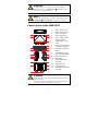
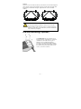
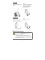
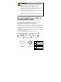
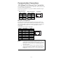
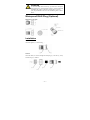
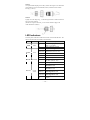
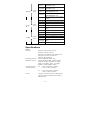
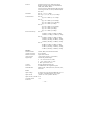
Moxa AirWorks AWK-6222
Quick Installation Guide
First Edition, October 2009
© 2009 Moxa Inc. All rights reserved.
Reproduction without permission is prohibited.
P/N: 1802062220010
Notes for the Reader
WARNING
Indicates that death or personal injury may occur if proper
precautions are not taken.
ATTENTION
Indicates that possible damage to this product or your property
may result if proper precautions are not taken.
NOTE
Highlights important information related to this product.
Package Checklist
Moxa’s AWK-6222 is shipped with the following items. If any of these items
is missing or damaged, please contact your customer service representative for
assistance.
y
y
y
y
y
y
1 AWK-6222
2 Omni-directional antennas (5dBi, N-type (male), 2.4GHz)
1 Quick Installation Guide
1 Software CD
1 Moxa Product Warranty Booklet
1 Accessory Pack (includes wall-mounting kit, screws, field-installable
power plug, field-installable RJ45 plug, DI/DO cap, and Ethernet cap)
NOTE
The items above come with the standard version AWK-6222 The
package contents may vary for customized versions.
Installation
Before installing the AWK-6222, make sure that all items in the Package
Checklist are in the box. In addition, you will need access to a notebook
computer or PC equipped with an Ethernet port. The AWK-6222 has a default
IP address, user name and password that you must use when resetting or
connecting to your AWK-6222 device.
Default IP address: 192.168.127.253
User name: admin
Password: root
Please read “Chapter 2: Getting Started” in the AWK-6222 User’s Manual
for more details about installation and configuration.
— 1 —
ATTENTION
For security reasons, we strongly recommend changing the
password. To do so, go to Maintenance Æ Password, and then
follow the on-screen instructions.
NOTE
To make the change effective, you must save the change and then
click Restart Æ Save and Restart button to apply all changes.
Panel Layout of the AWK-6222
Top Panel View
Front Panel View
1
2
3
4
1.
MAIN 1 antenna port.
2.
MAIN 2 antenna port.
3.
AUX 1 antenna port.
4.
AUX 2 antenna port.
5.
LEDs for PWR, FAULT,
STATE, WLAN1,
5
WLAN2, LAN1, and
LAN2.
Bottom Panel View
8
6
10
7
9
6.
M12 A-coding connector
7.
M12 8-pin connector for
8.
10/100BaseT(X) RJ45
9.
RS-232 console port.
10.
Reset button
11.
Screw holes for wall
12.
Waterproof vent
13.
Grounding screw
14.
Screw holes for DIN-rail
for PWR1 and PWR2.
DI/DO
Side Panel View
3
4
9
11
10
12
2
Port:LAN1 and LAN2
Rear Panel View
mounting
1
3
4
13
mounting
14
ATTENTION
Please DO NOT open or remove vent 12. Removing the seal will
void the warranty.
All exposed connectors, including 1 - 4, 6 - 9, should be tightly
covered by suitable caps when they are not in use.
— 2 —
in
in
Dimensions (unit = mm)
in
in
in
Wall Mounting
In most applications, wall mount provides an easier installation. You will find
it quite easy to mount AWK-6222 on the wall, as illustrated below.
STEP 1:
STEP 2:
Attach the wall-mounting kit with
M4 screws, as shown in the
diagram below.
Mounting the AWK-6222 on the wall
requires 4 screws. Use the AWK-6222
device, with wall-mounting kit attached, as
a guide to mark the correct locations of the
4 screws. The heads of the screws should
be between 5.5mm and 8.5 mm in
diameter, and the shafts should not be
more than 5.0 mm in diameter, as shown
in the figure.
5.5 - 8.5 mm
< 5.0 mm
Do not screw the screws all the way in to the wall—leave a space of about 2
mm to allow room to slide the wall-mounting kit between the wall and the
screws.
ATTENTION
You can test the screw head and shank size by inserting the screw
into one of the keyhole shaped apertures of the wall mounting
plates before it is screwed into the wall.
— 3 —
STEP 3:
Once the screws are fixed into the wall, insert the four screw heads through the
large opening of the keyhole-shaped apertures, and then slide the AWK-6222
downwards, as indicated to the right. Tighten the four screws for added
stability.
⇒
ATTENTION
To avoid environmental vibration or shock, you can consider a
robust installation with four larger screws, in which the shafts are
between 7.0 mm and 8.5 mm in diameter, and fix the AWK-6222
onto wall directly and tightly.
DIN-Rail Mounting (Optional)
The DK-DC50131 die-cast metal kit can be
bought separately, and enable easy and robust
installation for the AWK-6222. A pair of
DK-DC50131s is needed for DIN-Rail
mounting. To install the DIN-Rail mounting
kits, tightly attach the two DIN-Rail mounting
kits on the rear panel of AWK-6222 with 12
screws. (6 screws for each kit)
— 4 —
To Install
STEP 1:
STEP 2:
Use the recessed button on the
spring-loaded bracket to lock it into
position.
Insert the top of the DIN-Rail into
the slot just below the upper hook of
the DIN-Rail mounting kit. Push the
AWK-6222 toward the DIN-Rail
until the DIN-Rail attachment
bracket snaps into place.
To Release
STEP 1:
STEP 2:
Pull out the two spring-loaded
brackets from the bottom until they
are fixed in the “release” position.
Pull the AWK-6222 out and
upward.
Wiring Requirements
WARNING
Safety First!
Be sure to disconnect the power cord before installing and/or
wiring your Moxa AWK-6222.
Calculate the maximum possible current in each power wire and
common wire. Observe all electrical codes dictating the
maximum current allowable for each wire size. If the current goes
above the maximum ratings, the wiring could overheat, causing
serious damage to your equipment.
— 5 —
You should also pay attention to the following items:
y Use separate paths to route wiring for power and devices. If power wiring
and device wiring paths must cross, make sure the wires are perpendicular
at the intersection point.
NOTE: Do not run signal or communications wiring and power wiring in
the same wire conduit. To avoid interference, wires with different signal
characteristics should be routed separately.
y You can use the type of signal transmitted through a wire to determine
which wires should be kept separate. The rule of thumb is that wiring with
similar electrical characteristics can be bundled together.
y Keep input wiring and output wiring separate.
y It is strongly advised that you label wiring to all devices in the system when
necessary.
Grounding Moxa AWK-6222
Grounding and wire routing help limit the effects of noise due to
electromagnetic interference (EMI). Run the ground connection from the
ground screw to the grounding surface prior to connecting devices.
ATTENTION
This product is intended to be mounted to a well-grounded
mounting surface, such as a metal panel. There must be no
potential difference between two ground potentials, otherwise
there is a risk that the device could be destroyed.
Wiring the Redundant Power Inputs
The AWK-6222 must be connected to a power-over-Ethernet (PoE) IEEE
802.3af compliant power source or an IEC60950 compliant limited power
source. When AWK-6222 is powered via DC power, the M12 A-coding
connector on the bottom panel is used for the AWK-6222’s two redundant
inputs. The pin assignment is shown below:
4
3
5
1
2
Pin
1
2
3
4
5
Power Input
V1+
V2+
V1V2GND
— 6 —
ATTENTION
This product is intended to be supplied by a Listed Power Unit
marked “Class 2” or “LPS” and rated O/P: 12 to 48 VDC,
minimum 6 W (12 V/0.494 A to 48V/0.121 A).
Make sure the External Power Adaptor (including power cords
and plug assemblies) provided with the unit is certified and
suitable for use in your country.
Before connecting the AWK-6222 to the DC power inputs, make
sure the DC power source voltage is stable.
Please also note, the PoE networks can not route to the outside
plant.
Wiring the Digital Inputs and Relay
Contact (Digital Output)
The AWK-6222 has two sets of digital input—DI1 and DI2. Each DI
comprises two contacts of the 8-pin M12 connector on the AWK-6222’s
bottom panel. These two digital inputs can be connected to
digital-output-enabled sensors for on-site status monitoring.
The AWK-6222 also has one relay output, which consists of the two contacts.
These relay contacts are used to detect user-configured events. The two wires
attached to the relay contacts form an open circuit when a user-configured
event is triggered. If a user-configured event does not occur, the relay circuit
will be closed.
A field-installable plug, M12A-8PMM-IP68, is recommended for connecting
the AWK-6222’s DIs and relay.
Pin
1
2
3
4
5
6
7
8
— 7 —
Signal
Relay
DI1 I1
DI1 COM_1
DI2 I2
DI2 COM_2
Reserved
Communication Connections
10/100BaseT(X) Ethernet Port Connection
The 10/100BaseT(X) ports located on the AWK-6222’s bottom panel are used
to connect to Ethernet-enabled devices.
The pinouts for both MDI (NIC-type) ports and MDI-X (HUB/Switch-type)
ports are shown below.
MDI Port Pinouts
Pin
1
2
3
6
MDI-X Port Pinouts
Signal
Tx+
TxRx+
Rx-
Pin
1
2
3
6
8-pin RJ45
Signal
Rx+
RxTx+
Tx-
1
8
RS-232 Connection
The AWK-6222 has one RS-232 (8-pin RJ45) console port located on the
bottom panel. Use either an RJ45-to-DB9 or RJ45-to-DB25 cable to connect
the Moxa AWK-6222’s console port to your PC’s COM port. You may then
use a console terminal program to access the AWK-6222 for console
configuration.
Console Pinouts for 10-pin or 8-pin RJ45
10-Pin
1
2
3
4
5
6
7
8
9
10
Description
----DSR
RTS
GND
TxD
RxD
DCD
CTS
DTR
-----
NOTE 1.
2.
8-Pin
1
2
3
4
5
6
7
8
1
8
The pin numbers for male DB9 and DB25 connectors, and
hole numbers for female DB9 and DB25 connectors, are
labeled on the connector. However, the numbers are typically
quite small, so you may need to use a magnifying glass to see
the numbers clearly.
The pin numbers for both 8-pin and 10-pin RJ45 connectors
(and ports) are typically not labeled on the connector (or port).
Refer to the pinout diagram above to see how RJ45 pins are
numbered.
— 8 —
ATTENTION
To ensure the IP68-rated connectivity, you must use a waterproof
housing during any communication activities. An IP68-rated field
installable plug, which is attached in AWK-6222’s accessory
pack, may be needed in this case. The installation guide is shown
below:
Waterproof RJ45 Plug (Optional)
Dimensions (unit: mm)
Installation
STEP 1:
Attach the gasket ① to the housing ③
STEP 2:
Insert the cable (ex. CAT5e) through the clamp ring ④, screw nut ②, seal ⑤
and housing ③, as follows:
— 9 —
STEP 3:
Crimp the modular RJ plug to the cable; (NOTE: the snagless cover shield and
strain-relief boot are not recommended.) Then, assemble the seals and the
housing (③ and ⑤).
STEP 4:
Tightly screw the clamp ring ④ to the housing and check to make sure that the
plug is securely fastened.
(NOTE: for a tighter connection, you can connect the RJ-45 plug to the
AWK-6222 before STEP 4.)
LED Indicators
The front panel of the Moxa AWK-6222 contains several LED indicators. The
function of each LED is described in the table below.
LED
PWR
FAULT
STATE
WLAN 1
Color
Green
Red
State
On
Off
Power is not being supplied.
On
Relay is event-triggered.
Blink (slow)
Cannot get an IP address from the
DHCP server (interval: 1 sec).
Blink (fast)
IP address conflict (interval: 0.5 sec).
Off
Normal status.
Green
Software Ready.
Green/Red Green Blink
Green/
Amber
Description
Power is being supplied (from power
input 1 or 2, or PoE)
The AWK Search Utility has located
the AWK. (interval: 1sec).
Red
Booting or Error condition.
Green On
WLAN is functioning in
Client/Slave mode.
Green Blink
WLAN’s is transmitting data in
Client/Slave mode.
Amber On
WLAN is functioning in
AP/Bridge/Master mode.
Amber Blink
WLAN’s is transmitting data in
AP/Bridge/Master mode.
Off
WLAN is not in use or not working
properly.
— 10 —
WLAN 2
Green/
Amber
Green On
WLAN is functioning in
Client/Slave mode.
Green Blink
WLAN’s is transmitting data in
Client/Slave mode.
Amber On
WLAN is functioning in
AP/Bridge/Master mode.
Amber Blink
WLAN’s is transmitting data in
AP/Bridge/Master mode.
Off
WLAN is not in use or not working
properly.
Yellow On
LAN port’s 10Mbps link is active.
Yellow Blink Data is being transmitted at 10 Mbps.
LAN 1
Yellow/
Green
Yellow Off
LAN port’s 10Mbps link is inactive.
Green On
LAN port’s 100Mbps link is active.
Green Blink
Data is being transmitted at 100
Mbps.
Green Off
LAN port’s 100Mbps link is inactive.
Yellow On
LAN port’s 10Mbps link is active.
Yellow Blink Data is being transmitted at 10 Mbps.
LAN 2
Yellow/
Green
Yellow Off
LAN port’s 10Mbps link is inactive.
Green On
LAN port’s 100Mbps link is active.
Green Blink
Data is being transmitted at 100
Mbps.
Green Off
LAN port’s 100Mbps link is inactive.
Specifications
WLAN
Standards
Spread Spectrum and
Modulation (Typical)
Operating Channels
(Central Frequency)
Security
IEEE 802.11a/g/b for Wireless LAN
IEEE 802.11i Wireless Security
IEEE 802.3u 10/100BaseT(X) for Ethernet LAN
EEE 802.3af for Power-over-Ethernet
IEEE 802.1D/w STP/RSTP
DSSS with DBPSK, DQPSK, CCK
OFDM with BPSK, QPSK, 16QAM, 64QAM
64QAM @ 54 Mbps, 16QAM @ 24/36 Mbps,
QPSK @ 12/18 Mbps, CCK @ 11/5.5 Mbps,
DQPSK @ 2 Mbps, DBSK@ 1 Mbps
US:
2.412 to 2.462 GHz (11 channels)
5.18 to 5.24 GHz (4 channels)
EU:
2.412 to 2.472 GHz (13 channels)
5.18 to 5.24 GHz (4 channels)
64-bit and 128-bit WEP encryption, WPA /WPA2
Personal or Enterprise (IEEE 802.1X/ RADIUS,
TKIP and AES)
— 11 —
Protocol
General Protocols: Proxy ARP, DNS, HTTP,
HTTPS, IP, ICMP, SNTP, TCP, UDP, RADIUS,
SNMP, RTP, PPPoE, DHCP
AP-only Protocols: ARP, BOOTP, DHCP, dynamic
VLAN-Tags for 802.1X-Clients, STP/RSTP (IEEE
802.1D/w)
Data Rates
802.11b: 1, 2, 5.5, 11 Mbps
802.11a/g: 6, 9, 12, 18, 24, 36, 48, 54 Mbps
802.11b:
Typ. 23±1.5 dBm @ 1 to 11 Mbps
802.11g:
Typ. 18±1.5 dBm @ 6 to 24 Mbps,
Typ. 16±1.5 dBm @ 36 to 48 Mbps,
Typ. 15±1.5 dBm @ 54 Mbps
802.11a:
Typ. 20±1.5 dBm @ 6 to 24 Mbps,
Typ. 19±1.5 dBm @ 36 Mbps,
Typ. 18±1.5 dBm @ 48 Mbps,
Typ. 17±1.5 dBm @ 54 Mbps
802.11b:
-97 dBm @ 1 Mbps, -94 dBm @ 2 Mbps,
-92 dBm @ 5.5 Mbps, -90 dBm @ 11 Mbps
802.11g:
-93 dBm @ 6 Mbps, -91 dBm @ 9 Mbps,
-90 dBm @ 12 Mbps, -88 dBm @ 18 Mbps,
-84 dBm @ 24 Mbps, -80 dBm @ 36 Mbps,
-76 dBm @ 48 Mbps, -74 dBm @ 54 Mbps
802.11a:
-90 dBm @ 6 Mbps, -89 dBm @ 9 Mbps,
-89 dBm @ 12 Mbps, -85 dBm @ 18 Mbps,
-83 dBm @ 24 Mbps, -79 dBm @ 36 Mbps,
-75 dBm @ 48 Mbps, -74 dBm @ 54 Mbps
Transmit Power
Receiver Sensitivity
Interface
Default Antenna
Antenna Connector
DI/DO Connection
Alarm Contact
Digital Input
Console
LAN Port
LED Indicators
2.4GHz, 5dBi, Omni-directional antenna
N-type (female)
8-pole M12 connector
1 relay output (capacity: 1A @24VDC)
2 electrically-isolated inputs
y +3 to -30V for state “0” (OFF)
y +13 to +30V for state “1” (ON)
y Max. input current: 8 mA
RS-232 (Waterproof RJ45 type)
10/100BaseT(X) auto negotiation speed
PWR, FAULT, STATE, WLAN1, WLAN2, LAN1,
and LAN2
Power
Input Voltage
48 VDC Power-over-Ethernet (IEEE 802.3af) or 12
to 48 VDC, redundant dual DC power inputs
Input Current
(1.066A to 0.312A @12VDC-48VDC)
Input Current @ 24VDC 0.3 A
Overload Current
1.6 A
Protection
— 12 —
Reverse Polarity
Protection
Mechanical
Casing
Dimensions
Weight
Installation
Environmental
Operating Temperature
Storage Temperature
Ambient Relative
Humidity
Present
IP68 protection, aluminum case
224 x 147.7 x 66.5 mm (8.82 x 5.82 x 2.62 in)
1.8 kg
Wall Mounting, or DIN-Rail mounting
-40 to 75°C (-40 to 167°F)
-40 to 85ºC (-40 to 185ºF)
5 to 100% (non-condensing)
Regulatory Approvals*
Safety
EN60950-1, UL60950-1
Radio
EN300 328, EN301 893
EMC
EN301 489-1/-17, FCC Part 15, EN55022/55024,
IEC61000-6-2/-4
Environmental/EMC
EN50155, EN50121-1/-4
compliancy
* Please check Moxa’s website for the most up-to-date certification status.
WARRANTY
5 years
Details: See http://www.moxa.com/warranty
ATTENTION
The AWK-6222 is NOT a portable mobile device and should be
located 20cm away from the human body.
The AWK-6222 is NOT designed for the general public. A
well-trained technician is required to safely deploy AWK-6222s
and establish a wireless network..
ATTENTION
Use the antennas correctly: The 2.4GHz antennas are needed
when AWK-6222 operates in IEEE 802.11b/g. The 5GHz
antennas are needed for IEEE802.11a. Make sure your antenna
installation is within a safety area, which is covered by a lightning
protection or surge arrest system.
— 13 —
Technical Support Contact Information
www.moxa.com/support
Moxa Americas:
Toll-free: 1-888-669-2872
Tel:
+1-714-528-6777
Fax:
+1-714-528-6778
Moxa China (Shanghai office):
Toll-free: 800-820-5036
Tel:
+86-21-5258-9955
Fax:
+86-10-6872-3958
Moxa Europe:
Tel:
+49-89-3 70 03 99-0
Fax:
+49-89-3 70 03 99-99
Moxa Asia-Pacific:
Tel:
+886-2-8919-1230
Fax:
+886-2-8919-1231
— 14 —