1
Grid Director 4036/2036
Installation Manual
DOC-00467 A09
www.mellanox.com
NOTE:
MELLANOX TECHNOLOGIES, INC. AND ITS AFFILIATES ("MELLANOX") FURNISH THIS DOCUMENT "AS IS," WITHOUT
WARRANTY OF ANY KIND. MELLANOX DISCLAIMS ALL WARRANTIES, EXPRESS OR IMPLIED, INCLUDING, WITHOUT
LIMITATION, THE IMPLIED WARRANTIES OF MERCHANTABILITY, FITNESS FOR A PARTICULAR PURPOSE,
NON-INFRINGEMENT AND THOSE ARISING FROM A COURSE OF PERFORMANCE, A COURSE OF DEALING, OR TRADE
USAGE. MELLANOX SHALL NOT BE LIABLE FOR ANY ERROR, OMISSION, DEFECT, DEFICIENCY OR NONCONFORMITY IN
THIS DOCUMENT AND DISCLAIMS ALL LIABILITY, INCLUDING LIABILITY FOR INFRINGEMENT OF ANY INTELLECTUAL
PROPERTY RIGHTS RELATED TO THE INFORMATION CONTAINED IN THIS DOCUMENT.
No license, expressed or implied, to any intellectual property rights is granted under this document. This document, as well as the software
described in it, are furnished under a separate license and shall only be used or copied in accordance with the terms of the applicable license. The
information in this document is furnished for informational use only, is subject to change without notice, and should not be construed as any
commitment by Mellanox. Except as permitted by the applicable license, no part of this document may be reproduced, stored in a retrieval
system, or transmitted in any form or by any means without the express written consent of Mellanox.
Names and logos identifying products of Mellanox in this document are registered trademarks or trademarks of Mellanox. Voltaire is a
registered trademark of Mellanox Technologies, Ltd. All other trademarks mentioned in this document are the property of their respective
owners.
Copyright © 2011 Mellanox Technologies, Inc. All rights reserved.
Mellanox Technologies, Inc.
Mellanox Technologies Ltd
350 Oakmead Parkway Suite 100
PO Box 586 Hermon Building
Sunnyvale, CA 94085
Yokneam 20692
U.S.A.
Israel
www.mellanox.com
Tel: +972-4-909-7200
Tel: (408) 970-3400
Fax: +972-4-959-3245
Fax: (408) 970-3403
© Copyright 2011. Mellanox Technologies. All rights reserved.
Mellanox®, BridgeX®, ConnectX®, CORE-Direct®, InfiniBridge®, InfiniHost®, InfiniScale®, PhyX®, Virtual Protocol Interconnect and
Voltaire are registered trademarks of Mellanox Technologies, Ltd.
FabricIT, MLNX-OS and SwitchX are trademarks of Mellanox Technologies, Ltd.
All other trademarks are property of their respective owners.
2
Document Number: DOC-00467 A09
Contents
Contents
Preface .................................................................................................................................................... 7
1
2
3
4
5
Introduction ..................................................................................................................................... 9
1.1
4036/2036 Switch Overview ................................................................................................... 9
1.2
4036/2036 Switch Main Features ......................................................................................... 10
1.3
Management ......................................................................................................................... 10
Unpacking ...................................................................................................................................... 11
2.1
Package Contents ................................................................................................................ 11
2.2
Unpacking the 4036/2036 Switch ......................................................................................... 11
2.3
Rail Kit (KIT-00008) .............................................................................................................. 13
2.4
Multipurpose (Mng) Console Cable Kit ................................................................................. 14
2.5
Packing the 4036/2036 Switch ............................................................................................. 14
Getting Started .............................................................................................................................. 16
3.1
Front Panel Description ........................................................................................................ 16
3.2
Rear Panel Description ......................................................................................................... 17
Product Options ............................................................................................................................ 19
4.1
4036/2036 Switch Available Configurations ......................................................................... 19
4.2
InfiniBand Clusters Using the 4036/2036 Switch ................................................................. 19
4.3
Ordering Information ............................................................................................................. 22
Technical Specifications and Certifications .............................................................................. 24
5.1
4036/2036 Switch Technical Specifications ......................................................................... 24
5.2
Power Specifications - Power Supply Module ...................................................................... 25
5.3
Certifications ......................................................................................................................... 26
5.4
Gost-R Certification .............................................................................................................. 27
5.5
Declarations .......................................................................................................................... 27
5.5.1
Declaration of Conformity ....................................................................................... 27
5.5.2
Hazardous Substances (RoHS 5) Compliance Declaration ................................... 27
5.6
Label(s) ................................................................................................................................. 28
5.7
Shock and Vibration ............................................................................................................. 29
5.8
Chassis Clearance Requirements ........................................................................................ 29
5.9
Weights and Dimensions ...................................................................................................... 29
5.10 Acoustic Data........................................................................................................................ 29
5.11 Export Information ................................................................................................................ 30
5.12 Shipping Restrictions ............................................................................................................ 30
6
Hardware Installation .................................................................................................................... 31
6.1
Installation Options ............................................................................................................... 31
3
Contents
6.1.1
7
Cooling .................................................................................................................... 31
6.2
Required Tools ..................................................................................................................... 31
6.3
Site Planning......................................................................................................................... 32
6.3.1
Rack and Clearance Requirements ........................................................................ 32
6.3.2
Site Environment Specification ............................................................................... 32
6.3.3
Power Requirements .............................................................................................. 32
6.3.4
Site Preparation Checklist ...................................................................................... 33
6.4
Measuring the Distance between Mounting Rails ................................................................ 33
6.5
Assembling and Mounting the Rail ....................................................................................... 33
6.5.1
Rail Kit..................................................................................................................... 33
6.5.2
Option 1 .................................................................................................................. 35
6.5.3
Option 2 .................................................................................................................. 42
6.6
4036/2036 Switch Power Up ................................................................................................ 47
6.7
Field Replaceable Units ........................................................................................................ 48
6.7.1
Fan Unit .................................................................................................................. 48
6.7.2
Power Supplies ....................................................................................................... 48
Cabling ........................................................................................................................................... 50
8
7.1
Cabling Guide Bracket Installation ....................................................................................... 50
7.2
InfiniBand Cabling - QDR ..................................................................................................... 52
7.3
Multipurpose Management (Mng) Console Cable ................................................................ 53
Operation ....................................................................................................................................... 55
9
8.1
Powering on the 4036/2036 Switch ...................................................................................... 55
8.2
4036/2036 Switch LED Indicators ........................................................................................ 56
8.3
Where to Go Next ................................................................................................................. 57
Troubleshooting ............................................................................................................................ 58
9.1
Overview ............................................................................................................................... 58
9.2
Solving Startup Problems ..................................................................................................... 58
9.3
Preparation before Contacting Customer Service ................................................................ 58
Appendix A:
A.1
A.2
Unpacking the 4036/2036 Switch ......................................................................................... 59
A.1.1
Multipurpose Console Cable Kit ............................................................................. 60
A.1.2
Packing the Switch ................................................................................................. 60
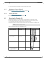
Mounting the iDataplex Kit .................................................................................................... 60
Appendix B:
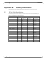
Cabling Information .............................................................................................. 64
B.1
IB Port Cable Specifications ................................................................................................. 64
B.2
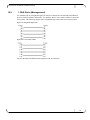
1 GbE Ports (Management) .................................................................................................. 65
Appendix C:
4
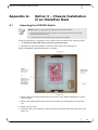
Option 3 – Chassis Installation in an iDataPlex Rack ....................................... 59
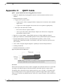
QSFP Cable ........................................................................................................... 66
Contents
List of Figures
Figure 1: 4036/2036 Front View .............................................................................................................. 9
Figure 2: 4036/2036 Rear View ............................................................................................................... 9
Figure 3: 4036/2036 Cardboard Package (Open) - Standard ............................................................... 12
Figure 4: Removing the 4036/2036 Switch from the Cardboard Package ............................................ 13
Figure 5: Fixed Rail (KIT-00008) ........................................................................................................... 14
Figure 6: Packing the 4036/2036 Switch ............................................................................................... 15
Figure 7: 4036/2036 Front Panel ........................................................................................................... 16
Figure 8: InfiniBand Cluster Using 4036 Switch Single-hop Configuration ........................................... 20
Figure 9: InfiniBand Cluster Using 2036 Switch Single-hop Configuration ........................................... 20
Figure 10: InfiniBand Cluster Using 4036/2036 Switch Three-hop Configuration ................................. 22
Figure 11: 4036 Label (Example) .......................................................................................................... 28
Figure 12: 2036 Label (Example) .......................................................................................................... 28
Figure 13: 4036/2036 – Option 1 Assembly .......................................................................................... 35
Figure 14: Mounting the long bracket .................................................................................................... 36
Figure 15: Positioning and aligning the mounting bar and long bracket ............................................... 36
Figure 16: Securing the mounting bar ................................................................................................... 36
Figure 17: Installing the clip nuts and placing the power cord .............................................................. 37
Figure 18: Inserting the switch into the rack .......................................................................................... 37
Figure 19: Power cord over the long bracket ........................................................................................ 38
Figure 20: Securing power cords .......................................................................................................... 38
Figure 21: Connecting the power cables ............................................................................................... 38
Figure 22: Secure the long brackets to the rack rail .............................................................................. 39
Figure 23: Mounting the short bracket ................................................................................................... 39
Figure 24: Adjusting the short bracket ................................................................................................... 40
Figure 25: Securing Screws and Brackets ............................................................................................ 40
Figure 26: Switch mounted in a rack – Rack rear view ......................................................................... 40
Figure 27: Switch mounted in a rack – Rack front view ........................................................................ 41
Figure 28: 4036/2036 – Option 2 Assembly .......................................................................................... 42
Figure 29: Mounting the short bracket ................................................................................................... 43
Figure 30: Mounting the long bracket .................................................................................................... 43
Figure 31: Positioning and aligning the mounting bar and long bracket ............................................... 44
Figure 32: Securing the rail ................................................................................................................... 44
Figure 33: Placing the clip nuts on the vertical rack rails ...................................................................... 45
Figure 34: Insert the switch into the rack ............................................................................................... 45
Figure 35: Secure the rack screws ........................................................................................................ 45
Figure 36: Installing the long bracket .................................................................................................... 46
Figure 37: Securing the rack screws ..................................................................................................... 46
Figure 38: Securing the long bracket screws to the mounting bar ........................................................ 47
Figure 39: Switch mounted in a rack – Rack front view ........................................................................ 47
Figure 40: Replacing the Fan ................................................................................................................ 48
Figure 41: Replacing the Power Supply ................................................................................................ 49
Figure 42: Cabling Guide Bracket (CG-24) ........................................................................................... 50
5
Contents
Figure 43: Installing a Cabling Guide Bracket ....................................................................................... 51
Figure 44: Installing a Cabling Guide Bracket (sliding rail) ................................................................... 51
Figure 45: Cable Management .............................................................................................................. 52
Figure 46: Cabling ................................................................................................................................. 52
Figure 47: 4036/2036 Cardboard Package (Open) - Standard ............................................................. 59
Figure 48: 4036/2036 – Assembly in an iDataplex Rack ...................................................................... 61
Figure 49: Attaching the mount bracket ................................................................................................ 61
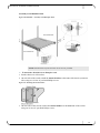
Figure 50: Securing clip nuts and the mount plates onto the rack ........................................................ 62
Figure 51: Inserting the mount holder into the mount plate ................................................................... 63
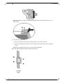
Figure 52: Securing the front of the chassis .......................................................................................... 63
Figure 53: Straight-through Cables ....................................................................................................... 65
Figure 54: Cross-connect Cables .......................................................................................................... 65
Figure 55: QSFP Connector-Dimensions .............................................................................................. 66
Figure 56: QSFP Connector .................................................................................................................. 67
List of Tables
Table 1: 4036/2036 Front Panel Components ...................................................................................... 16
Table 2: Rear Panel Components ......................................................................................................... 18
Table 3: 4036/2036 Switch Ordering Information .................................................................................. 22
Table 4: 4036/2036 Module Ordering Information................................................................................. 23
Table 5: 4036/2036 Switch Packing List (According to Configuration) ................................................. 23
Table 6: 4036/2036 Switch Technical Data ........................................................................................... 24
Table 7: Power Supply Module Data ..................................................................................................... 25
Table 8: Clearance Requirements ......................................................................................................... 29
Table 9: Unpacked Weights & Dimensions ........................................................................................... 29
Table 10: Packed Weights & Dimensions ............................................................................................. 29
Table 11: Materials and Tools Required ............................................................................................... 31
Table 12: Site Preparation Checklist ..................................................................................................... 33
Table 13: Rail Kit (P/N KIT-00008) Detailed Part List ........................................................................... 34
Table 14: 4036/2036 Switch LED Indications ........................................................................................ 56
Table 15: iDataplex Mounting Kit (P/N KIT-00004) Part List ................................................................. 60
Table 16: 4X InfiniBand Port Cabling Specifications ............................................................................. 64
6
Grid Director 4036/2036 Installation Manual
Preface
About this Manual
This manual provides installation instructions for the Voltaire high-bandwidth, low-latency
scalable 36-port InfiniBand 4036 QDR and 2036 DDR chassis. It includes the product
specifications, unpacking and installation information, unit power up, and initiation and
troubleshooting procedures.
Refer to the official and latest product release notes for last-minute updates.
Technical support may be obtained directly from:
Your regional distributor from whom this product was ordered
Your OEM customer representative
For further information and assistance, go to
http://www.mellanox.com/content/pages.php?pg=support_index.
Audience
The manual is intended primarily for system administrators who are authorized to install a
4036 or a 2036 system.
It is assumed that the readers are familiar with the InfiniBand technology and terminology.
Related Documentation
For additional information, refer to the following documents:
Grid Director Family Getting Started Guide [LIT-00037]
Grid Director Family User Manual [DOC-00785]
Grid Director Family Release Notes [DOC-00962]
Regulatory and Compliance Reference Guide [DOC-00859]
Document Conventions
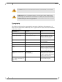
The following lists conventions used in this document.
NOTE: Identifies important information that contains helpful suggestions.
7
Preface
CAUTION: Alerts you to the risk of personal injury, system damage, or loss of data.
WARNING: Warns you that failure to take or avoid a specific action might result in
personal injury or a malfunction of the hardware or software. Be aware of the hazards
involved with electrical circuitry and be familiar with standard practices for preventing
accidents before you work on any equipment.
Typography
The following table describes typographical conventions in Mellanox documentation. All
terms refer to isolated terms within body text or regular table text unless otherwise mentioned
in the Notes column.
Term, Construct,
Text Block
Example
File name, pathname
/opt/ufm/conf/gv.cfg
Console session (code)
-> flashClear <CR>
Notes
Complete sample line or block.
Comprises both input and output.
The code can also be shaded.
8
Linux shell prompt
#
The "#"character stands for the
Linux shell prompt.
Mellanox CLI Guest Mode
Switch >
Mellanox CLI Guest Mode.
Mellanox CLI admin mode
Switch #
Mellanox CLI admin mode
String
< > or []
Strings in < > or [ ] are descriptions
of what will actually be shown on the
screen, for example, the contents of
<your ip> could be 192.168.1.1
Management GUI label, item
name
New Network,
New Environment
Management GUI labels and item
names appear in bold, whether or not
the name is explicitly displayed (for
example, buttons and icons).
User text entered into Manager,
e.g., to assign as the name of a
logical object
"Env1", "Network1"
Note the quotes. The text entered
does not include the quotes.
Grid Director 4036/2036 Installation Manual
1
Introduction
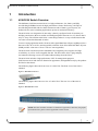
1.1
4036/2036 Switch Overview
The Mellanox Grid Director 4036/2036 is a high performance, low latency and fully
non-blocking InfiniBand switch for high performance clusters. Delivering 2.88 Tbps of
non-blocking bandwidth with less than 100 nanoseconds of latency (port-to-port), I/O
bottlenecks are removed making applications operate at maximum efficiency.
The 4036/2036 was designed to fit into today’s densely configured racks. It has thirty-six
40Gbps ports that use the new smaller and intelligent QSFP connector in a 1U chassis that is
only 15" deep. The efficient 4036/2036’s smart design makes it is easy to build clusters that
can scale-out into the thousands of nodes.
To meet varying application needs, the 4036 offers Quad Data Rate 4X ports (QDR provides a
date rate of 40, 20 or 10 Gb/s auto-negotiable) while the 2036 offers Dual Data Rate 4X ports
(DDR provides a data rate of 20 or 10 Gb/sec auto-negotiable).
The 4036/2036 switch incorporates redundant, hot-swappable power supplies for High
Availability, as well as a hot-swappable fan unit. The 4036/2036 offers a plug-and-play
environment, allowing servers to be added without taking down the fabric.
The 4036/2036 includes a high-performance CPU for management purposes.
Grid Directors 2036 and 4036 are identical in appearance, distinguishable only by the product
ID label on the chassis.
The following figure shows the front view of a 4036 Unit. The front view of the 2036 is
identical.
Figure 1: 4036/2036 Front View
The following figure shows the rear view of a 4036 Unit. The rear view of the 2036 is
identical.
Figure 2: 4036/2036 Rear View
NOTE: The 2036 and 4036 switches are identical in appearance. Therefore, the graphic
representations are generic and are applicable to either switch.
9
Introduction
1.2
4036/2036 Switch Main Features
Thirty-Six auto-negotiating QSFP InfiniBand ports in a 1U chassis:
The 4036 switch is equipped with QDR ports (40 Gbps per port)
The 2036 switch is equipped with DDR ports (20 Gbps per port)
1Ux19"x15" non blocking standalone switch using a single switch chip
QSFP ports supporting any type of cable, Copper or Optical.
High performance, low power CPU for device management
Ultra low latency under 100 ns (nanoseconds)
Available aggregate bandwidth of up to 2.88 Tbps (QDR), 1440 Gbps (DDR), or 720 Gbps
(SDR)
Architected to provide high MTBF
Redundant, hot-swappable power supplies
Front-to-back or back-to-front hot-swappable fan unit.
QSFP InfiniBand ports supporting copper or optical cables and adapters
Built-in cable detection and optimization to achieve the longest available cable distance
and highest performance
Built-in high availability
1.3
Management
The Grid Director 4036/2036 includes smart device management that provides a simple
interface for deploying, troubleshooting, maintaining and upgrading the switch. With a simple
to use CLI interface, routine tasks such as monitoring the switch’s operation or upgrading
software and firmware are made simple.
The Grid Director 4036 comes with an onboard subnet manager, enabling simple,
out-ofthe-box fabric bring-up for small to medium clusters.
Refer to the 4036/2036 User Manual for details on 4036/2036 software requirements and
configuration.
Chapter 1
10
Grid Director 4036/2036 Installation Manual
2
Unpacking
2.1
Package Contents
The 4036/2036 switch is supplied in a cardboard box. The switch is delivered with either one
or two pre-installed hot-swappable power supplies (according to configuration) and one
hot-swappable fan unit.
Additional components include:
Two power cords (one per power supply)
Rail kit (for details, see Rail Kit (KIT-00008) (on page 13))
A multipurpose console cable kit (Mng)
Getting Started Guide
A product CD containing 4036/2036 switch documentation and software
Before unpacking, make sure that the box is sealed and undamaged.
Before beginning the installation of the 4036/2036 switch, verify that the package contains the
items detailed in the packing list.
Check for loose parts or any visible damage to the contents. Notify your supplier if you
detected damaged or missing parts.
2.2
Unpacking the 4036/2036 Switch
This section details the 4036/2036 package contents and provides instructions on how to
unpack the chassis.
The iDataPlex Rail Kit and packaging are detailed in Option 3 – Chassis Installation in an
iDataPlex Rack (on page 59).
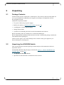
To unpack the 4036/2036 chassis
1. Open the box and check that it contains the items as shown.
11
Unpacking
Figure 3: 4036/2036 Cardboard Package (Open) - Standard
NOTE: Keep the original packing materials; they will be needed if:
The product needs to be moved. For example if it is staged at one location before being
delivered at the production site.
A module needs to be returned for repair, replacement, or upgrade.
2. Remove the box containing the Rail Kit, the Power Cords, and the multipurpose console
cable kit (Mng).
3. Remove the Getting Started Guide which also contains the Product CD.
4. Remove the top foam.
12
Grid Director 4036/2036 Installation Manual
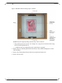
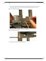
5. Carefully remove the 4036/2036 switch. Use the dedicated niche to lift the switch, as
shown in the following figure.
Figure 4: Removing the 4036/2036 Switch from the Cardboard Package
6. Remove the protective antistatic bag from the 4036/2036 switch.
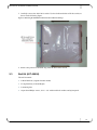
2.3
Rail Kit (KIT-00008)
The rail kit entails:
2 Short Brackets (Angular bracket mount)
2 Long Brackets (Left and Right)
2 mounting bars
14 pan head Philips screws, 8-32 x 1/4" with tooth lock washers and nylon patch
13
Unpacking
Figure 5: Fixed Rail (KIT-00008)
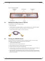
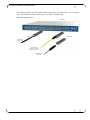
2.4
Multipurpose (Mng) Console Cable Kit
The multipurpose console kit (Mng) contains:
RJ45 to RJ45 cable
A RJ45 to DB-9 cross-adaptor for RS-232 console connection (CLI). (The DB-9 adaptor
has a number 26 printed on it. This means that pins 2 and 6 are crossed).
A RJ45 to DB-9 adaptor for RS-232 console connection
2.5
Packing the 4036/2036 Switch
You may need to move the 4036/2036 switch to a different location or send it for repair;
should this be necessary, pack the equipment as described below.
To pack the 4036/2036 chassis
1. Unmount the 4036/2036 switch from the rack.
2. Dissassemble the rail brackets and pack the parts in the rail kit box.
3. Insert the 4036/2036 switch into its antistatic bag.
4. Carefully lift the switch, making sure that the bottom of the switch is facing down. Tip: you
can easily identify the bottom of the switch since it has a certification label.
5. Check the niches in the bottom foam to make sure that you are inserting the switch in the
correct direction as shown in the following figure. Note that the ID Tag is fragile and could
bend, use extra caution.
14
Grid Director 4036/2036 Installation Manual
Figure 6: Packing the 4036/2036 Switch
6. Insert the switch into the cardboard box and place it on the bottom foam.
7. Place the top foam on top of the switch.
8. Slide the rail kit box in the dedicated niche alongside of the switch, as shown in the
illustration in Unpacking the Switch (on page 59).
IMPORTANT NOTE: When sending the switch for repair without the rail kit, it is still
important to secure the switch by filling this niche with a filler. This will protect the switch
and prevent it from moving during transportation.
9. Place the Getting Started Guide and the Multipurpose Console Kit (Mng) on top of the top
foam as shown in the illustration in Unpacking the Switch (on page 59).
10.Place the power cords in the allocated spaces in the foam, as shown in the illustration in
Unpacking the Switch (on page 59).
11.Use tape to close the box and verify that the box is securely closed.
Chapter 2
15
Getting Started
3
Getting Started
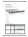
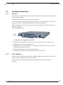
3.1
Front Panel Description
This section details the front panel 4036/2036 chassis.
Figure 7: 4036/2036 Front Panel
1. Swappable power supply modules
2. LEDs:
System power
Info LED
SM
Fan unit
Power supply
3. AC power inlet
4. Reset Button
5. Swappable fan unit
Table 1: 4036/2036 Front Panel Components
Component
4036 /2036 No.
of components
Function
Power Supply (PSU)
1 or 2 (according
to configuration)
Provides the 4036/2036 DC supply. One or two AC/DC
100-240Vac to 12Vdc 350W hot-swappable redundant
power supplies are installed in the 4036/2036 switch. The
power supply has an IEC Power Receptacle that supplies the
4036/2036 input voltage, as indicated in the power supply
characteristics in Power Specifications - Power Supply
Module (on page 25).
Fan Unit
1
Hot swappable fan unit hosting three internal fans for high
availability. Auto-heat sensing to allow for silent fan
operation
Two options are available:
Front-to-rear cooling (labeled as "Air-in")
Rear-to-front cooling (labeled as "Air-out")
16
Grid Director 4036/2036 Installation Manual
Component
4036 /2036 No.
of components
Function
Reset Button
1
When pressed for more than 1 second, resets the entire unit.
LEDs (Status Indicators)
5
System Power – Chassis power OK LED - ON/OFF
Info LED – User-defined LED for management use. Sets
the Info LED on a desired module. When you enable this
LED through the GUI or CLI, you can go on site and
immediately physically locate the module.
SM – Subnet Management (active or standby)
Fan Unit – Fan indication. Turns off as a result of fan
failure
Power Supply – Power indication. Turns off as a result
the failure of the power supply unit
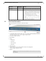
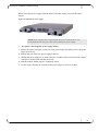
3.2
Rear Panel Description
This section details the rear panel of a 4036/2036 chassis.
1. 36 InfiniBand QDR (Quad Data Rate) ports using standard QSFP InfiniBand Connectors
and LEDs supporting copper, active copper or optical cables.
2. CLI (RS-232) DB9 Connector
3. Reset Button
4. LEDs
PWR LED
Info LED
PS/FAN LED
SM LED
5. USB Connector
6. Gigabit Ethernet auto-negotiating RJ45 Connector for management
1Gbps/100Mbps/10Mbps (& LED)
7. ID Tab
NOTE: Port #1 is located at the bottom left hand side of the rear panel, Port #36 at the top
right hand side.
17
Getting Started
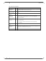
Table 2: Rear Panel Components
Component
No.
Function
InfiniBand Port
Connector
36
4X QSFP InfiniBand connectors for passive copper cables, active copper cables,
active optical cables, and connect optical cables.
InfiniBand Port
Indicators (LEDs)
64
Indicates the physical and logical status of each InfiniBand port. (2 LEDs per
port)
RS232 serial
interface
1
D-sub -9 pin connector (serial interface) for CLI
10/100/1000
Ethernet port
1
Gigabit Ethernet auto-negotiating RJ-45 Connector for management
1Gbps/100Mbps/10Mbps (& LED). Provides out-of-band management interface
over a local network.
4
1 Pwr – System power status
RJ-45 Connector
LEDs (Status
Indicators)
1 PS/FAN LED
1 Info LED – Indicates the unit physical location (user-defined)
1 SM LED
Chassis reset
button
1
When pressed for more than 1 second, resets the entire unit.
USB connector
(Type A)
1
One USB 2.0 Host interface allows you to increase the CPU flash memory by a
connection to a standard Disk-On-Key device.
ID Tab
1
Includes the Switch Part and Serial Numbers
Chapter 3
18
Grid Director 4036/2036 Installation Manual
4
Product Options
4.1
4036/2036 Switch Available Configurations
The Grid Director 4036/2036 is a 1U entry level 36 InfiniBand 4X ports switch, providing
bidirectional 40 Gbps/20 Gbps per port grid connectivity, potentially serving as an edge switch
in large fabrics (where the 4036/2036 is serving as core switch) or as a standalone managed
unit in smaller clusters.
4.2
InfiniBand Clusters Using the 4036/2036 Switch
The Grid Director 4036/2036 switch is designed as a standalone unit or as a building block for
larger clusters.
19
Product Options
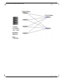
The following figures show a simple 36-server single-hop non-blocking configuration using a
single 4036/2036 switch.
Figure 8: InfiniBand Cluster Using 4036 Switch Single-hop Configuration
Figure 9: InfiniBand Cluster Using 2036 Switch Single-hop Configuration
The following figures show a triple-hop non-blocking configuration, based on multiple
4036/2036 switches functioning as the cluster building blocks.
20
Grid Director 4036/2036 Installation Manual
21
Product Options
The following figures show another example of a three-hop non-blocking configuration, based
on multiple 4036/2036 functioning as the cluster building block.
Figure 10: InfiniBand Cluster Using 4036/2036 Switch Three-hop Configuration
4.3
Ordering Information
Table 3: 4036/2036 Switch Ordering Information
22
Number
Name
Description
VLT-30113
Grid Director 2036 2PS
2036 1U 36 port DDR Switch, front-to-back cooling,
dual PS
VLT-30013
Grid Director 2036 2PS
2036 1U 36 port DDR Switch, back-to-front cooling,
dual PS
VLT-30114
Grid Director 2036 1PS
2036 1U 36 port QDR Switch, front-to-back cooling,
single PS
VLT-30111
Grid Director 4036 2PS
4036 1U 36 port QDR Switch, front-to-back cooling,
dual PS
VLT-30011
Grid Director 4036 2PS
4036 1U 36 port QDR Switch, back-to-front cooling,
dual PS
VLT-30112
Grid Director 4036 1PS
4036 1U 36 port QDR Switch, front-to-back cooling,
single PS
Grid Director 4036/2036 Installation Manual
Number
Name
Description
VLT-30015
Grid Director 4036 1PS
4036 1U 36 port QDR Switch, back-to-front cooling,
single PS
Table 4: 4036/2036 Module Ordering Information
Number
Name
Description
VLT-30029-F
PS-36 AC FRU
PS-36 AC, FRU
VLT-30030-F
FAN-1U Unit Back-To-Front
FRU
FAN-1U unit back-to-front cooling, FRU
VLT-30031-F
FAN-1U Unit Front-to-Back
FRU
FAN-1U unit front-to-back cooling, FRU
KIT-00008
Rail Kit
KIT-00004
iDataPlex Mounting Kit
(Not part of the standard packing list)
510K00022-F
CG-24
Cabling guide bracket kit (Not part of the standard
packing list)
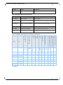
Table 5: 4036/2036 Switch Packing List (According to Configuration)
Getting Started Guide hard
copy
Product CD (documentation &
software)
Multipurpose Mngmnt console
cable kit
Cabling guide bracket kit
iDataPlex rail kit
Rail kit
Fan unit
Air out
2036 (1 PS)
Fan unit
2036 (2 PS)
Air in
4036 (1 PS)
Power cord, PDU plug
4036 (2 PS)
P/N
Power supply unit
Chassis
Fan
Unit
1U
Fan
Unit
1U
2
-
1
-
1
*
1
1
1
2
2
1
-
1
-
*
1
1
1
VLT-30112
1
2
1
-
1
-
*
1
1
1
VLT-30015
1
2
-
1
-
1
*
1
1
1
VLT-30013
2
2
-
1
-
1
*
1
1
1
VLT-30113
2
2
1
-
1
-
*
1
1
1
VLT-30114
1
1
1
-
1
-
*
1
1
1
PSU-1U
PowerC
ord
VLT-30011
2
VLT-30111
KIT0008
KIT
-000 CG-24 Mng
4
( )
* Optional
Chapter 4
23
Technical Specifications and Certifications
5
Technical Specifications and Certifications
5.1
4036/2036 Switch Technical Specifications
Table 6: 4036/2036 Switch Technical Data
Features
Details
Grid Director
4036/2036 General
19-inch front or rear rack mountable chassis, height: 1U, depth: 15"
InfiniBand Ports
36 QSFP interfaces
4036 with Quad Data Rate (QDR) 40 Gbps ports
2036 with Double Data Rate (DDR) 20 Gbps ports
36 4X Quad Data Rate ports (QDR – 40 or 20 or 10 Gbps auto-negotiate)
36 4X Dual Data Rate ports (DDR - 20 or 10 Gbps auto-negotiate)
36 4X Single Data Rate (SDR - 10 Gbps)
Interconnect options: QSFP passive and/or active copper /fibre optic cables
All ports are located on the rear panel
Indicators: physical and logical status, SM, PSU DC OK, Fan OK, Info, and
Power
Switch
Specifications
Aggregate Data Throughput: 2.88 Tbps (QDR), 1440 Gbps (DDR) or 720 Gbps
(SDR)
Port-to-port Latency: under 100 nanoseconds (max.)
Linear Forwarding Table: 48K entries
Multicast Table Size: 1K entries
Data Virtual Lanes: 8
Management Virtual Lanes: 1
MTU: 4096 Bytes (max)
Management
The 4036/2036 has an active CPU enabling for low-level chassis management
purposes and cable optimization.
Connectors: EIA/TIA-232 console (DB-9 connector)
RJ45 jack connector for 10/100/1000 Ethernet port on the rear panel Chassis
Reset Button on the front and rear panels
USB port on the rear panel
Cooling
Hot swappable fan unit containing three fans for high availability
Auto-heat sensing to allow for silent fan operation
Front-to-rear or rear-to-front cooling (different fan unit Part Numbers)
Airflow: 52 CFM in turbo mode; 43 CFM in normal mode
Physical
Characteristics
19-inch front or rear rack-mountable chassis
Dimensions (H x W x D):
1.69 in. (43 mm) x 16.93 in. (430 mm) x 15 in. (381 mm)
Rail kit for rack mounting
Optional cabling guide bracket kit designed for cable management
Weight: 17 lb (7.7 Kg), excluding rack mounting
24
Grid Director 4036/2036 Installation Manual
Features
Details
Environmental
Operating Temperature:
32°F to 113°F (0°C to 45°C)
Humidity: 15% to 80%, non-condensing
Altitude: 0 to 9843 ft (3000m)
Storage Temperature:
-13°F to 185°F (-25°C to +85°C)
Humidity: 5% to 90% non-condensing
Altitude: 0 ft to 15,000 ft (4570 m)
Maximum Ambient Temperature:
45°C
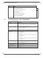
5.2
Power Specifications - Power Supply Module
Table 7: Power Supply Module Data
Attribute
Specification
Power Supplies
Dual redundant power supply slots
1 or 2 hot-swappable power supplies, according to configuration
Power supply with built-in power inlet
Electrical ratings [V, A, hz]
100-240Vac, 5.0A, 50/60 Hz
2.6A@120V 1.54A@230V
47-63Hz, auto-sensing
Power Inlet Type
C14
Power Rating
Power consumption*:
4036 - Maximum: 202W
Typical: 152W
(Numbers relate to copper cables. For optic cables add 1.5W per port.)
2036 - Maximum: 187W
Typical: 141W
(Numbers relate to copper cables. For optic cables add 1.5W per port.)
BTU/hour = Watts x 3.413
Each optical adapter in use adds 1.5W max to the above consumption.
Power Factor:
120 Vac/60 Hz/Max Load = 0.99
230 Vac/60 Hz/Max Load = 0.96
Maximum Power Draw
256W
Power Supply Efficiency
83%(115V) / 87%(230V)
Leakage current @ 254V
2.422 [mA]
2 power cords
2-meter long, with a universal plug for PDU (Power Distribution Unit)
25
Technical Specifications and Certifications
5.3
Certifications
Safety
cTUVus (USA/CAN); CE according to EN 60950-1 First Ed.
MET Labs (NRTL)
CE according to EN 69950-1
CSA C22.2 60950-1
S-Mark Argentina
CB Certificate and report, according to IEC 60950-1 First Ed.
MIC Korea
Gost-R
EMC Certifications
FCC Part 15, Subpart B, Class A and testing to ANSI 63.4
Industry Canada
ICES-003 (CAN/CSA-CEI/IEC CISPR 22:02)
CE EN55022: 1998 + A1:2000 + A2:2003
EN55024: 1998 + A1:2001 + A2:2003
EN 61000-3-2:00+A2(05) Harmonic current emissions
EN 61000-4-2: 1995 + A1: 98 + A2: 2001
EN 61000-4-3: 02 + A1: 2002
EN 61000-4-4: 1995 + A1: 01 +A2:2001
EN 61000-4-5: 1995 + A1: 2001
EN 61000-4-6: 1996 + A1: 2001
EN 61000-4-8: 1993 + A1:2000
EN 61000-4-11: 1994 + A1: 2001
EN 61000-3-3:94+A1 (01) Voltage fluctuations and flicker
Japan VCCI Technical Requirements, V.3/2001.04/CISPR 22:1997 + A1: 2000 + A2:
2002, Class A.
Australian/New Zealand C-Tick, AS/NZS CISPR 22:04
MIC Korea
Restricted Hazardous Substances Certification
RoHS-5
InfiniBand Certification
IBTA 1.2
26
Grid Director 4036/2036 Installation Manual
5.4
Gost-R Certification
The Mellanox products comply with the Gost-R Russian safety regulations.
5.5
Declarations
5.5.1
Declaration of Conformity
Mellanox products comply with the Radio & Telecommunications Terminal Equipment
Directive 99/5/EEC, the EMC Directive 89/336/EEC, and of the Low Voltage Directive
73/23/EEC.
5.5.2
Hazardous Substances (RoHS 5) Compliance Declaration
Mellanox products comply with the RoHS directive under the exemption (RoHS 5) of lead in
solders for servers, storage and telecommunication infrastructure.
27
Technical Specifications and Certifications
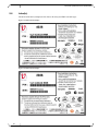
5.6
Label(s)
The 4036/2036 label (example) below shows all safety and EMC text and logos.
Figure 11: 4036 Label (Example)
Figure 12: 2036 Label (Example)
28
Grid Director 4036/2036 Installation Manual
5.7
Shock and Vibration
Prepare the 4036/2036 switch to ship in a rack by carefully following the rail kit installation
and instructions, as detailed in Chapter 6 (on page 31). The 4036/2036 is susceptible to shock
and vibration damage if the rail kit installation instructions are not followed precisely.
5.8
Chassis Clearance Requirements
Table 8: Clearance Requirements
5.9
Area
Recommended Minimum Clearance
Front of the rack
4" (10 cm)
Rear side of the rack
4" (10 cm)
Space below the chassis
No limits
Space on top of the chassis
No limits
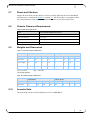
Weights and Dimensions
Table 9: Unpacked Weights & Dimensions
English (lbs/in)
Metric (kg/cm)
Module
Weight
D
W
H
Weight
D
W
H
4036/2036
17
15.7
17
1.7
7.7
40*
43*
4.3*
Power Supply
2.8
10.2
4.9
1.6
1.3
26
12.4
4
Fan
1.1
4.1
7.1
1.7
0.5
10.5
18
4.3
1 in = 2.54 cm
1 kg = 2.205 lbs
* Including handles
Table 10: Packed Weights & Dimensions
English (lbs/in)
5.10
Metric (kg/cm)
Module
Weight
D
W
H
Weight
D
W
H
4036/2036
31.31
24.41
22.44
6.69
14.2
62
57
17
Acoustic Data
The 2036/4036 acoustic noise Sound Pressure Level is: 64.3 dB (A)
29
Technical Specifications and Certifications
5.11
Export Information
CTP (Composite Theoretical Performance) is a calculation measured in MTOPS (millions of
theoretical operations per second).
The 460EX/460GT contain a 440H6 core (not a 460 core; it is called 460 to distinguish it as a
90 nm core).
The CTP (in MTOPS) for the PPC440 core = (17/18) * F
(where F is the CPU clock rate in MHz).
The following table provides CTP values.
5.12
CTP value for the PPC440 core
460EX/460GT @ 600MHz
~ 567 MTOPS
CTP value for the PPC440 core
460EX/460GT @ 1000MHz
~ 944 MTOPS
ECCN
5A991C
Shipping Restrictions
None.
Chapter 5
30
Grid Director 4036/2036 Installation Manual
6
Hardware Installation
This chapter describes how to prepare your site for installation and how to prepare and install
the 4036/2036 switch.
The 4036/2036 switch is a 19” rack mounted, 1U high chassis provided with a rail kit
accommodating racks of different depths with a front-to-back distance between mounting rails
of 26" to 36" (660 mm to 914 mm).
It is recommended to use the optional 4036/2036 Cabling Guide Brackets to arrange the
numerous cables that are connected to a chassis.
6.1
Installation Options
Option 1 – The front of the switch faces the front of the rack and is installed with a 5-in.
indentation. This allows AC inlets accessibility from the front of the rack while the power
cables are routed sideways to the power source. This option is detailed in Option 1 (on page
35).
Option 2 – The rear of the switch (InfiniBand connector side) faces the front of the rack and is
installed in-line with the rack’s front rails. This option is detailed in Option 2 (on page 42).
Option 3 – For the iDataplex rack - The rear of the switch (InfiniBand connector side) faces
the front of the iDataplex rack and is installed in-line with the rack’s front rails. This option is
detailed in Appendix A (on page 59).)
CAUTION: Before installing the 4036/2036 switch in a rack, read the Site Planning (on
page 32) section and Safety Information to get familiar with proper site and
environmental conditions.
6.1.1
Cooling
For both option 1 and option 2, the switch can support both front to rear and rear to front
cooling options, based on the specific part number that was ordered (different fan unit).
6.2
Required Tools
The following materials and tools are required for mounting the 4036/2036 chassis into a rack.
Table 11: Materials and Tools Required
Quantity
Description
1
Flat-blade screwdriver
1
Phillips screwdriver
1
Measuring tape
8
Floating clip nuts (not provided by Mellanox)
8
Phillips screws (not provided by Mellanox)
31
Hardware Installation
6.3
Site Planning
Planning the proper location and layout of your equipment rack or wiring closet is essential for
successful 4036/2036 switch operation. Equipment placed too close together or in an
inadequately ventilated area can cause overheating of the system. In addition, poor equipment
placement can render system panels inaccessible and difficult to maintain.
To ensure normal operation and avoid unnecessary maintenance, plan your site configuration
and prepare your site before installation.
6.3.1
Rack and Clearance Requirements
The 4036/2036 switch occupies 1U in a 19"rack and can be mounted either way, with the
InfiniBand ports facing the rear or the front of the rack. Switch cooling direction is either from
back-to-front or front-to-back, according to the switch fan unit configuration.
The rack brackets mounting holes conform to the IEA-310 standard for 19-inch racks.
The 4036/2036 switch places no restrictions on rack location. It is recommended to mount the
4036/2036 chassis near the middle of the rack, at or near eye level, to make it easy to see status
indicators, port numbers, etc.
It is also recommended to mount the rear side of the 4036/2036 switch in a way that enables
easy access to the InfiniBand cables, connectors, and LED indicators. It is recommended to
leave 4" (10 cm) for chassis clearance both in the front and the rear of the chassis. These
requirements are also listed in Chassis Clearance Requirements (on page 29).
6.3.2
Site Environment Specification
For the operating and non-operating environmental site requirements for the 4036/2036, see
Power Specifications - Power Supply Module (on page 25).
The system can continue to operate within specified environmental ranges; however, a
measurement that approaches the minimum or maximum of a range indicates a potential
problem. You can maintain normal operation by anticipating and correcting environmental
conditions before they exceed the maximum operating range.
6.3.3
Power Requirements
Power requirements are useful for planning the power distribution system needed to support
the 4036/2036 switch. Heat dissipation is an important consideration for sizing the
air-conditioning requirements for an installation. Verify the available power source at the site
for the type of device you are installing.
For the 4036/2036 switch power requirements, see Power Specifications - Power Supply
Module (on page 25).
The 4036/2036 switch requires one or two power connections using standard 3-wire AC power
cords including a safety ground. The input voltage characteristics can be found in the power
supply specifications, in Power Specifications - Power Supply Module (on page 25).
The 4036/2036 switch includes two hot-swappable redundant power supplies, providing full
back-up purposes.
32
Grid Director 4036/2036 Installation Manual
6.3.4
Site Preparation Checklist
To help prepare your site for installing the Grid Director 4036/2036 chassis, use the following
checklist.
Table 12: Site Preparation Checklist
Task
Prepared by
Date
Notes
Environmental requirements
Locate power sources
Measure space for the rack, including specified
maintenance clearances
Acquire specified cables and connectors
6.4
Measuring the Distance between Mounting Rails
To measure the distance between the rack mounting rails:
1. Place the 4036/2036 chassis on a flat surface.
2. Using a measuring tape, measure the front-to-back distance between the rack vertical
mounting rails. This step is very important so that you know exactly how to calculate the
exact rail length.
3. Mark the rack's U levels at which you would like to mount the switch. This is important so
that you can install the clip nuts in the adequate holes and ensure that the chassis is leveled.
4. Using a flat screwdriver, install the clip nuts in the rack at the U level noted in Step 3.
6.5
Assembling and Mounting the Rail
6.5.1
Rail Kit
The fixed rail is supplied as part of the rail kit and accommodates different rack depths.
The rail mounting has holes spaced 2 inches apart and can be mounted in several positions
along the side of the chassis to accommodate the depth of the rack.
Installation Option 1 (on page 35) and Option 2 (on page 42) require a rail kit.
Installation option 3 (see Appendix A (on page 59)) requires a mounting kit for the
iDataplex rack.
The following table shows the list of items required for the installation of the fixed rail. Note
that this only applies to Option 1 and 2. Option 3 (see Appendix A) entails different parts.
Note: Item sizes are not proportional
33
Hardware Installation
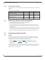
Table 13: Rail Kit (P/N KIT-00008) Detailed Part List
Item
P/N
2 x short bracket
290000169
2 x Mounting
Bar
MEC-0055
6
Illustration
Front side of the chassis
34
14 x Pan Head
Philips Screw,
8-32 x 1/4" with
tooth lock
washer and
nylon patch
FAS-0004
4
Long Bracket
(right side)
MEC-0055
5
Long Bracket
(left side)
MEC-0055
4
Rear side of the chassis
Grid Director 4036/2036 Installation Manual
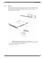
6.5.2
Option 1
The rail assembly described in this section enables front-to-rear switch installation within the
rack, meaning that the front of the switch faces the front of the rack. The front of the switch is
recessed 5 inches from the vertical rail of the rack to allow connecting the power cords from
the front side of the rack.
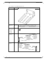
Figure 13: 4036/2036 – Option 1 Assembly
NOTE: Standard rack clip nuts and rack screws are not provided.
To mount the 4036/2036 in a rack using Option 1
1. Put the chassis on a flat surface.
35
Hardware Installation
Mount the long bracket at the front of the chassis using three 8-32x1/4" pan head Philips
screws.
Important: Left and right long brackets are different. Make sure that you are using the
correct bracket. The mounting ear at the end of the bracket should face out.
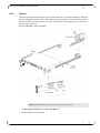
Figure 14: Mounting the long bracket
2. Position the mounting bar and adjust it according to the rack measurements you made while
Measuring the Distance between Mounting Rails (on page 33).
Note: Make sure that the distance is between 0.5" to 1" smaller than the distance you
measured between the two vertical rack rails.
Figure 15: Positioning and aligning the mounting bar and long bracket
Total distance = rack measurements you made in while Measuring the Distance between
Mounting Rails (on page 33).
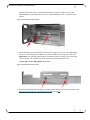
3. Connect the mounting bar to the side of the switch using two 8 32x1/4" pan head Philips
screws using the top holes of the mounting bar.
Make sure to install one screw at the center of the switch and the second one at the rear of
the switch.
Figure 16: Securing the mounting bar
Switch Rear
Switch Front
4. Repeat the previous steps (1-3) on the other side of the chassis.
36
Grid Director 4036/2036 Installation Manual
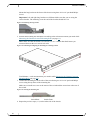
5. Ensure that the clip nuts are already installed in the rack holes of the correct U level (on all
four vertical rack rails) as described in Measuring the Distance between Mounting Rails
(on page 33).
Note: Rack clip nuts are not provided by Mellanox.
Figure 17: Installing the clip nuts and placing the power cord
6. Place the power cords with the female connector facing the front of the rack (or the switch)
with approximately 10" hanging out of the front.
Route the other side (male connector) of the power cord to the rear of the rack. Do not
connect it to the PDU at this stage.
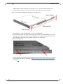
7. Lift and position the chassis, aligning the holes of all brackets with the rack holes of the
correct U level.
Gently push the switch inwards leaving it slightly protruded.
Figure 18: Inserting the switch into the rack
37
Hardware Installation
8. Place the power cords over the indentation of the long brackets.
Figure 19: Power cord over the long bracket
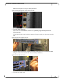
9. Secure each power cord with a cable tie wrap so that you can still adjust the length of the
cord if required.
Figure 20: Securing power cords
10.Connect the power cords to the switch power supplies (PSU).
Figure 21: Connecting the power cables
11.Push the switch inwards (from the front side of rack) until the long bracket comes together
with the rail.
38
Grid Director 4036/2036 Installation Manual
12.Fasten the long brackets to the rack’s vertical rails using two screws per bracket and tighten
them.
Figure 22: Secure the long brackets to the rack rail
13.Mount a short bracket from the inner side of the mounting bar and fasten it using two
8-32x1/4" pan head Philips screws.
At this stage, do not fully tighten the screws.
Important: Use the lower holes in the short bracket as shown in the figure.
Figure 23: Mounting the short bracket
39
Hardware Installation
14.Adjust the short brackets snuggly onto the rack’s vertical rail using the adjusting holes
(make sure that the rail is perfectly aligned by using the same U as used in the front of the
rack).
Figure 24: Adjusting the short bracket
15.Tighten the rack screws. (Rack screws are not supplied)
16.Tighten the short brackets to the mounting bars.
Figure 25: Securing Screws and Brackets
Result – Rack rear view
Figure 26: Switch mounted in a rack – Rack rear view
40
Grid Director 4036/2036 Installation Manual
Result – Rack front view
Figure 27: Switch mounted in a rack – Rack front view
41
Hardware Installation
6.5.3
Option 2
The rail assembly described in this section enables rear-to-front switch installation within the
rack, meaning that the rear of the switch (InfiniBand connector side) faces the front of the rack.
This rear-to-front chassis installation is in-line with the vertical front rails of the rack.
Figure 28: 4036/2036 – Option 2 Assembly
NOTE: Standard rack clip nuts and rack screws are not provided.
To mount the 4036/2036 in a rack using Option 2
1. Put the chassis on a flat surface.
42
Grid Director 4036/2036 Installation Manual
On each side of the chassis, mount the short brackets on the rear side of the switch
(InfiniBand port side) using three 8-32x1/4" pan head Philips screws, as shown on the
picture.
Figure 29: Mounting the short bracket
2. Mount the long bracket at the front of the chassis using two 8-32x1/4" pan head Philips
screws. Use the long bracket middle row orifices and the holes of top row on the rail.
Important: Left and right long brackets are different. Make sure that you are using the
correct bracket. The mounting ear at the end of the bracket should face out.
At this stage, do not fully tighten the screws.
Figure 30: Mounting the long bracket
3. Position the mounting bar and adjust it according to the rack measurements you made while
Measuring the Distance between Mounting Rails (on page 33).
43
Hardware Installation
Note: Make sure that the distance is between 0.5" to 1" greater than the distance you
measured between the two vertical rack rails to allow adjustment at a later stage.
Figure 31: Positioning and aligning the mounting bar and long bracket
Total distance = rack measurements + 0.5 to 1" for adjustment.
4. Secure the rail on the side of the switch using two 8-32x1/4" pan head Philips screws (use
the holes on the top row). Make sure you install one screw in the middle of the switch and
the other screw at the edge (use the holes on the top row of the rail).
Figure 32: Securing the rail
5. Ensure that the clip nuts are already installed in the rack holes of the correct U level (on all
four vertical rack rails) as described in Measuring the Distance between Mounting Rails
(on page 33).
44
Grid Director 4036/2036 Installation Manual
Note: Rack clip nuts are not provided by Mellanox.
Figure 33: Placing the clip nuts on the vertical rack rails
6. Go to the front of the rack.
Note: For ease of installation, at least two qualified people should perform the
following steps.
Lift and position the switch with the connectors facing towards you and insert it into the
rack.
Figure 34: Insert the switch into the rack
7. Align the short bracket holes with the rack holes of the correct U level and secure them
using two rack screws on each side (not provided by Mellanox).
Figure 35: Secure the rack screws
8. Go to the rear of the rack.
45
Hardware Installation
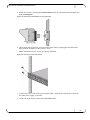
On each side, align the long bracket holes with the rack holes of the correct U level and
secure them using two rack screws (not provided by Mellanox) and two rail screws.
Figure 36: Installing the long bracket
9. Tighten the rack screws. (Rack screws are not supplied)
Figure 37: Securing the rack screws
10.Tighten the long brackets to the mounting bars.
46
Grid Director 4036/2036 Installation Manual
Important: This step should be done last.
Figure 38: Securing the long bracket screws to the mounting bar
Result – Rack front view
Figure 39: Switch mounted in a rack – Rack front view
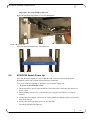
6.6
4036/2036 Switch Power Up
Once the 4036/2036 chassis is secure within the rack, electrical cables from the power
distribution source can be fitted in preparation for connection.
Two power cords are supplied by Mellanox, one per power supply unit.
To power up the 4036/2036 switch:
1. Ensure that all site power requirements have been met before connecting the chassis to a
power source.
2. Before turning on the power, verify that the power supplies and fan tray are properly
inserted.
3. Connect the power supply cords to the AC inlets of the Power Supplies (PSU) located at the
front of the chassis.
4. Connect the other side of the power cords to the PDU.
The PWR LED indicator lights up.
47
Hardware Installation
6.7
Field Replaceable Units
6.7.1
Fan Unit
The 4036/2036 switch has a hot swappable Fan Unit with three fans that are used to maintain
proper cooling, as shown.
In normal operation, the two fans work at 50% utilization.
In case of fan failure or high temperature detection, the fans go into Turbo mode. In case of fan
failure, the fan drawer LED and the PS/FAN LED on the rear panel blink.
When removing the fan unit, the system can continue to function up to 5 minutes before a new
fan unit is installed.
Figure 40: Replacing the Fan
To replace the hot-swappable Fan module
1. Release the captive fasteners at each side of the fan and gently remove it from its slot.
2. Position the rear of the new fan in the slot.
3. Holding the fan level, slide it into the slot until it meets resistance at the chassis connector.
It should slide smoothly and easily.
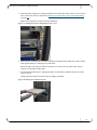
4. Push the module further until it is completely seated.
5. Use the captive fasteners at each side of the fan to secure it in place.
6.7.2
Power Supplies
The 4036/2036 switch has two identical hot swap Power Supplies in the side bays of the unit
chassis in order to maintain proper cooling, as shown.
The 4036/2036 switch supports current sharing operation of the two power supplies, if
applicable.
48
Grid Director 4036/2036 Installation Manual
When removing a power supply from the chassis, the other supply can power the entire
chassis.
Figure 41: Replacing the Power Supply
NOTE: Power supplies can be replaced while the power is ON. However, it is
recommended to turn the power OFF before replacing the power supply.
To replace a hot-swappable power supply module
1. Release the captive fasteners at each side of the power supply and gently remove the power
supply from its bay.
2. Position the rear of the new power supply in the bay.
3. Holding the power supply level, slide it into the slot until it meets resistance at the chassis
connector. It should slide smoothly and easily.
4. Push the module further until it is completely seated.
5. Use the captive fasteners at each side of the power supply to secure it in place.
Chapter 6
49
Cabling
7
Cabling
This chapter provides details on the 4036/2036 switch cable guide brackets installation and
cable management.
7.1
Cabling Guide Bracket Installation
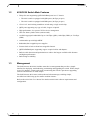
NOTES:
Selecting the optimal InfiniBand cable length depends on the overall cluster configuration and
requires proper planning to produce orderly and maintainable cabling.
The rack space for the 4036/2036 switch should be free from obstructions such as power strips.
The Cabling Guide brackets (CG-24) are optional; however, it is recommended to use the
Cabling Guide Brackets.
The rack mounted Cabling Guide Brackets (CG-24) should be installed in the back of the rack
itself, facing out.
Rack rails should be free of PDU and power inlets.
Figure 42: Cabling Guide Bracket (CG-24)
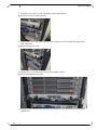
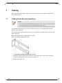
To Install the Cabling Guide Brackets (CG-24)
1. Install the Cabling Guide Bracket at the rear of the rack itself, on top or the rail bracket,
using two standard rack screws, as shown in Figure 7-2.
2. Repeat on the other side.
50
Grid Director 4036/2036 Installation Manual
3. Tighten the screws.
Figure 43: Installing a Cabling Guide Bracket
Figure 44: Installing a Cabling Guide Bracket (sliding rail)
51
Cabling
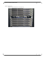
The following shows the final results.
Figure 45: Cable Management
Figure 46: Cabling
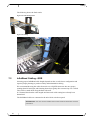
7.2
InfiniBand Cabling - QDR
Selecting proper InfiniBand cable lengths depends on the overall cluster configuration and
requires proper planning to produce orderly and maintainable cabling.
We recommend dressing the cables from each row of QSFP connectors into two groups
running them left and right, and fastening them down gently after connectivity was verified.
They will be routed down along the Rack side wall.
It is assumed here that the cable lengths and inter-rack cable routing have already been
determined.
The InfiniBand cables are connected to the 4036/2036 switch rear panel.
IMPORTANT: You can connect and disconnect cables while the 4036/2036 switch is
powered on.
52
Grid Director 4036/2036 Installation Manual
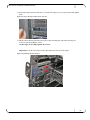
To connect an InfiniBand cable to a 4036/2036 switch
1. Insert the cable into the Cabling Guide bracket, if it applies.
2. Position the connector opposite a connector located on the rear of the 4036/2036 chassis.
Depending upon the InfiniBand connector type, squeeze the tabs on either side of the head
shell, and push the connector in place.
OR
Gently push the latch and push the connector in place.
3. Verify that the cable is inserted properly into the connector by gently tugging the cable;
verify that the Link State green-colored LED lights (and does not flash) indicating a good
physical connection.
4. Route the cable to the nearest convenient rack location and gently fasten in place with
Velcro tie or tie wraps.
CAUTION:
Avoid using tie wrap guns or similar tools; do not fasten the InfiniBand cable too tightly, as this
may cause irreversible damage to the cables.
Tie wraps and zip ties could cause potential damage to the cables. Velcro tie is the
recommended option.
Do not bend the InfiniBand cables too sharply. The minimum bend radius is 4" (10 cm).
InfiniBand Cabling — Do’s and Don’ts
Do not kink the cable
Do not over-bend the cable behind the connector
Do not twist the connector
For Port Cable Specifications, refer toAppendix A (on page 59).
7.3
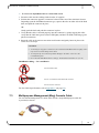
Multipurpose Management (Mng) Console Cable
For out-of-band management of a 4036/2036 switch, a single Multi-purpose cable kit
is provided, as shown.
53
Cabling
This kit contains the Mng cable and the following adaptors:
RJ45 to RJ45 cable
A RJ45 to DB-9 cross-adaptor for RS-232 console connection (CLI). (The DB-9 adaptor
has a number 26 printed on it. This means that pins 2 and 6 are crossed).
A RJ45 to DB-9 adaptor for RS-232 console connection
IMPORTANT: Both serial and Ethernet management ports of a 4036/2036 switch can
be connected simultaneously. However, the Ethernet ports of the front and the rear panels
cannot be connected simultaneously.
To connect multi-purpose cable of a 4036/2036 switch:
1. Connect the DB-9 connector and the RJ45 connector to each extremity of the multipurpose
console cable (Mng).
2. Connect the DB-9 connector to the 4036/2036 switch CLI port.
3. Connect the RJ45 connector to the Ethernet port either on the rear panel or on the front
panel (but not to both).
Chapter 7
54
Grid Director 4036/2036 Installation Manual
8
Operation
This chapter describes how to operate the 4036/2036 switch, once the installation is complete.
The 4036/2036 switch operation consists of making sure that it starts up properly and that any
initialization problems are resolved.
8.1
Powering on the 4036/2036 Switch
To start up the 4036/2036 unit:
The 4036/2036 chassis should be secured within the rack.
The InfiniBand cables should be plugged into the rear panel ports.
AC electrical circuit(s) should be available in preparation for connecting the 4036/2036 AC
cable(s).
CAUTION: Ensure that all site power requirements have been met before connecting the
chassis to the power source.
IMPORTANT: Line cords should be connected to separate AC circuits for maximum
fault tolerance in the event of power problems.
NOTE: For more details regarding the unit’s indicators, refer to 4036/2036 Switch LED
(on page 56).
Once the 4036/2036 chassis is secure within the rack, electrical cables from the power
distribution source can be fitted in preparation for connection.
Mellanox supplies two power cords, one per power supply unit.
To start up the 4036/2036 switch:
1. Ensure that all site power requirements have been met before connecting the chassis to a
power source.
2. Before turning on the power, verify that the power supplies and fan tray are properly
inserted.
3. At the rear of the 4036/2036 switch, plug the power cord into the power receptacle. Repeat
for the other power supply, if present.
4. Check that the power supply indicator light is green. Repeat for the other power supply, if
present.
5. Check for the following 4036/2036 switch status indicators:
PWR - Lights in green, indicating that the 4036/2036 switch is functional.
55
Operation
SM - Indicates the subnet management functionality: on for active mode, blinking for
standby mode.
PS/FAN - Lights solid green, indicating that the 4036/2036 switch is properly powered
and the fan unit is functioning adequately.
6. If any of these conditions is not met, refer to Solving Startup Problems (on page 58) to
isolate and, if possible, resolve the problem.
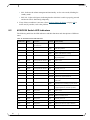
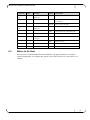
8.2
4036/2036 Switch LED Indicators
The following table lists the LED indicators and their functions and descriptions of different
states.
Table 14: 4036/2036 Switch LED Indications
LED Name
Color
Location
Status
Functionality
PWR
Green
Front panelOn each PSU
ON
PSU DC OK
OFF
PSU DC problem
ON
All fans operational, Nominal temperature
OFF
None of the fans are working
BLINK
At least one fan problem or
high temperature
ON
SM is active
OFF
SM is not active
BLINK
SM is in standby mode
ON
System power ok
OFF
System power problem
OFF
The device does not require attention
BLINK
The device requires attention
ON
All fans operational, Nominal temperature,
PSUs OK
OFF
All fans are not working or power down
BLINK
At least one fan problem or
high temperature, One PSU problem
ON
SM is active
OFF
SM is not active
BLINK
SM is in standby mode
ON
System power ok
OFF
System power problem
OFF
The device does not require attention
BLINK
The device requires attention
Fan
SM
Pwr
Info
Pwr/Fan
SM
Pwr
Info
56
Green
Green
Green
Green
Green
Green
Green
Green
Front panel (fan drawer)
Front panel (fan drawer)
Front panel (fan drawer)
Front panel (fan drawer)
Rear panel
Rear panel
Rear panel
Rear panel
Grid Director 4036/2036 Installation Manual
LED Name
Color
Location
Status
Functionality
IB physical
link
Green
Rear panel on each
QSFP port
ON
Port physical link is up
OFF
Port physical link is down or port is
disconnected
BLINK
Errors, Link is not stable
ON
Logical link is configured by SM
OFF
Logical link is not configured by SM
BLINK
traffic on the link
ON
Eth link is up
OFF
Eth link is down
OFF
No eth traffic
BLINK
Eth tragic activity
IB logical
link
Eth link
Amber
Green
Rear panel on each
QSFP port
Rear panel RJ45
connector
Amber
8.3
Where to Go Next
Once you have verified that the 4036/2036 hardware is properly installed, it is ready for
system configuration. To configure the system, refer to the Grid Director 4000 Family User
Manual.
Chapter 8
57
Troubleshooting
9
Troubleshooting
9.1
Overview
This chapter provides suggestions for solving startup problems and useful information when
contacting Mellanox Customer Service.
9.2
Solving Startup Problems
Try to solve startup problems using the 4036/2036 switch LED indicators.
Case 1
Problem with power supply – How do I know that my power supply is not functional?
Check the power cord and its connections. Check the installation of the power supply module.
If the indicator is blinking, the 4036/2036 power supply is faulty. Replace the power supply
module, if necessary.
NOTE: In single power supply systems, the AC power cord must be plugged into the
same side of the chassis as the power supply.
Case 2
What should I do when there is a Fan indication problem?
Replace the Fan Unit.
Case 3
When the physical link indicator is OFF, is the InfiniBand cable or connector faulty?
When the physical link indicator is ON, the logical link indicator is OFF, and the SM indicator
is ON, the InfiniBand cable or the connector is faulty. In case the InfiniBand cable is faulty,
replace the cable. If the problem is not solved, contact Mellanox Support.
9.3
Preparation before Contacting Customer Service
If you are unable to solve a startup problem after using the troubleshooting suggestions in this
chapter, contact a customer service representative for assistance and further instructions.
Before you call, have the following information ready to help your service representative
assist you as quickly as possible:
Date you received the Grid Director 4036/2036 switch
Chassis serial number (located on a label on the bottom of the chassis)
Type of software and release number
Maintenance agreement or warranty information
Brief description of the problem
Brief explanation of the steps you have already taken to isolate and solve the problem.
Appendix A
58
Grid Director 4036/2036 Installation Manual
Appendix A:
A.1
Option 3 – Chassis Installation
in an iDataPlex Rack
Unpacking the 4036/2036 Switch
NOTE: Keep the original packing materials; they will be needed if:
The product needs to be moved. For example if it is staged at one location before being
delivered at the production site.
A module needs to be returned for repair, replacement, or upgrade.
The 4036/2036 chassis is supplied in a box similar to the one shown in the following figure.
To unpack the 4036/2036 chassis, perform the following steps:
1. Open the box and check that they contain the items listed in the Packing List.
Figure 47: 4036/2036 Cardboard Package (Open) - Standard
2. Remove the box containing the Rail Kit, the Power Cords, and the multipurpose console
cable kit (Mng).
3. Remove the Getting Started Guide which also contains the documentation and software
CD.
4. Remove the top foam.
5. Carefully remove the 4036/2036 switch, lifting the it using the dedicated niche as shown in
Figure 2-2.
59
Troubleshooting
6. Remove the protective antistatic bag from the 4036/2036 switch.
A.1.1
Multipurpose Console Cable Kit
Refer to Multipurpose (Mng) Console Cable Kit (on page 53).
A.1.2
Packing the Switch
Refer to Packing the 4036/2036 Switch (on page 14).
A.2
Mounting the iDataplex Kit
The 4036/2036 switch is a 19" rack mounted, 1U high chassis provided with a rail kit
accommodating iDataplex racks with a front-to-back distance between mounting rails of
15.75" (400 mm). The switch cooling direction is from rear to front.
The following table lists the items required for the 4036/2036 installation in an Datplex rack.
NOTE: Item sizes are not proportional
Table 15: iDataplex Mounting Kit (P/N KIT-00004) Part List
60
Item
P/N
Quantity
19" MOUNT BRACKET
MEC-00409
x2
MOUNT HOLDER
MEC-00410
x2
MOUNT PLATE
MEC-00413
x2
14 x Pan Head Philips Screw,
8-32 x 1/4" with tooth lock
washer and nylon patch
FAS-00044
x8
Illustration
Grid Director 4036/2036 Installation Manual
Assembly in an iDataPlex Rack
Figure 48: 4036/2036 – Assembly in an iDataplex Rack
NOTE: Standard rack clip nuts and rack screws are not provided.
To mount the 4036/2036 in an iDataplex rack
1. Put the chassis on a flat surface.
2. On each side of the switch, attach the mount brackets to the rear of the chassis (connector
side) using two 8-32x1/4" pan head Philips screws.
Figure 49: Attaching the mount bracket
3. On each side of the switch, connect the mount holders on the front side of the switch
using two 8-32x1/4" pan head Philips screws.
61
Troubleshooting
Important: Make sure that you install the mount holders with the hook facing out, as
shown below.
4. Go to the rear of the rack:
1. Place two clip nuts on each side of the desired U level of the rack rails.
2. Secure the mount plates at the rear side of the rack rail (into the clip nuts) using two
screws.
Note: Rack clip nuts and screws are not provided by Mellanox.
Figure 50: Securing clip nuts and the mount plates onto the rack
62
Grid Director 4036/2036 Installation Manual
5. Install the switch by inserting the mount holders hooks into the dedicated rectangular slot
in the mount plates.
Figure 51: Inserting the mount holder into the mount plate
6. On the front side of the rack, secure the front of the chassis, aligning the mount brackets
holes with the rack holes of the correct U level.
Note: The Philips screws are not provided by Mellanox.
Figure 52: Securing the front of the chassis
7. Connect the power cords to the power supplie (PSU) at the front of the chassis (repeat for
the other power supply, if present).
8. At the rear of the chassis, connect the InfiniBand cables.
Appendix B
63
Troubleshooting
Appendix B:
Cabling Information
This appendix provides cabling and port pinout information for the 4036/2036 switch.
B.1
IB Port Cable Specifications
The following table describes cabling specifications for the 4036/2036 4X InfiniBand ports.
Table 16: 4X InfiniBand Port Cabling Specifications
Type
4XQDR
4XQDR – 4036/HCA
4X DDR 2036/ISR2012
64
Maximum Cable Length
AWG
Length (ft.)
Length (m)
Gore Cable P/N
26
16.4
7
QSN7600-5
26
13.1
4
QSN7600-4
28
9.84
3
QSN3800-3
30
6.57
2
QSN3300-2
30
4.93
1.5
QSN3300-1.5
30
3.28
1
QSN3300-1
30
1.64
0.5
QSN3300-0.5
26
19.7
8
QSN7600-6
26
16.4
5
QSN7600-5
28
9.84
3
QSN3800-3
30
6.56
2
QSN3300-2
24
32.8
10
QSIBN-5000-10
24
26.3
8
QSIBN-5000-8
26
23.02
7
QSIBN-5600-7
28
19.7
6
QSIBN-5800-6
30
16.4
5
QSIBN-5300-5
30
13.1
4
QSIBN-5300-4
Grid Director 4036/2036 Installation Manual
B.2
1 GbE Ports (Management)
Use modular, RJ-45, straight-through UTP cables to connect the 10/100/1000 Fast Ethernet
ports to external switches and routers. Use modular, RJ-45 cross-connect cables to connect to
end systems. The following figures show straight-through cables and cross-connect cables.
Figure 53: Straight-through Cables
Figure 54: Cross-connect Cables
The 10/100/1000 Fast Ethernet port supports a RJ-45 connector.
Appendix C
65
Troubleshooting
Appendix C:
QSFP Cable
QSFP (Quad Small Form-factor Pluggable) Key Features:
Small size, high density, hot-pluggable connector with four transmit and four receive
channels
Supports both types of cables:
Copper active or passive cable.
Copper passive cable is equipped with two simple passive connectors and a standard
copper cable.
Copper active cable equipped with an active device to optimize signal quality.
Fibre optic cable delivered as either:
Fibre cable with two separate modules
Active optic cable where cable and optic adaptors are delivered as a single unit
(permanently attached cable)
Data rate: 2.5 Gbps (SDR), 5 Gbps (DDR), and up to 10 Gbps (QDR) per channel
QSFP optic modules use standard MPO parallel 12-fibre jacketed ribbon optical connector
Provide manageability, discovery, and identification capability, such as vendor
identification, module part number, serial number, cable type, using low-speed two-wire
(I2C) interface
Active cables: Integrates digital diagnostic capability to monitor link performance
Latching mechanism
Mechanical Dimensions, as shown:
Figure 55: QSFP Connector-Dimensions
NOTE: QSFP to CX4 cables are available to connect 4036/2036 equipped with QSFP
with legacy DDR/SDR systems equipped with CX4 connectors.
Overview
Each of the 4036/2036 ports on the switch is equipped with a transmit and receive circuit that
can adjust to fit different types of link characteristics and either optical or copper cables.
The QSFP cables, shown previously, transmit and receive up to 10 Gbps per channel (total:
up to 40 Gbps per port) over a single active/passive optical or copper cable, Passive copper
cables do not consume any additional power while active copper and optic cables consume up
to 1.5 Watt.
66
Grid Director 4036/2036 Installation Manual
The following figure shows the QSFP module with Copper or Optical cables. You can install
any combination of the three cable types in any of the 36 QSFP cages.
Figure 56: QSFP Connector
67