1
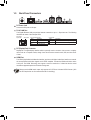
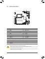
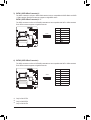
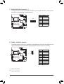
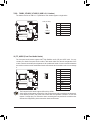
GA-H77TN GA-B75TN GA-H61TN User's Manual Rev. 1101 Motherboard GA-H77TN Jan. 31, 2013 GA-H77TN Motherboard Jan. 31, 2013 Motherboard GA-B75TN Jan. 31, 2013 GA-B75TN Motherboard Jan. 31, 2013 Motherboard GA-H61TN Feb. 08, 2013 GA-H61TN Motherboard Feb. 08, 2013 Copyright © 2013 GIGA-BYTE TECHNOLOGY CO., LTD. All rights reserved. The trademarks mentioned in this manual are legally registered to their respective owners. Disclaimer Information in this manual is protected by copyright laws and is the property of GIGABYTE. Changes to the specifications and features in this manual may be made by GIGABYTE without prior notice. No part of this manual may be reproduced, copied, translated, transmitted, or published in any form or by any means without GIGABYTE's prior written permission. Documentation Classifications In order to assist in the use of this product, GIGABYTE provides the following types of documentations: For detailed product information, carefully read the User's Manual. For product-related information, check on our website at: http://www.gigabyte.com Table of Contents Box Contents....................................................................................................................7 GA-H77TN/GA-B75TN/GA-H61TN Motherboard Layout.................................................8 Chapter 1 Hardware Installation......................................................................................9 1-1 1-2 1-3 1-4 1-5 1-6 Installation Precautions..................................................................................... 9 Product Specifications..................................................................................... 10 Installing the CPU and CPU Cooler................................................................ 13 Installing the Memory/Expansion Card........................................................... 13 Back Panel Connectors................................................................................... 14 Internal Connectors......................................................................................... 16 Chapter 2 BIOS Setup...................................................................................................28 2-1 2-2 The Main Menu............................................................................................... 30 Advanced Menu.............................................................................................. 32 2-2-1 2-2-2 2-2-3 2-2-4 2-2-5 2-2-6 2-2-7 2-2-8 2-2-9 2-3 2-4 2-5 2-6 ACPI Settings..........................................................................................................33 CPU Configuration...................................................................................................34 SATA Configuration.................................................................................................36 Intel (R) Rapid Start Technology..............................................................................37 H/W Monitor.............................................................................................................38 Intel(R) Smart Connect Technology.........................................................................39 Network Stack.........................................................................................................40 CPU PPM Configuration..........................................................................................41 Realtek PCIe GBE Family Controller.......................................................................42 Chipset Menu.................................................................................................. 43 Boot Menu....................................................................................................... 44 Security Menu................................................................................................. 47 Exit Menu........................................................................................................ 49 -6- Box Contents ;; GA-H77TN or GA-B75TN or GA-H61TN motherboard ;; Motherboard driver disk ;; User's Manual ;; One SATA power cable ;; I/O Shield ;; Screws kit for expansion cards • The box contents above are for reference only and the actual items shall depend on the product package you obtain. -7- GA-H77TN/GA-B75TN/GA-H61TN Motherboard Layout PCIEX4 F_USB2_3 F_USB2_2 DMIC_CON CODEC iTE Super I/O BIOS Socket 1155 FUSB2_1 BATTERY SO_DIMM2 SYS_FAN SATA0 SYS_PANEL CPU_FAN MM Only for GA-H77TN. NN Only for GA-B75TN. OO Only for GA-H61TN. -8- SATA1 SATA3jk SATA2 Realtek GbE LAN MPCIE1X LCD_VCC BL_SW WF_LED LVDS MON_SW LINE_OUT USBX_2 USBX_1 DP SO_DIMM1 SATA_PWR MIC_IN HDMI Intel® H77j/ B75k/H61l FPD_PWR DISPLAY_BRT FP_AUDIO SPKR EXT_CON LAN CLR_CMOS FUSB2_5 ATX_19V DC_IN Chapter 1 Hardware Installation 1-1 Installation Precautions The motherboard contains numerous delicate electronic circuits and components which can become damaged as a result of electrostatic discharge (ESD). Prior to installation, carefully read the user's manual and follow these procedures: •• Prior to installation, make sure the chassis is suitable for the motherboard. •• Prior to installation, do not remove or break motherboard S/N (Serial Number) sticker or warranty sticker provided by your dealer. These stickers are required for warranty validation. •• Always remove the AC power by unplugging the power cord from the power outlet before installing or removing the motherboard or other hardware components. •• When connecting hardware components to the internal connectors on the motherboard, make sure they are connected tightly and securely. •• When handling the motherboard, avoid touching any metal leads or connectors. •• It is best to wear an electrostatic discharge (ESD) wrist strap when handling electronic components such as a motherboard, CPU or memory. If you do not have an ESD wrist strap, keep your hands dry and first touch a metal object to eliminate static electricity. •• Prior to installing the motherboard, please have it on top of an antistatic pad or within an electrostatic shielding container. •• Before unplugging the power supply cable from the motherboard, make sure the power supply has been turned off. •• Before turning on the power, make sure the power supply voltage has been set according to the local voltage standard. •• Before using the product, please verify that all cables and power connectors of your hardware components are connected. •• To prevent damage to the motherboard, do not allow screws to come in contact with the motherboard circuit or its components. •• Make sure there are no leftover screws or metal components placed on the motherboard or within the computer casing. •• Do not place the computer system on an uneven surface. •• Do not place the computer system in a high-temperature environment. •• Turning on the computer power during the installation process can lead to damage to system components as well as physical harm to the user. •• If you are uncertain about any installation steps or have a problem related to the use of the product, please consult a certified computer technician. -9- 1-2 Product Specifications CPU Support for Intel® Core™ i7 processors/Intel® Core™ i5 processors/ Intel® Core™ i3 processors/Intel® Pentium® processors/Intel® Celeron® processors in the LGA1155 package (Supports up to 77W) (Go to GIGABYTE's website for the latest CPU support list.) L3 cache varies with CPU Chipset Intel® H77 j/B75 k/H61 l Express Chipset Memory 2 x 1.5V DDR3 SO-DIMM sockets supporting up to 8 GB of system memory *Due to a Windows 32-bit operating system limitation, when more than 4 GB of physical memory is installed, the actual memory size displayed will be less than the size of the physical memory installed. Dual channel memory architecture Support for DDR3 1600/1333/1066/800 MHz memory modules (Go to GIGABYTE's website for the latest supported memory speeds and memory modules.) Onboard Graphics Integrated Graphics Processor: -1 x HDMI 1.3 port, supporting a maximum resolution of 1920x1200 -1 x DisplayPort, supporting a maximum resolution of 2560x1600 - 1 x LVDS connector Audio Realtek® ALC887 codec High Definition Audio 2/4/5.1/7.1-channel * T o configure 5.1/7.1-channel audio, you have to use an HD front panel audio module and enable the multi-channel audio feature through the audio driver. LAN 1 x Realtek® GbE LAN chip (10/100/1000 Mbit) Expansion Slots 1 x PCI Express x4 slot (Supports 25W only) (The PCIEX4 slot conforms to PCI Express 3.0 standard.) 1 x Mini PCI Express x1 slot Chipset: GA-H77TN: - 2 x SATA 6Gb/s connectors (SATA0/1) supporting up to 2 SATA 6Gb/s devices - 2 x SATA 3Gb/s connectors (SATA2/3) supporting up to 2 SATA 3Gb/s devices - 1 x mSATA connector -Support for RAID 0, RAID 1, RAID 5, and RAID 10 GA-B75TN: - 1 x SATA 6Gb/s connector (SATA0) supporting up to 1 SATA 6Gb/s device - 3 x SATA 3Gb/s connectors (SATA1/2/3) supporting up to 3 SATA 3Gb/s devices - 1 x mSATA connector GA-H61TN: - 3 x SATA 3Gb/s connectors (SATA0/1/2) supporting up to 3 SATA 3Gb/s devices - 1 x mSATA connector Storage Interface MM Only for GA-H77TN. NN Only for GA-B75TN. OO Only for GA-H61TN. - 10 - USB Internal Connectors Back Panel Connectors I/O Controller Chipset: GA-H77TN/GA-B75TN: -Up to 4 USB 3.0/2.0 ports on the back panel -Up to 5 USB 2.0/1.1 ports available through the internal USB headers (Card reader/Touch panel/webcam and other devices) GA-H61TN: -Up to 9 USB 2.0/1.1 (4 ports on the back panel,5 ports available through the internal USB headers) (Card reader/Touch panel/webcam and other devices) 1 x 2-pin power connector 1 x CPU fan header 1 x system fan header 2 x SATA 6Gb/s connectors j 2 x SATA 3Gb/s connectors j 1 x SATA 6Gb/s connector k 3 x SATA 3Gb/s connectors k 3 x SATA 3Gb/s connectors l 1 x mSATA connector 1 x SATA power connector 4 x USB 2.0/1.1 headers 1 x front panel header 1 x front panel audio header 1 x digital microphone header 1 x AIO speaker header 1 x LVDS connector 1 x LVDS drive voltage header 1 x flat panel display power header (both panel and backlight inverter) 1 x flat panel display power connector 1 x backlight switch header 1 x flat panel display switch header 1 x WIFI activity indicator LED header 1 x Clear CMOS jumper 1 x HDMI port 1 x DisplayPort 4 x USB 3.0/2.0 ports jk 4 x USB 2.0/1.1 ports1 x RJ-45 port l 2 x audio jacks (Line Out, Mic In) 1 x DC-In power connector iTE® I/O Controller Chip MM Only for GA-H77TN. NN Only for GA-B75TN. OO Only for GA-H61TN. - 11 - Hardware Monitor System voltage detection CPU/System temperature detection CPU/System fan speed detection CPU fan speed control BIOS *For 4-pin CPU coolers only. *Whether the CPU fan speed control function is supported will depend on the CPU cooler you install. 1 x 64 Mbit flash Use of licensed AMI EFI BIOS PnP 1.0a, DMI 2.0, SM BIOS 2.6, ACPI 2.0a Operating System Support for Windows 8/7/XP Form Factor Thin Mini-ITX Form Factor; 17.0cm x 17.0cm * GIGABYTE reserves the right to make any changes to the product specifications and product-related information without prior notice. - 12 - 1-3 Installing the CPU and CPU Cooler Read the following guidelines before you begin to install the CPU/CPU cooler: •• Make sure that the motherboard supports the CPU. (Go to GIGABYTE's website for the latest CPU support list.) •• Always turn off the computer and unplug the power cord from the power outlet before installing the CPU to prevent hardware damage. •• Locate the pin one of the CPU. The CPU cannot be inserted if oriented incorrectly. (Or you may locate the notches on both sides of the CPU and alignment keys on the CPU socket.) •• Apply an even and thin layer of thermal grease on the surface of the CPU. •• Do not turn on the computer if the CPU cooler is not installed, otherwise overheating and damage of the CPU may occur. •• Set the CPU host frequency in accordance with the CPU specifications. It is not recommended that the system bus frequency be set beyond hardware specifications since it does not meet the standard requirements for the peripherals. If you wish to set the frequency beyond the standard specifications, please do so according to your hardware specifications including the CPU, graphics card, memory, hard drive, etc. •• For installing the CPU cooler, please refer to chassis user's manual. 1-4 Installing the Memory/Expansion Card Read the following guidelines before you begin to install the memory: •• Make sure that the motherboard supports the memory. It is recommended that memory of the same capacity, brand, speed, and chips be used. (Go to GIGABYTE's website for the latest supported memory speeds and memory modules.) •• Make sure the motherboard supports the expansion card. Carefully read the manual that came with your expansion card. •• Always turn off the computer and unplug the power cord from the power outlet before installing the memory/expansion card to prevent hardware damage. •• Memory modules have a foolproof design. A memory module can be installed in only one direction. If you are unable to insert the memory, switch the direction. - 13 - 1-5 Back Panel Connectors DC Power Jack Connect the DC power to this port. RJ-45 LAN Port The Gigabit Ethernet LAN port provides Internet connection at up to 1 Gbps data rate. The following describes the states of the LAN port LEDs. Connection/ Speed LED Activity LED LAN Port Connection/Speed LED: State Orange Green Off Activity LED: Description 1 Gbps data rate 100 Mbps data rate 10 Mbps data rate State Blinking Off Description Data transmission or receiving is occurring No data transmission or receiving is occurring DP (DisplayPort) Connector DisplayPort is a digital display interface which is primarily used to connect a video source to a display device such as a computer monitor, though it can also be used to transmit audio, USB, and other forms of data. HDMI Port The HDMI (High-Definition Multimedia Interface) provides an all-digital audio/video interface to transmit the uncompressed audio/video signals and is HDCP compliant. Connect the HDMI audio/video device to this port. The HDMI Technology can support a maximum resolution of 1920x1200 but the actual resolutions supported depend on the monitor being used. Please note the HDMI audio output only supports AC3, DTS and 2-channel-LPCM formats. (AC3 and DTS require the use of an external decoder for decoding.) - 14 - USB 3.0 Ports jk The USB port supports the USB 3.0 specification. Use this port for USB devices such as a USB keyboard/mouse, USB printer, USB flash drive and etc. USB 2.0 Ports l The USB port supports the USB 2.0 specification. Use this port for USB devices such as a USB keyboard/mouse, USB printer, USB flash drive and etc. Line Out (Front Speaker Out/Green) The default Line Out (Front Speaker Out) jack. Stereo speakers, earphone or front surroundspeakers can be connected to Line Out (Front Speaker Out) jack. MIC In (Pink) The default MIC In jack. Microphone cab be connected to MIC In jack. • When removing the cable connected to a back panel connector, first remove the cable from your device and then remove it from the motherboard. • When removing the cable, pull it straight out from the connector. Do not rock it side to side to prevent an electrical short inside the cable connector. MM Only for GA-H77TN. NN Only for GA-B75TN. OO Only for GA-H61TN. - 15 - 1-6 Internal Connectors 4 15 10 7 19 8 20 24 6 18 11 22 12 23 17 5 21 1 13 25 2 14 3 4 9 16 1) SYS_PANEL 14) SYS_FAN 2) SATA0 15) DMIC_CON 3) SATA1 16) ATX_19V 4) SATA2 17) MON_SW 5) SATA3 18) BL_SW 6) FUSB2_1 19) SPKR 7) FUSB2_2 20) BATTERY 8) FUSB2_3 21) CLR_CMOS 9) FUSB2_5 22) LCD_VCC 10) FP_AUDIO 23) FPD_PWR 11) DISPLAY_BRT 24) WF_LED 12) LVDS 25) SATA_PWR 13) CPU_FAN Read the following guidelines before connecting external devices: • First make sure your devices are compliant with the connectors you wish to connect. • Before installing the devices, be sure to turn off the devices and your computer. Unplug the power cord from the power outlet to prevent damage to the devices. • After installing the device and before turning on the computer, make sure the device cable has been securely attached to the connector on the motherboard. - 16 - 1) F_PANEL (Front Panel Header) Connect the power switch, reset switch, speaker, chassis intrusion switch/sensor and system status indicator on the chassis to this header according to the pin assignments below. Note the positive and negative pins before connecting the cables. Pin No. 1 2 3 4 5 6 7 8 9 9 1 10 2 Signal Name HD+ MPD+ HD- MPD- GND PW+ RST PW- WF_LED Definition Hard Disk LED Signal anode (+) Power LED Signal anode (+) Hard Disk LED Signal cathode(-) Power LED Signal cathode(-) Ground Power Button anode (+) Reset Button Power Button cathode(-) Wifi active LED Signal The front panel design may differ by chassis. A front panel module mainly consists of power switch, reset switch, power LED, hard drive activity LED, speaker and etc. When connecting your chassis front panel module to this header, make sure the wire assignments and the pin assignments are matched correctly. DEBUG PORT 2) SATA0 (SATA 6Gb/s Connector)jk The SATA connectors conform to SATA 6Gb/s standard and are compatible with SATA 3Gb/s and SATA 1.5Gb/s standard. Each SATA connector supports a single SATA device. SATA0 (SATA 3Gb/s Connector)l The SATA connectors conform to SATA 3Gb/s standard and are compatible with SATA 1.5Gb/s standard. Each SATA connector supports a single SATA device. SATA0 1 7 MM Only for GA-H77TN. NN Only for GA-B75TN. OO Only for GA-H61TN. - 17 - Pin No. 1 2 3 4 5 6 7 Definition GND TXP TXN GND RXN RXP GND DEBUG PORT 3) SATA1 (SATA 6Gb/s Connector)j The SATA connectors conform to SATA 6Gb/s standard and are compatible with SATA 3Gb/s and SATA 1.5Gb/s standard. Each SATA connector supports a single SATA device. SATA1 (SATA 3Gb/s Connector)kl The SATA connectors conform to SATA 3Gb/s standard and are compatible with SATA 1.5Gb/s standard. Each SATA connector supports a single SATA device. SATA1 1 7 Pin No. 1 2 3 4 5 6 7 Definition GND TXP TXN GND RXN RXP GND DEBUG PORT 4) SATA2 (SATA 3Gb/s Connector) The SATA connectors conform to SATA 3Gb/s standard and are compatible with SATA 1.5Gb/s standard. Each SATA connector supports a single SATA device. SATA2 1 7 MM Only for GA-H77TN. NN Only for GA-B75TN. OO Only for GA-H61TN. - 18 - Pin No. 1 2 3 4 5 6 7 Definition GND TXP TXN GND RXN RXP GND DEBUG PORT 5) SATA3 (SATA 3Gb/s Connector)jk The SATA connectors conform to SATA 3Gb/s standard and are compatible with SATA 1.5Gb/s standard. Each SATA connector supports a single SATA device. SATA3 1 7 Pin No. 1 2 3 4 5 6 7 Definition GND TXP TXN GND RXN RXP GND 6) FUSB2_1 (USB 2.0/1.1 Header) The headers conform to USB 2.0/1.1 specification. Each USB header can provide two USB ports via an optional USB bracket. For purchasing the optional USB bracket, please contact the local dealer. 1 2 9 10 MM Only for GA-H77TN. NN Only for GA-B75TN. - 19 - Pin No. 1 2 3 4 5 6 7 8 9 10 Definition VCC VCC USB3USB2USB3+ USB2+ GND GND No Pin NC 7/8/9) FUSB2_2/FUSB2_3/FUSB2_5 (USB 2.0/1.1 Headers) The headers conform to USB 2.0/1.1 specification. Each header supports a single device. FUSB2_2/FUSB2_3 5 1 FUSB2_5 1 5 Pin No. 1 2 3 4 5 Definition VCC USBUSB+ GND No Pin 10) FP_AUDIO (Front Panel Audio Header) The front panel audio header supports Intel® High Definition audio (HD) and AC'97 audio. You may connect your chassis front panel audio module to this header. Make sure the wire assignments of the module connector match the pin assignments of the motherboard header. Incorrect connection between the module connector and the motherboard header will make the device unable to work or even damage it. 10 9 2 1 Pin No. 1 2 3 4 5 6 7 8 9 10 Definition F_MIC_L GND F_MIC_R GPIO_DET F_LINE_R F_MIC_JD GND No Pin F_LINE_L F_LINE_JD • The front panel audio header supports HD audio by default. • Audio signals will be present on both of the front and back panel audio connections simultaneously. • Some chassis provide a front panel audio module that has separated connectors on each wire instead of a single plug. For information about connecting the front panel audio module that has different wire assignments, please contact the chassis manufacturer. - 20 - 11) DISPLAY_BRT (Flat Panel Display Headers) The FPD is a high-speed interface connecting the output of a video controller in a laptop computer, computer monitor or LCD television set to the display panel. Most laptops, LCD computer monitors and LCD TVs use this interface internally. The headers conform to FPD specification. 8 1 Pin No. 1 2 3 4 5 6 7 8 Definition BKLT_EN BKLT_PWM BKLT_PWR BKLT_PWR BKLT_GND/Brightness_GND BKLT_GND/Brightness_GND Brightness_Up Brightness_Down 12) LVDS (LVDS Header) LVDS stands for Low-voltage differential signaling, which uses high-speed analog circuit techniques to provide multigigabit data transfers on copper interconnects and is a generic interface standard for high-speed data transmission. 1 40 Pin No. 1 2 3 4 5 6 7 8 9 10 11 12 13 14 15 16 17 18 19 20 - 21 - Definition ODD_Lane3_P ODD_Lane3_N ODD_Lane2_P ODD_Lane2_N ODD_Lane1_P ODD_Lane1_N ODD_Lane0_P ODD_Lane0_N EVEN_Lane3_P EVEN_Lane3_N EVEN_Lane2_P EVEN_Lane2_N EVEN_Lane1_P EVEN_Lane1_N EVEN_Lane0_P EVEN_Lane0_N EDID_GND LCD_VCC LCD_VCC LCD_VCC Pin No. 21 22 23 24 25 26 27 28 29 30 31 32 33 34 35 36 37 38 39 40 Definition NC EDID_3.3V LCD_GND LCD_GND LCD_GND ODD_CLK_P ODD_CLK_N BLKT_GND BLKT_GND BLKT_GND EDID_CLK BLKT_ENABLE BLKT_PWM_DIM EVEN_CLK_P EVEN_CLK_N BLKT_PWR BLKT_PWR BLKT_PWR NC EDID_DATA 13/14) CPU_FAN/SYS_FAN (Fan Headers) All fan headers on this motherboard are 4-pin. Most fan headers possess a foolproof insertion design. When connecting a fan cable, be sure to connect it in the correct orientation (the black connector wire is the ground wire). The speed control function requires the use of a fan with fan speed control design. For optimum heat dissipation, it is recommended that a system fan be installed inside the chassis. 1 CPU_FAN Pin No. 1 2 3 4 Definition GND +12V Sense Speed Control SYS_FAN • Be sure to connect fan cables to the fan headers to prevent your CPU and system from overheating. Overheating may result in damage to the CPU or the system may hang. • These fan headers are not configuration jumper blocks. Do not place a jumper cap on the headers. 15) DMIC_CON (Digital Microphone Header) This header is for a digital microphone. 1 5 - 22 - Pin No. 1 2 3 4 5 Definition Power DMI DATA GND DMI CLK No Pin 16) ATX_19V (2 Pin Power Connector) This power connector is for the integrated 19V chassis power supply. 2 1 Pin No. 1 2 Definition GND +19V 17) MON_SW (Flat panel display switch header) This header allows you to connect an on/off switch for the display. 1 - 23 - Pin No. 1 2 Definition Mon_SW GND 18) BL_SW (Back Light Switch) The Back Light switch provides the function for screen back light adjustment. 1 Pin No. 1 2 Definition BL_DOWN BL_UP 19) SPKR (Speaker Header) This header connects to the speaker on the chassis front panel. The system reports system startup status by issuing a beep code. One single short beep will be heard if no problem is detected at system startup. 4 1 - 24 - Pin No. 1 2 3 4 Definition Speaker OUT LSpeaker OUT L+ Speaker OUT R+ Speaker OUT R- 20) BATTERY (Battery cable connector) The battery provides power to keep the values (such as BIOS configurations, date, and time information) in the CMOS when the computer is turned off. Replace the battery when the battery voltage drops to a low level, or the CMOS values may not be accurate or may be lost. 2 1 Pin No. 1 2 Definition RTC Reset GND • Always turn off your computer and unplug the power cord before replacing the battery. • Replace the battery with an equivalent one. Danger of explosion if the battery is replaced with an incorrect model. • Contact the place of purchase or local dealer if you are not able to replace the battery by yourself or uncertain about the battery model. • Used batteries must be handled in accordance with local environmental regulations. 21) CLR_CMOS (Clearing CMOS Jumper) Use this jumper to clear the CMOS values (e.g. date information and BIOS configurations) and reset the CMOS values to factory defaults. To clear the CMOS values, use a metal object like a screwdriver to touch the two pins for a few seconds. Open: Normal operation (Default setting) Close: Clear CMOS data Always turn off your computer and unplug the power cord from the power outlet before clearing the CMOS values. •• After system restart, go to BIOS Setup to load factory defaults (select Load Optimized Defaults) or manually configure the BIOS settings (refer to Chapter 2, "BIOS Setup," for BIOS configurations). • - 25 - 22) LCD_VCC (LVDS drive voltage Jumper) This jumper can be used to provide different screen voltage settings. 1 1 1-2 Close: Set to 3V 2-3 Close: Set to 5V (Default setting) 23) FPD_PWR (Flat panel display power Jumper) This jumper allows you to select the required operating voltage for the backlight panel. 1 1 - 26 - 1-2 Close: Set to 12V 2-3 Close: Set to 19V (Default setting) 24) WF_LED (WIFI activity indicator LED Header) This header allows you to connect a WiFi operation indicator LED. 1 Pin No. 1 2 Definition GND LED_WLAN 25) SATA_PWR (SATA Power Connector) This connector provides power to installed SATA devices. Connect the included SATA power cable to the SATA_PWR connector. Then connect the SATA/optical drive power connectors to your hard drive and optical drive. - 27 - Chapter 2 BIOS Setup BIOS (Basic Input and Output System) records hardware parameters of the system in the CMOS on the motherboard. Its major functions include conducting the Power-On Self-Test (POST) during system startup, saving system parameters and loading operating system, etc. BIOS includes a BIOS Setup program that allows the user to modify basic system configuration settings or to activate certain system features. When the power is turned off, the battery on the motherboard supplies the necessary power to the CMOS to keep the configuration values in the CMOS. To access the BIOS Setup program, press the <F2> key during the POST when the power is turned on. • BIOS flashing is potentially risky, if you do not encounter problems of using the current BIOS version, it is recommended that you don't flash the BIOS. To flash the BIOS, do it with caution. Inadequate BIOS flashing may result in system malfunction. • It is recommended that you not alter the default settings (unless you need to) to prevent system instability or other unexpected results. Inadequately altering the settings may result in system's failure to boot. If this occurs, try to clear the CMOS values and reset the board to default values. (Refer to the "Restore Defaults" section in this chapter or introductions of the battery/clearing CMOS jumper in Chapter 1 for how to clear the CMOS values.) BIOS Setup Program Function Keys <h><i> Move the selection bar to select an item <f><g> Move the selection bar to select the screen <Enter> Execute command or enter the submenu <Esc> Main Menu: Exit the BIOS Setup program Submenus: Exit current submenu <+> Increase the numeric value or make changes <-> Decrease the numeric value or make changes <F1>General Help <F2> Restore the previous BIOS settings for the current submenus <F3> Load the Optimized BIOS default settings for the current submenus <F4> Save all the changes and exit the BIOS Setup program - 28 - Main This setup page includes all the items in standard compatible BIOS Advanced This setup page includes all the items of AMI BIOS special enhanced features. (ex: Auto detect fan and temperature status, automatically configure hard disk parameters.) Chipset Northbridge and Southbridge additional features configuration. Boot This setup page provides items for configuration of boot sequence. Security Change, set, or disable supervisor and user password. Configuration supervisor password allows you to restrict access to the system and BIOS Setup. A supervisor password allows you to make changes in BIOS Setup. A user password only allows you to view the BIOS settings but not to make changes. Save & Exit Save all the changes made in the BIOS Setup program to the CMOS and exit BIOS Setup. (Pressing <F10> can also carry out this task.) Abandon all changes and the previous settings remain in effect. Pressing <Y> to the confirmation message will exit BIOS Setup. (Pressing <Esc> can also carry out this task.) - 29 - 2-1 The Main Menu Once you enter the BIOS Setup program, the Main Menu (as shown below) appears on the screen. Use arrow keys to move among the items and press <Enter> to accept or enter other sub-menu. Main Menu Help The on-screen description of a highlighted setup option is displayed on the bottom line of the Main Menu. Submenu Help While in a submenu, press <F1> to display a help screen (General Help) of function keys available for the menu. Press <Esc> to exit the help screen. Help for each item is in the Item Help block on the right side of the submenu. (Sample BIOS Version: GA-H77TN F1) • If you do not find the settings you want in the Main Menu or a submenu, press <Ctrl>+<F1> to access more advanced options. • When the system is not stable as usual, select the Restore Defaults item to set your system to its defaults. • The BIOS Setup menus described in this chapter are for reference only and may differ by BIOS version. - 30 - && BIOS Information && BIOS Vendor Display BIOS vendor information. Display version of the processor. Display compliency information. Display version number of the project. && Core Version && Compliency && Project Version && BIOS Build Date and Time Displays the date and time when the BIOS setup utility was created. && MAC Address Displays the MAC address information. && Total Memory Determines how much total memory is present during the POST. Display the memory frequency information. Display the ME firmware version. Set the date following the weekday-month-day- year format. Set the system time following the hour-minute- second format. && Memory Frequency && ME FW Version && System Date && System Time - 31 - 2-2 Advanced Menu The Advanced menu display submenu options for configuring the function of various hardware components. Select a submenu item, then press Enter to access the related submenu screen. && DDR over voltage Enable/Disable DDR over voltage. Options available: Enabled/Disabled. Default setting is Disabled. - 32 - 2-2-1 ACPI Settings && ACPI Sleep State Select the highest ACPI sleep state the system will enter, when the suspend button is pressed. Suspend Disabled/S1 only (CPU Stop Clock)/S3 only (Suspend to RAM). Default setting is S3 only (Suspend to RAM). - 33 - 2-2-2 CPU Configuration && CPU Type Displays the processor type information. Displays the processor ID information. Display the information of the processor microcode patch. Display the information of the processor speed. Display the information of the processor core. Display Intel Hyper Threading Technology function support information. Display Intel Virtualization Technology function support information. Display Intel Safer Mode Extensions Technology function support information. Display the supported infprmation of installed CPU. Display the information of L1 Data Cache. Display the information of L1 Code Cache. && CPU Signature && Microcode Patch && CPU Speed && Processor Cores && Intel HT Technology && Intel VT-x Technology && Intel SMX Technology && 64-bit && L1 Data Cache && L1 Code Cache - 34 - && L2 Cache Display the information of L2 Cache per Core. Display the information of total L3 Cache per socket. When this item enabled, the processor prevents the execution of code in data-only memory pages. This provides some protection against buffer overflow attacks. Options available: Enabled/Disabled. Default setting is Enabled. Select whether to enable the Intel Virtualization Technology function. VT allows a single platform to run multiple operating systems in independent partitions. Options available: Enabled/Disabled. Default setting is Disabled. Enables or disables Intel Virtualization Technology for Directed I/O. (Default: Enabled) && L3 Cache && Execute Disable Bit (Note) && Intel Virtualization Technology (Note) && VT-d (Note) (Note) This item is present only when you install a CPU that supports this feature. For more information about Intel CPUs' unique features, please visit Intel's website. - 35 - 2-2-3 SATA Configuration && SATA Mode Selectionj Enables or disables RAID for the SATA controllers integrated in the Intel H77 Chipset or configures the SATA controllers to AHCI mode. IDE Configures the SATA controller to IDE mode. RAID Enables RAID for the SATA controller. AHCI Configures the SATA controllers to AHCI mode. Advanced Host Controller Interface (AHCI) is an interface specification that allows the storage driver to enable advanced Serial ATA features such as Native Command Queuing and hot plug. (Default) && SATA Mode Selectionkl Allows you to decide whether to configure the SATA controller integrated in the Chipset to AHCI mode. IDE Configures the SATA controller to IDE mode. AHCI Configures the SATA controllers to AHCI mode. Advanced Host Controller Interface (AHCI) is an interface specification that allows the storage driver to enable advanced Serial ATA features such as Native Command Queuing and hot plug. (Default) && Serial ATA Port 0/Serial ATA Port 1/Serial ATA Port 2/Serial ATA Port 3jk/mSATA(Note) The category identifies Serial ATA and mSATA types of hard disk that are installed in the computer. System will automatically detect HDD type. Note that the specifications of your drive must match with the drive table. The hard disk will not work properly if you enter improper information for this category. Hard drive information should be labeled on the outside device casing. Enter the appropriate option based on this information. MM Only for GA-H77TN. NN Only for GA-B75TN. OO Only for GA-H61TN. - 36 - 2-2-4 Intel (R) Rapid Start Technology && Intel(R) Rapid Start Technology(Note) Enable/Disable the Intel Rapid Start Technology (IRSTe) funciton. The IRSTe enables your system to get up and running faster from even the deepest sleep, saving time and power consumption. Option available: Enabled/Disabled. Default setting is Disabled. Enable/Disable Entry on S3 RTC Wake function. Option available: Enabled/Disabled. Default setting is Enabled. This item is configurable only when Intel(R) Rapid Start Technology is enabled. If enabled, will allow you to set a timer to wake the computer at a particular interval. Option available: 10 minutes. Default setting is 10 minutes. This item is configurable only when Intel(R) Rapid Start Technology is enabled. If enabled, the system will support RST with small partition. Option available: Enabled/Disabled. Default setting is Disabled. This item is configurable only when Intel(R) Rapid Start Technology is enabled. && Entry on S3 RTC Wake && Entry After && Active Page Threshold Support (Note) Advanced items prompt when this item is enabled. - 37 - 2-2-5 H/W Monitor Press Enter to view the Hardware Monitor screen which displays a real-time record of the CPU/system temperature, and fan speed, Items on this window are non-configurable. && CPU/System FAN Fail Detect Enable CPU/System Fan Stop Warning function. Option available: Enabled/Disabled. Default setting is Enabled. Enable CPU/System Smart Fan function. Option available: Enabled/Disabled. Default setting is Enabled. Select system fan type. Option available: 3 Pin/4 Pin. Default setting is 3 Pin. && CPU/System SMART FAN Control && SYS FAN Type && System/CPU Temperature Displays current system and CPU temperature. Displays current system and CPU and system fan speed. && System/CPU Fan Speed (RPM) - 38 - 2-2-6 Intel(R) Smart Connect Technology && ISCT Configuration Enables or disables Intel Smart Connect Technology. (Default: Disabled) - 39 - 2-2-7 Network Stack && Network stack Disables or enables booting from the network to install a GPT format OS, such as installing the OS from the Windows Deployment Services server. (Default: Disable Link) && Ipv4 PXE Support Enables or disables IPv4 PXE Support. This item is configurable only when Network stack is enabled. Enables or disables IPv6 PXE Support. This item is configurable only when && Ipv6 PXE Support - 40 - is enabled. 2-2-8 CPU PPM Configuration && EIST (Enhanced Intel SpeedStep Technology) Conventional Intel SpeedStep Technology switches both voltage and frequency in tandem between high and low levels in response to processor load. Options available: Enabled/Disabled. Default setting is Enabled. When this feature is enabled, the processor can dynamically overclock one or two of its four processing cores to improve performance with applications that are not multi-threaded or optimized for quad-core processors. Options available: Enabled/Disabled. Default setting is Enabled. && Turbo Mode && CPU C3/C6 Report (Note) Allows you to determine whether to let the CPU enter C3/C6 mode in system halt state. When enabled, the CPU core frequency and voltage will be reduced during system halt state to decrease power consumption. The C3/C6 state is a more enhanced power-saving state than C1. Options available: Enabled/Disabled. Default setting is Enabled. Default setting for C3 is Enabled. Default setting for C6 is Enabled. (Note) This item is present only if you install a CPU that supports this feature. For more information about Intel CPUs' unique features, please visit Intel's website. - 41 - 2-2-9 Realtek PCIe GBE Family Controller Get driver information and configure Realtek ethernet controller parameter. - 42 - 2-3 Chipset Menu && Azalia Enable/Disable onboard audio controller. Options available: Auto/Enabled/Disabled. Default setting is Enabled. Define the Verb Table. Mode A does not support DMIC. Mode B supports DMIC. Options available: Mode A/Mode B. Default setting is Mode A. Enable/Disable onboard LAN controller. Options available: Enabled/Disabled. Default setting is Enabled. Enable/Disable Erp support function. Options available: Enabled/Disabled. Default setting is Disabled. This option provides user to set the mode of operation if an AC / power loss occurs. Power On: System power state when AC cord is re-plugged. Power Off: Do not power on system when AC power is back. Last State: Set system to the last sate when AC power is removed. Options available: Power On/Power Off/Last State. Default setting is Power Off. Enable/Disable LVDS control function. Options available: Enabled/Disabled. Default setting is Enabled. && Verb Table && Onboard LAN && ERP Support && Restore AC Power Loss && LVDS Control function - 43 - 2-4 Boot Menu The Boot menu allows you to set the drive priority during system boot-up. BIOS setup will display an error message if the drive(s) specified is not bootable. && Bootup NumLock State Allows you to select power-on state for NumLock function. Options available: On/Off. Default setting is On. If enabled, the system will speed the boot up time. Options available: Enabled/Disabled. Default setting is Disabled. && Fast Boot && Boot Option #1/2/3 Press Enter to configure the boot priority. Specifies the boot order for a specific device type, such as hard drives, optical drives, floppy disk drives, and devices that support Boot from LAN function, etc. Press <Enter> on this item to enter the submenu that presents the devices of the same type that are connected. This item is present only if at least one device for this type is installed. && Hard Drive/CD/DVD ROM Drive/Floppy Drive/Network Device BBS Priorities - 44 - `` CSM parameters && Launch CSM Enables or disables UEFI CSM (Compatibility Support Module) to support a legacy PC boot process. Enabled Enables UEFI CSM. (Default) Disabled Disables UEFI CSM and supports UEFI BIOS boot process only. && Boot option filter Allows you to select which type of operating system to boot. UEFI and LegacyAllows booting from operating systems that support legacy option ROM or UEFI option ROM. (Default) Legacy only Allows booting from operating systems that only support legacy Option ROM. UEFI only Allows booting from operating systems that only support UEFI Option ROM. This item is configurable only when Launch CSM is set to Enabled. && Launch PXE OpROM policy Allows you to select whether to enable the UEFI or legacy option ROM for the LAN controller. Do not launch Disables option ROM. (Default) Legacy only Enables legacy Option ROM only. UEFI only Enables UEFI Option ROM only. This item is configurable only when Launch CSM is set to Enabled. && Launch Storage OpROM policy Allows you to select whether to enable the UEFI or legacy option ROM for the storage device controller. Do not launch Disables option ROM. Legacy Only Enables legacy option ROM only. (Default) UEFI Only Enables UEFI option ROM only. This item is configurable only when Launch CSM is set to Enabled. - 45 - && Launch Video OpROM policy Allows you to select whether to enable the UEFI or legacy option ROM for the video controller. Do not launch Disables option ROM. Legacy only Enables legacy option ROM only. (Default) UEFI only Enables UEFI option ROM only. Legacy first Enables legacy option ROM first. UEFI first Enables UEFI option ROM first. This item is configurable only when Launch CSM is set to Enabled. && Other PCI device ROM priority Allows you to select whether to enable the UEFI or Legacy option ROM for the PCI device controller other than the LAN, storage device, and graphics controllers. Legacy OpROMEnables legacy option ROM only. UEFI OpROM Enables UEFI option ROM only. (Default) This item is configurable only when Launch CSM is set to Enabled. - 46 - 2-5 Security Menu The Security menu allows you to safeguard and protect the system from unauthorized use by setting up access passwords. There are two types of passwords that you can set: • Adminstrator Password Entering this password will allow the user to access and change all settings in the Setup Utility. • User Password Entering this password will restrict a user’s access to the Setup menus. To enable or disable this field, a Administrator Password must first be set. A user can only access and modify the System Time, System Date, and Set User Password fields. && AdministratorPassword Press <Enter> to configure the Administrator password. && User Password Press Enter to configure the user password. Display the System Mode state. Display the System Mode State. Secure Boot requires all the applications that are running during the booting process to be pre-signed with valid digital certificates. This way, the system knows all the files being loaded before Windows 8 loads and gets to the login screen have not been tampered with. Options available: Enabled/Disabled. Default setting is Enabled. && System Mode state && Secure Boot state && Secure Boot - 47 - && Secure Boot Mode Define the Secure Boot Mode. Option available: Standard/Custom. Default setting is Standard. - 48 - 2-6 Exit Menu The Exit menu displays the various options to quit from the BIOS setup. Highlight any of the exit options then press Enter. && Save Changes and Exit Saves changes made and close the BIOS setup and exit system setup. Options available: Yes/No. Discards changes made and close the BIOS setup and exit system setup . Options available: Yes/No. Active this option to reset system after saving the changes. Options available: Yes/No. Active this option to reset system after without saving any changes. Options available: Yes/No. Active this option to save all the changes. Discards changes made and close the BIOS setup. Press <Enter> on this item and then press the <Y> key to load the default BIOS settings. Options available: Yes/No. && Discard Changes and Exit && Save Changes and Reset && Discard Changes and Reset && Save Changes && Discard Changes && Restore Defaults - 49 - && Save as User Defaults Press <Enter> on this item and then press the <Y> key to save as user default settings. Options available: Yes/No. Press <Enter> on this item and then press the <Y> key to restore user default settings. Options available: Yes/No. && Restore User Defaults && Boot Override Press Enter to configure the device as the boot-up drive. Press <Enter> on this item to Launch EFI Shell from filesystem device. && UEFI: Built-in in EFI Shell - 50 -