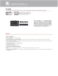
1
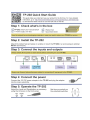
K R A ME R E LE CT R O N IC S L TD . USER MANUAL MODEL: TP-202 UXGA Line Transceiver/DA P/N: 2900-000226 Rev 5 Contents 1 Introduction 1 2 2.1 2.2 2.3 3 3.1 3.2 3.3 4 4.1 Getting Started Achieving the Best Performance Safety Instructions Recycling Kramer Products Overview About the Power Connect™ Feature Shielded Twisted Pair (STP) / Unshielded Twisted Pair (UTP) Defining the TP-202 UXGA Line Transceiver/DA Connecting the TP-202 Wiring the TP LINE IN / LINE OUT RJ-45 Connectors 2 2 3 3 4 4 5 5 7 9 5 Technical Specifications 10 Figures Figure 1: TP-202 UXGA Line Transceiver/DA Figure 2: TP-202 (Underside Panel) Figure 3: Connecting the TP-202 UXGA Line Transceiver/DA Figure 4: TP PINOUT TP-202 – Contents 5 6 8 9 i 1 Introduction Welcome to Kramer Electronics! Since 1981, Kramer Electronics has been providing a world of unique, creative, and affordable solutions to the vast range of problems that confront video, audio, presentation, and broadcasting professionals on a daily basis. In recent years, we have redesigned and upgraded most of our line, making the best even better! Our 1,000-plus different models now appear in 11 groups that are clearly defined by function: GROUP 1: Distribution Amplifiers; GROUP 2: Switchers and Routers; GROUP 3: Control Systems; GROUP 4: Format/Standards Converters; GROUP 5: Range Extenders and Repeaters; GROUP 6: Specialty AV Products; GROUP 7: Scan Converters and Scalers; GROUP 8: Cables and Connectors; GROUP 9: Room Connectivity; GROUP 10: Accessories and Rack Adapters and GROUP 11: Sierra Products. Congratulations on purchasing your Kramer TP-202 UXGA Line Transceiver/DA, which is ideal for the following typical applications: Presentation and multimedia applications Long-range graphics distribution for schools, hospitals, security, and stores TP-202 - Introduction 1 2 Getting Started We recommend that you: Unpack the equipment carefully and save the original box and packaging materials for possible future shipment Review the contents of this user manual i 2.1 Go to http://www.kramerelectronics.com to check for up-to-date user manuals, application programs, and to check if firmware upgrades are available (where appropriate). Achieving the Best Performance To achieve the best performance: Use only good quality connection cables (we recommend Kramer highperformance, high-resolution cables) to avoid interference, deterioration in signal quality due to poor matching, and elevated noise levels (often associated with low quality cables) Do not secure the cables in tight bundles or roll the slack into tight coils Avoid interference from neighboring electrical appliances that may adversely influence signal quality Position your Kramer TP-202 away from moisture, excessive sunlight and dust ! 2 This equipment is to be used only inside a building. It may only be connected to other equipment that is installed inside a building. TP-202 - Getting Started 2.2 Safety Instructions ! 2.3 Caution: There are no operator serviceable parts inside the unit Warning: Use only the Kramer Electronics input power wall adapter that is provided with the unit Warning: Disconnect the power and unplug the unit from the wall before installing Recycling Kramer Products The Waste Electrical and Electronic Equipment (WEEE) Directive 2002/96/EC aims to reduce the amount of WEEE sent for disposal to landfill or incineration by requiring it to be collected and recycled. To comply with the WEEE Directive, Kramer Electronics has made arrangements with the European Advanced Recycling Network (EARN) and will cover any costs of treatment, recycling and recovery of waste Kramer Electronics branded equipment on arrival at the EARN facility. For details of Kramer’s recycling arrangements in your particular country go to our recycling pages at http://www.kramerelectronics.com/support/recycling/. TP-202 - Getting Started 3 3 Overview The TP-202 is a twisted pair branching receiver for computer graphics video signals with resolutions from VGA up to UXGA and higher or HDTV signals. It takes a twisted pair signal and converts it into a computer graphics video signal or HDTV signal available on two 15-pin HD outputs, and simultaneously re-transmits the original twisted pair signal to another compatible receiver. The TP-202 UXGA Line Transceiver/DA features: A transmission range of more than 300ft (more than 100m) HD signal reception (high-definition resolutions: 480p, 576p, 720p, 1080i and 1080p) Two UXGA outputs on 15-pin HD connectors EQ. and LEVEL controls Selectable polarity for decoding H and V Sync for UXGA graphics A 12V DC power supply and it can power or be powered by the receiver over the same CAT 5 cable 3.1 A CAT 5 output for transmitting the signal to an additional receiver About the Power Connect™ Feature The Power Connect feature applies as long as the cable can carry power. This feature is available when using STP cable and the distance does not exceed 50m (164ft) on standard CAT 5 cable. For longer distances, use heavier gauge cable (TP cable is still suitable for the video/audio transmission, but not for feeding the power at these distances). For units that are connected via RJ-45 connectors, make sure that the shield of the STP cable is connected to the metal casing of the connectors on both ends of the cable. For units that are connected via terminal block connectors, the shield of the STP cable must be connected to a ground terminal on the units at both ends (use the ground terminal of the power supply connection if necessary). For a TP cable exceeding a distance of 50m, separate power supplies should be connected to the transmitter and to the receiver simultaneously. 4 TP-202 - Overview 3.2 Shielded Twisted Pair (STP) / Unshielded Twisted Pair (UTP) We recommend that you use Shielded Twisted Pair (STP) cable, and stress that the compliance to electromagnetic interference was tested using STP cable. There are different levels of STP cable available, and we advise you to use the best quality STP cable that you can afford. Our non-skew-free cable, Kramer BC-STP is intended for analog signals where skewing is not an issue. In cases where there is skewing, our Unshielded Twisted Pair (UTP) skew-free cable, Kramer BC-XTP, may be advantageous, and UTP cable might also be preferable for long range applications. In any event when using UTP cable, it is advisable to ensure that the cable is installed far away from electric cables, motors and so on, which are prone to create electrical interference. 3.3 Defining the TP-202 UXGA Line Transceiver/DA This section defines the TP-202. Figure 1: TP-202 UXGA Line Transceiver/DA TP-202 - Overview 5 # 1 Feature Function EQ. Trimmer Adjust the cable compensation equalization level Insert a screwdriver into the small hole and carefully rotate it, to trim the appropriate level 2 LEVEL Trimmer Adjust the output signal level 3 UXGA OUT 1 15-pin HD Connector Connect to the first UXGA acceptor 4 UXGA OUT 2 15-pin HD Connector Connect to the second UXGA acceptor 5 ON LED Illuminates when receiving power 6 LINE OUT RJ-45 Connector Connect to the LINE IN connector on an additional TP-202 Using a UTP CAT 5 cable with RJ-45 connectors at both ends (the PINOUT is defined in 4.1) 7 LINE IN RJ-45 Connector Connect to the LINE OUT RJ-45 connector on the transmitter 8 12V DC +12V DC connector for powering the unit For example, the PT-110, as Figure 3 illustrates Figure 2 defines the TP-202 underside panel: Figure 2: TP-202 (Underside Panel) # Feature Function 1 VS Switch Slide the switch to NORMAL to retain the polarity Slide the switch to INVERT to invert the VS polarity 2 HS Switch Slide the switch to NORMAL to retain the polarity Slide the switch to INVERT to invert the HS polarity By default, both switches are set to NORMAL By default, both switches are set to NORMAL 6 TP-202 - Overview 4 Connecting the TP-202 i Always switch off the power to each device before connecting it to your TP-202. After connecting your TP-202, connect its power and then switch on the power to each device. You can use the TP-202 UXGA Line Transceiver/DA to configure a UXGA DA system. This lets you transmit a computer graphics signal to two displays via long line CAT 5 UTP cabling. By using two TP-202 units, you can transmit the signal to an additional TP-202. To connect the TP-202, as the example in Figure 3 illustrates, do the following: 1. Connect a transmitter (for example, the Kramer PT-110 UXGA Line Transmitter) to the LINE IN RJ-45 connector via CAT 5 cabling, see Section 4.1. You can also connect an HD transmitter, such as the Kramer TP-219HD. 2. Set the VS and HS switches on the underside of the unit to NORMAL. 3. Connect the UXGA OUT 1 15-pin HD connector to an UXGA acceptor (for example, display 1). 4. Connect the UXGA OUT 2 15-pin HD connector to an UXGA acceptor (for example, display 2). 5. Check the image on the display. If it is not stable, set the VS and HS switches to INVERT to obtain a stable image. 6. If required, connect the LINE OUT RJ-45 connector on the TP-202 to an additional TP-202. Up to six units may be connected with minimal deterioration. The combined length between the first and the last unit may exceed 300 meters. 7. If required, adjust the video output signal level and/or cable compensation equalization level. Use a screwdriver to carefully rotate the trimmer, adjusting the appropriate level 8. If necessary, set the HS and VS switches on the TP-202 underside. By default, both switches are set to normal (see Figure 2). 9. Connect the 12V DC power adapter to the power socket and connect the adapter to the mains electricity (not shown in Figure 3). The signal from the UXGA source is transmitted via CAT 5 cable to the TP-202 - Connecting the TP-202 7 TP-202, decoded and converted at the UXGA OUT 1 and UXGA OUT 2 15-pin HD connectors to the UXGA acceptors simultaneously. ! When chaining several units, we recommend using an STP cable between the transmitter and the receiver and a skew-free cable for connecting the TP-202 units. When using the TP-202 as a standalone, we recommend using UTP cables. Figure 3: Connecting the TP-202 UXGA Line Transceiver/DA 8 TP-202 - Connecting the TP-202 4.1 Wiring the TP LINE IN / LINE OUT RJ-45 Connectors This section defines the TP pinout, using a straight pin-to-pin cable with RJ-45 connectors. i Note, that the cable Ground shielding must be connected / soldered to the connector shield. EIA /TIA 568B PIN 1 Wire Color Orange / White 2 Orange 3 Green / White 4 Blue 5 Blue / White 6 Green 7 Brown / White 8 Brown TP-202 - Connecting the TP-202 Figure 4: TP PINOUT 9 5 Technical Specifications INPUT: 1 CAT 5 LINE IN on an RJ-45 connector OUTPUTS: 1 CAT 5 LINE OUT on an RJ-45 connector 2 UXGA on 15-pin HD connectors MAX. OUTPUT LEVEL: 1.5Vpp RESOLUTION: Up to UXGA, up to 1080p DIFF. GAIN: 2.8% DIFF. PHASE: 0.2Deg K-FACTOR: 0.1% S/N RATIO: 69.2dB @5MHz CONTROLS: Level: -9.6dB to +2.3dB; Equalization: 0dB to 36.3dB @50MHz COUPLING: Receiver section: DC, looping section: AC POWER CONSUMPTION: 12V, 525mA maximum current (when feeding TP-219HD (as the transmitter) and a looped TP-202) OPERATING TEMPERATURE: 0° to +40°C (32° to 104°F) STORAGE TEMPERATURE: -40° to +70°C (-40° to 158°F) HUMIDITY: 10% to 90%, RHL non-condensing DIMENSIONS: 12.1cm x 7.18cm x 2.42cm (4.76" x 2.83" x 0.95"), W, D, H WEIGHT: 0.3kg (0.67lbs) approx. ACCESSORIES: Power supply OPTIONS: RK−3T 19" rack adapter Specifications are subject to change without notice at http://www.kramerelectronics.com 10 TP-202 - Technical Specifications For the latest information on our products and a list of Kramer distributors, visit our Web site where updates to this user manual may be found. We welcome your questions, comments, and feedback. Web site: www.kramerelectronics.com E-mail: [email protected] ! P/N: SAFETY WARNING Disconnect the unit from the power supply before opening and servicing 2900- 000226 Rev: 5