1
Wireless N150 Mini AP/Router
Wireless N150 Mini AP/Router
Copyright Statement
is the registered trademark of Shenzhen Tenda
Technology Co., Ltd. All the products and product names
mentioned herein are the trademarks or registered trademarks of
their respective holders. Copyright of the whole product as
integration, including its accessories and software, belongs to
Shenzhen Tenda Technology Co., Ltd. Without prior expressed
written permission from Shenzhen Tenda Technology Co., Ltd, any
individual or party is not allowed to copy, plagiarize, reproduce, or
translate it into other languages.
All photos and product specifications mentioned in this manual
are for references only. Upgrades of software and hardware may
occur; Tenda reserves the right to revise this publication and to
make changes in the content hereof without obligation to notify
any person or organization of such revisions or changes. If you
would like to know more about our product information, please
visit our website at http://www.tendacn.com.
Wireless N150 Mini AP/Router
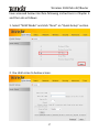
Table of Contents
Wireless N150 Mini AP/Router
Wireless N150 Mini AP/Router
Wireless N150 Mini AP/Router
Wireless N150 Mini AP/Router
Chapter 1 Product Overview
Thanks for purchasing this A6 Wireless N150 Mini AP/Router
(hereunder referred to as device).
A6 is a typically multi-purpose device that provides 5
working modes: Wireless AP Mode, Wireless Router Mode, WISP
Mode, Client Mode and Universal Repeater Mode, meeting your
diversified needs.
Plus, it can either be powered by an included power adapter
or your PC via an included USB cable.
Super mini design with ultimate powerful functionalities,
fitting diversified wireless applications, and the device is an idea
choice for businessmen and fashion follower.
1.1 Features
Delivers up to 150Mbps wireless data rate.
Provides 5 working modes: wireless AP, wireless router,
WISP, client and Universal repeater modes.
64-/128-bit WEP, WPA and WPA2 secure your wireless
network against unauthorized access.
1 10/100Mbps Ethernet port for Internet/LAN connection.
Can be connected to an XDSL/Cable MODEM; support
Dynamic/Static IP Internet connection.
Local/remote web based management.
Adopts wireless Roaming technology to ensure high
1
Wireless N150 Mini AP/Router
efficient and reliable wireless connection.
MAC-based access control.
Syslog records device's usage status.
Support automatic or manual select of IEEE802.11 mode
(network mode).
Provides UPnP, DDNS, virtual server and DMZ features.
Disallow/allow specified LAN users to access Internet.
Internal firewall protects against potential attacks from
hackers .
Provides USB or external AC adapter as a power source.
1.2 Package Contents
Please unpack the box and check the following items:
◆ A6 Wireless N150 Mini AP/Router
◆ Power Adapter
◆ USB Cable
◆ Quick Installation Guide
◆ CD-ROM
If any of the above items are incorrect, missing, or damaged,
please contact your Tenda reseller for immediate replacement.
2
Wireless N150 Mini AP/Router
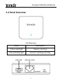
1.3 Panel Overview
LED Overview
Status
Description
A blue solid light
Device is starting
A blue blinking light
Device is working normally
3
Wireless N150 Mini AP/Router
LED/Button Overview
Reset: Reset button. Pressing it for about 7 seconds restores
the device to factory defaults.
Power: Power receptacle for connection to power outlet via
the included power adapter or to one USB port on your
notebook using the included USB cable.
LAN/WAN: LAN/WAN interchangeable port. The port
functions as a WAN port for connection to a DSL MODEM or
other network devices in Wireless Router mode and as a
LAN port for connection to a PC or an Ethernet switch, etc.
in wireless AP, Repeater, Client or WISP mode.
4
Wireless N150 Mini AP/Router
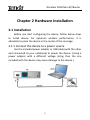
Chapter 2 Hardware Installation
2.1 Installation
Before you start configuring the device, follow below steps
to install device. For optimum wireless performance, it is
advisable to place the device in the center of the coverage.
2.1.1 Connect the device to a power source
Use the included power adapter or USB cable (with the other
end connected to your notebook) to power the device. (Using a
power adapter with a different voltage rating than the one
included with the device may cause damage to the device.)
5
Wireless N150 Mini AP/Router
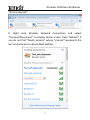
2.1.2 Connect your notebook to the device
2.1.2.1. If you are using a wired adapter, connect your
notebook to the device using an Ethernet cable.
2.1.2.2. If you are using a wireless adapter, follow steps
below to config your adapter:
a. Click “Start”→ ”Control Panel” → “Network and Internet”
→”Network and Internet Sharing Center”→“ Change adapter
settings”. As seen below, Wireless Network Connection displays
6
Wireless N150 Mini AP/Router
“Not Connected”.
b. Right click Wireless Network Connection and select
“Connect/Disconnect” to display below screen. Click “Refresh” if
you do not find “Tenda_××××××”, where “××××××” represents the
last six characters in device MAC address.
7
Wireless N150 Mini AP/Router
c. Select “Tenda_××××××”and click “Connect”.
Chapter 3 Working Modes Overview
The device provides 5 working modes and is preset to
wireless AP mode by default. You can select a mode that best fits
yourself and the device delivers corresponding functions
accordingly.
3.1 Wireless AP Mode
In this mode, the device converts the wired signal into
wireless signals, extending existing network coverage. It works as
a central access point for multiple wireless clients (generally,
wireless adapters) concurrently. Simply connect the device to
Internet-enabled broadband at hotel, home or office without
configuration required on the device and multiple users can share
Internet access. Note that you must config same security settings
on your adapter to connect to the device if you encrypt the
device wireless network. This mode is also your best choice if
there is already a wired router on existing network. Simply
connect the device to the wired router using an Ethernet cable
(For details, refer to section 5-1). Refer to below topology for
connecting network devices involved when using this mode.
8
Wireless N150 Mini AP/Router
3.2 Wireless Router Mode
In this mode,the device works as a wireless NAT router with
DHCP feature. Simply connect the device to a DSL/cable modem,
and a wireless network is created to be shared by multiple
wireless clients.
Refer to below topology for connecting network devices
involved when using this mode.
5-2 For more info, see section 5-2 hereof
9
Wireless N150 Mini AP/Router
3.3 WISP Mode
In this mode, the device functions as a wireless signal
amplifier, ideal for wifi hot spot access and bridging, and provides
NAT and DHCP server features. You only need to config some
simple settings on the device to wirelessly connect to the other
Internet-enabled wireless device without configuring it, so that
multiple users can share the Internet connection via the device. If
you would like more PCs using wired adapters to share this
connection, then simply connect a switch to the device.
Refer to below topology for deploying network devices
involved when using this mode.
5-2 For more info, see section 5-3 hereof
3.4 Client Mode
In this mode, the device is equivalent to a wireless adapter that
enables a PC without an installed wireless network adapter to
connect to a wireless network for Internet connection. Note that
10
Wireless N150 Mini AP/Router
the DHCP server is deactivated by default in this mode to avoid
potential collision and the Ethernet port is working as a LAN port
only, so you must config TCP/IP settings manually on your PC to
connect to the device using an Ethernet cable.
It’s best for connecting your multimedia player, IPTV set-top
box or other internet-enabled device to a wireless network.
Refer to below topology for deploying network devices
involved when using this mode.
For details, see section 5-4.
3.5 Universal Repeater Mode
In this mode, the device delivers wireless repeating function
and amplifies wireless signal without changing network topology.
Use this mode to amplify and transmit wireless signal when
sharing wireless Internet connection with your neighbors.
It is best for use with an IPTV set-top box, broadband
satellite receptor or for purpose of extending existing coverage.
11
Wireless N150 Mini AP/Router
Refer to below topology for deploying network devices
involved when using this mode.
For details, see section 5-5.
12
Wireless N150 Mini AP/Router
Chapter 4 Login to Web Utility
This chapter presents how to access device Web Utility.
Follow below instructions if you are using Windows 7.
4.1 Using a wired connection
4.1.1 Config TCP/IP settings
If you are connecting to the device via an Ethernet cable, do as
follows to config TCP/IP settings on your PC.
1. Right click “Network” on your desktop and select “Properties”.
2. Click “Change adapter settings”.
13
Wireless N150 Mini AP/Router
3. Right click “Local Area Connection” and select “Properties”.
4. Select “Internet Protocol (TCP/IP)” on the appearing window
and click the “Properties” button.
14
Wireless N150 Mini AP/Router
5. Select “Use the following IP address” or “Obtain an IP address
automatically”.
a. To “Obtain an IP address automatically” simply click the
corresponding button.
15
Wireless N150 Mini AP/Router
b. “Use the following IP address”
IP address: Enter 192.168.2.xxx (xxx can be any value from
2~253).
Subnet mask: Enter 255.255.255.0.
Default gateway: Enter 192.168.2.1.
Preferred DNS server: Enter 192.168.2.1 in case that you don’t
know the local DNS server address (Or contact your ISP for help).
At last, click OK to save your settings.
16
Wireless N150 Mini AP/Router
4.2 If you are connecting to the device
wirelessly, do as follows
(Note that you can only connect to the device wirelessly when
using Wireless Router or AP mode.)
1. Click “Network”-“Properties” and then left click “Change
adapter settings” to open network connection screen. And you
will see the wireless connection displays “Not connected”.
17
Wireless N150 Mini AP/Router
2. Click the “Wireless Network Connection”, select “Properties”
and then refer to steps 4-5 above to config TCP/IP settings for the
wireless adapter.
3. Right click “Wireless Network Connection” and select
“Connect/Disconnect” to display all scanned wireless networks.
18
Wireless N150 Mini AP/Router
4. Select the SSID entitled “Tenda_××××××” (where××××××
represents the last 6 characters in the device MAC address) and
click “Connect”. If you don’t find it, please click “Refresh Network
List”.
4.3 Login to Web Utility
Launch a web browser, input “http://192.168.2.1”and press
“Enter” after you configured the TCP/IP settings on your PC.
19
Wireless N150 Mini AP/Router
Enter “admin” (factory default password) in the Password field
and click “Login”.
You will see below screen if you entered a correct password.
20
Wireless N150 Mini AP/Router
Chapter 5 Quick Setup for Internet Access
in 5 Working Modes
5.1 Quick Setup----Wireless AP Mode
The device is in Wireless AP mode by default. So simply
connect the device to Internet service at hotel, home or office
without configuration required on the device and multiple users
within coverage can share Internet access. Just remember to set
all wireless clients to “obtain an IP address automatically”.
Refer to below topology for connecting network devices when
using this mode.
Note: Normally, internet access in hotels is DHCP/dynamic IP,
which means devices connecting to the network can obtain IP
addresses automatically. However, if you’re not able to obtain an
IP address, ask the hotel network administrator for an available IP
address and configure it manually on your PC.
21
Wireless N150 Mini AP/Router
5.2 Quick Setup----Wireless Router Mode
In this mode,the device works as a wireless NAT router with
DHCP feature. Simply connect the device to an Internet-enabled
DSL/CABLE modem from your ISP side, and multiple wireless
clients can share this single Internet connection using IP
addresses obtained from the device’ DHCP server.
Note:In the Wireless Router mode, the device Ethernet port
works as a WAN port for Internet connection, so you can only
access the router’s Web utility via a wireless connection.
To config settings in this mode, first make sure you have accessed
below interface following instructions in Chapter 4 and then do as
follows:
1. Select “Wireless Router” and then click “Next” on the Quick
Setup interface.
2. You will see the interface below.
22
Wireless N150 Mini AP/Router
SSID :A SSID (Service Set Identifier) is the unique name of
a wireless network.
Channel: Select a least interferential channel for your
wireless network to operate on from the drop-down list. If
you’re not sure of it, select auto.
Security Mode: Select WEP, WPA or WPA2 to encrypt your
wireless network.
For security purpose, it is advisable to encrypt your wireless
network with WPA-AES. Simply enter a security key made up of
8-63 numeric, alphabetic characters or signs like @, # and $, etc.
For detailed configurations, refer to later sections hereof.
After you finish above settings, click “Next”.
3. Below screen allows you to config your Internet connection
settings.
23
Wireless N150 Mini AP/Router
Three Internet connection types are provided: PPPOE,
Dynamic IP and Static IP. Select your connection type. If you are
not sure about which to select, consult your ISP.
DHCP
This is the default connection type. No configurations are
required for this connection. Simply click “Next” to complete
settings.
Static IP
If your ISP offers you static IP Internet connection type,
select “Static IP" from corresponding drop-down menu, enter IP
address, subnet mask, Primary DNS and secondary DNS
(optionary) info provided by your ISP in corresponding fieldsand
then click “Next”.
24
Wireless N150 Mini AP/Router
PPPoE
Select PPPoE, if your ISP is using a PPPoE connection, enter the
PPPoE user name and password provided by your ISP in
corresponding fields as seen below and then click “Next”.
After the device is rebooted, go to “Status” to check the WAN
connection status. If it shows “Connected”, it indicates you can
25
Wireless N150 Mini AP/Router
start surfing Internet now. For more settings, see later sections
hereof.
Config WAN MAC address (Optional)
Normally you don't need to change the default WAN MAC
address. However, some ISP may bind a specific MAC address for
Internet connection authentication. In this case, you will be
provided with a valid MAC address, simply enter such MAC in the
WAN MAC Address field. If you unfortunately forget it, consult
your ISP for help.
WAN MAC Address: Displays device's current WAN MAC
address, you can manually change it.
Restore to Factory Default MAC: Click it to restore router’s
WAN MAC to factory default value.
Clone MAC: Click to copy your PC’s MAC to router’s WAN
MAC Address field.
4. Click “Finish” and reboot the device to activate new settings.
5.3 Quick Setup----WISP Mode
To config Internet connection in WISP mode, first make sure you
26
Wireless N150 Mini AP/Router
have accessed below interface following instructions in Chapter 4
and then do as follows:
1. Select “WISP Mode” and click “Next” on “Quick Setup” section.
2. You shall come to below screen.
27
Wireless N150 Mini AP/Router
Remote AP's SSID: Service Set Identifier), unique wireless
network name; Enter a SSID of the link partner (to which
your device is going to connect).
Remote AP's Channel: Select the channel which the link
partner (to which the device is going to connect) is currently
operating on.
Remote AP's MAC Address: Enter the MAC address (also
called BSSID) of the link partner (to which the device is
going to connect).
Security Mode: Config same security settings (including
security key) set on the link partner here on your device.
For detailed configurations, refer to Wireless---->Security
section.
28
Wireless N150 Mini AP/Router
For convenience purpose, it is advisable to use the “Open Scan”
option to search and select the link partner to add certain
settings to the device automatically.
After you finish the above settings, click “Next”.
3. Below screen shall display.
SSID: Service Set Identifier), unique wireless network name;
Define a wireless network name (SSID) for the device.
Channel: Select a channel from the drop-down menu for
the device to operate on. There are 13 channels available.
For security purpose, it is advisable to encrypt your wireless
network with WPA-AES. Simply enter a security key made up of
8-63 numeric, alphabetic and characters. For detailed
configurations, refer to section7.2 hereof.
Note: It is strongly recommended not to change the channel
settings when using this mode, as improper change may cause
connection failure. After you finish above settings, click “Next”.
After finishing above settings, set PCs to “Obtain an IP address
automatically”.
29
Wireless N150 Mini AP/Router
5.4 Client Mode
To config Internet connection settings in the Client Mode, first
make sure you have accessed below interface following
instructions in Chapter 4 and then do as follows:
1. Select “Client Mode” and click “Next”.
2. Below screen shall display.
30
Wireless N150 Mini AP/Router
For
Remote AP's SSID: Service Set Identifier), unique wireless
network name; Enter a SSID of the link partner (to which
your device is going to connect).
Remote AP's Channel: Select the channel which the link
partner (to which the device is going to connect) is currently
operating on.
Remote AP's MAC Address: Enter the MAC address (also
called BSSID) of the link partner (to which the device is
going to connect).
Security Mode: Config same security settings (including
security key) set on the link partner here on your device.
For detailed configurations, refer to Wireless---->Security
section.
convenience purpose, it is advisable to use the “Open Scan”
31
Wireless N150 Mini AP/Router
option to search and select the link partner to add certain
settings to the device automatically.
After you finish the above settings, click “Finish” and reboot the
device to activate new settings.
5.5 Universal Repeater Mode
To config Internet connection settings in the Universal Repeater
Mode (also referred to Client + AP Mode), first make sure you
have accessed below interface following instructions in Chapter 4
and then do as follows:
1. Select “Universal Repeater Mode” and click “Next”.
32
Wireless N150 Mini AP/Router
2. Below screen shall display.
Remote AP's SSID: Service Set Identifier), unique wireless
network name; Enter a SSID of the link partner (to which
your device is going to connect).
Remote AP's Channel: Select the channel which the link
33
Wireless N150 Mini AP/Router
partner (to which the device is going to connect) is currently
operating on.
Remote AP's MAC Address: Enter the MAC address (also
called BSSID) of the link partner (to which the device is
going to connect).
Security Mode: Config same security settings (including
security key) set on the link partner here on your device.
For detailed configurations, refer to Wireless---->Security
section.
For convenience purpose, it is advisable to use the “Open Scan”
option to search and select the link partner to add certain
settings to the device automatically.
After you finish the above settings, click “Next”.
3. Below screen shall display.
SSID: Service Set Identifier), unique wireless network name;
Define a wireless network name (SSID) for the device.
34
Wireless N150 Mini AP/Router
Channel: Select a channel from the drop-down menu for
the device to operate on. There are 13 channels available.
For security purpose, it is advisable to encrypt your wireless
network with WPA-AES. Simply enter a security key made up of
8-63 numeric, alphabetic characters or signs like @, # and $, etc.
For detailed configurations, refer to later sections hereof.
Note: It is strongly recommended not to change the channel
settings when using this mode, as improper change may cause
connection failure. After you finish above settings, click “Next”.
4. Click “Finish” and reboot the device to activate new settings.
Note: The device must share identical channel, security (including
security key), extension channel (if any) settings with the link
partner to achieve successful connection in this mode.
35
Wireless N150 Mini AP/Router
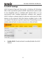
Chapter 6 Network
6.1 LAN Settings
This section allows you to config the TCP/IP settings for the
device’s LAN interface. Settings to config vary depending on
different working modes.
1.
If you are currently using the WISP/Wireless Router Mode,
see below:
IP Address: Device’s LAN IP, 192.168.2.1 by default. You can
change it according to your needs; just remember to use
the new one to log on to the device’s web utility if you
changed it.
Subnet Mask: Device’s LAN subnet mask, 255.255.255.0 by
default.
2. If you are currently using the Wireless AP/Client/Universal
Repeater Mode, see below:
36
Wireless N150 Mini AP/Router
IP Address: Device’s LAN IP, 192.168.2.1 by default. You can
change it according to your needs; just remember to use
the new one to log on to the device’s web utility if you
changed it.
Subnet Mask: Device’s LAN subnet mask, 255.255.255.0 by
default.
Gateway: Enter the Gateway address provided by your ISP.
Note: If you change the device’s LAN IP address, you must use the
new one to logon to the web-based configuration utility.
6.2 WAN Settings
This section is only available in WISP Mode and Wireless Router
Mode.
37
Wireless N150 Mini AP/Router
PPPoE
Internet connection Type: Displays the current Internet
connection type.
User Name: Enter the User Name provided by your ISP.
Password: Enter the password provided by your ISP.
MTU: Maximum Transmission Unit. DO NOT change it from
the factory default of 1480 unless necessary. You may need
to change it for optimal performance with some specific
websites or application software that cannot be opened or
enabled; in this case, try 1450, 1400, etc.
Service Description: Description of PPPoE connection.
Leave blank unless necessary.
Server Name: Description of server. Leave blank unless
necessary.
38
Wireless N150 Mini AP/Router
Static IP
If your ISP assigns a fixed IP address to you, then select Static IP,
and enter the IP address, subnet mask, primary DNS and
secondary DNS(optional) info provided by your ISP in
corresponding fields.
IP Address: Enter the WAN IP address provided by your ISP.
Consult your ISP if you are not clear.
Subnet Mask: Enter WAN Subnet Mask provided by your ISP.
The default is 255.255.255.0.
Gateway: Enter the WAN Gateway provided by your ISP.
Primary DNS Server: Enter the DNS address provided by
your ISP.
Secondary DNS Server: Enter the other DNS address if your
ISP provides 2 such addresses (optional).
39
Wireless N150 Mini AP/Router
6.3 MAC Clone
The MAC clone feature is only available in Wireless Router mode.
This section allows you to config the device WAN MAC address.
Normally you don't need to change the default WAN MAC
address. However, some ISP may bind a specific MAC address for
Internet connection authentication. In this case, you will be
provided with a valid MAC address, simply enter such MAC in the
WAN MAC Address field. If you unfortunately forget it, consult
your ISP for help.
WAN MAC Address: Displays device's current WAN MAC
address, you can manually change it.
Restore to Factory Default MAC: Click it to restore router’s
WAN MAC to factory default value.
Clone MAC: Click to copy your PC’s MAC to device’s WAN
MAC Address field.
40
Wireless N150 Mini AP/Router
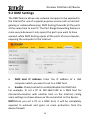
6.4 DNS
DNS is short for Domain Name System or Domain Name
Service. It resolves catchy domain names into corresponding IP
addresses.
DNS: Check/uncheck to enable/disable the DNS feature.
Primary DNS Server: Enter the DNS address provided by
your ISP.
Secondary DNS Server: Enter the other DNS address if your
ISP provides 2 such addresses (optional).
41
Wireless N150 Mini AP/Router
Chapter 7 Wireless
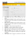
7.1 Basic Settings
Note: Below screen will not be displayed when in “Client Mode”.
802.11 Mode: Select a right mode according to your
wireless client.
11b mode:Select it if you have only Wireless-B clients in
your wireless network.
11g mode:Select it if you have only Wireless-G clients in
your wireless network.
11b/g mixed mode: Select it if you have only Wireless-B
and Wireless-G clients in your wireless network.
11b/g/n mixed mode: Select it if you have Wireless-B,
Wireless-G and Wireless-N clients in your wireless network.
SSID :A SSID (Service Set Identifier) is the unique name of
a wireless network. It is configurable.
42
Wireless N150 Mini AP/Router
BSSID :A BSSID, in IEEE 802.11 wireless network, is the
MAC address of a wireless AP.
SSID Broadcast: Select “Enable”/“Disable” to make your
wireless network visible/ invisible to any wireless clients
within coverage when they perform a scan to see what’s
available. When disabled, this SSID becomes invisible to any
wireless clients within the coverage. Manually enter the
SSID if you want to connect to it. By default, it is enabled.
Channel: For an optimal wireless performance, you may
select the least interferential channel for your wireless
network to operate on from the drop-down list. There are
13 channels available. Select Auto if you are not sure of it.
Channel Bandwidth: Select a proper channel bandwidth to
enhance wireless performance. When there are11b/g and
11n wireless clients, select 20/40M; when there are only
non-11n wireless clients, select 20M; when the wireless
network mode is 11n mode, please select 20/40M to boost
throughput.
Extension Channel:Working network frequency range for
11n mode.
7.2 Wireless Security
This section allows you to encrypt your wireless network to
block unauthorized accesses and malicious packet sniffing with
WEP, WPA and WPA2. For better security, it is advisable to use the
WPA-AES encryption.
43
Wireless N150 Mini AP/Router
7.2.1 WPA-PSK
The WPA protocol implements the majority of the IEEE
802.11i standard. It enhances data encryption through the
Temporal Key Integrity Protocol (TKIP) which is a 128-bit
per-packet key, meaning that it dynamically generates a new key
for each packet. WPA also includes a message integrity check
feature to prevent data packets from being hampered with. Only
authorized network users can access the wireless network.
Cipher Type: Select either AES (advanced encryption
standard) or TKIP (temporary key integrity protocol) type.
Security Key: Enter a security key,which must be between
8-63 ASCII characters.
Key Renewal Interval: Enter a valid time period for the key.
44
Wireless N150 Mini AP/Router
7.2.2 WPA2-PSK
The later WPA2 protocol features compliance with the full IEEE
802.11i standard and uses Advanced Encryption Standard (AES) in
addition to TKIP encryption protocol to guarantee better security
than that provided by WEP or WPA.
Cipher Type: Select one cipher type from AES (advanced
encryption standard), TKIP (temporary key integrity protocol)
or TKIP&AES.
Security Key: Enter a security key,which must be between
8-63 ASCII characters.
Key Renewal Interval: Enter a valid time period for the key.
7.2.3 WEP
WEP ,
based on RC4, is intended to provide data
45
Wireless N150 Mini AP/Router
confidentiality comparable to that of a traditional wired network.
Two methods of authentication can be used with WEP: Open
System authentication and Shared Key authentication.
Security Mode: Select WEP from the drop-down menu.
Default Key: Select a currently valid key from keys 1-4.
WEP Key1/2/3/4: Enter 5 or 13 ASCII characters (Invalid
characters like / “‘and so on are not allowed) if you select
ASCII or enter 10 or 26 HEX characters if you select Hex.
Note that you must enter the key content in the
corresponding format selected.
46
Wireless N150 Mini AP/Router
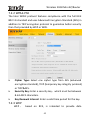
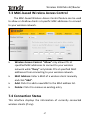
7.3 MAC-based Wireless Access Control
The MAC-based Wireless Access Control feature can be used
to allow or disallow clients at specific MAC addresses to connect
to your wireless network.
Wireless Access Control: “Allow” only allows PCs at
specified MAC addresses to connect to your wireless
network while “Deny” only blocks PCs at specified MAC
addresses from connecting to your wireless network.
MAC Address: Enter a MAC of a wireless client manually
and click “Add”.
Add: Click it to add a new MAC to the MAC address list.
Delete: Click it to remove an existing entry.
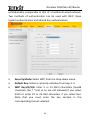
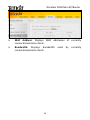
7.4 Connection Status
This interface displays the information of currently connected
wireless clients (if any).
47
Wireless N150 Mini AP/Router
MAC Address: Displays MAC addresses of currently
connected wireless clients.
Bandwidth: Displays bandwidth used by currently
connected wireless clients.
48
Wireless N150 Mini AP/Router
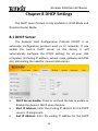
Chapter 8 DHCP Settings
The DHCP server feature is only available in WISP Mode and
Wireless Router Mode.
8.1 DHCP Server
The Dynamic Host Configuration Protocol (DHCP) is an
automatic configuration protocol used on IP networks. If you
enable the built-in DHCP server on the device, it will
automatically configure the TCP/IP settings for all your LAN
computers (including IP address, subnet mask, gateway and DNS
etc), eliminating the need for manual intervention.
DHCP Server-Enable: Check or uncheck the box to enable or
disable the device’s DHCP server feature.
Start IP Address: Enter the starting IP address for the DHCP
server’s IP assignment.
End IP Address: Enter the ending IP address for the DHCP
49
Wireless N150 Mini AP/Router
server’s IP assignment.
Lease Time: The length of time for the IP address lease.
Configuring a proper lease time improves the efficiency for
the DHCP server to reclaim disused IP addresses.
For example: If the lease time is set to one hour, then the DHCP
server will reclaim disused IP addresses every hour.
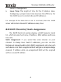
8.2 DHCP Client List/ Static Assignment
The DHCP Client List section displays a DHCP dynamic client
list, which includes host name, IP address, MAC address and lease
time info.
Static Assignment: If you would like some devices on your
network to always have fixed IP addresses, you can use this
feature and manually add a static DHCP assignment entry for each
such device. And then a registered MAC will get a correspondingly
reserved IP address while an unregistered MAC will be assigned
with an unused IP address.
50
Wireless N150 Mini AP/Router
IP Address: Enter the IP address for static DHCP assignment.
MAC Address: Enter the MAC address of a computer to
always receive the same IP address (the IP you just
specified).
Host name: Displays name of a given host (DHCP client).
Lease Time: Remaining time for a corresponding IP address
lease.
51
Wireless N150 Mini AP/Router
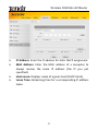
Chapter 9 Advanced Applications
The Port Range Forwarding feature is only available in WISP
Mode and Wireless Router Mode.
9.1 Port Range Forwarding
The Port Range Forwarding feature allows you to set up public
services on your network, such as web servers, ftp servers, e-mail
servers, or other specialized Internet applications.
When users send these types of requests to your network via the
Internet, the device will forward those requests to the
appropriate servers (computers). Before using forwarding, you
should assign static IP addresses to the designated servers.
If you need to forward all ports to one computer, go to DMZ.
Start/End Port: Enter the number or range of port(s) used
52
Wireless N150 Mini AP/Router
by the server or Internet applications.
LAN IP: Enter an IP address of the computer to work as a
server in LAN.
Protocol: Includes TCP, UDP and Both. Select “Both” when
you are not sure about which protocol to use.
Enable: Check the “Enable” option to activate a
corresponding entry next to it.
Delete: Check the “Delete” option to delete a
corresponding entry next to it.
Well-Known Service Port: The “Well-Known Service Port”
provides commonly used protocol ports. Select one from
them and then click the “Add to” button to automatically
add selected port to the Start Port-End Port fields of
selected entry ID. You can also manually add the ports
which are not included in the “Well-Known Service Port”.
Add to: Add a selected Well-Known Service Port to the Start
Port-End Port boxes of the entry you select.
For example: A LAN PC at 192.68.2.10 hosts WEB service on Port
80 and provides Telnet service on Port 23. To make such services
accessible to Internet users, config as shown on the screenshot
above.
Note: If you include port 80 on this section, you must set the port
on remote (web-based) management section to a different
number than 80, such as 8080, otherwise the Port Range
Forwarding feature may not take effect.
53
Wireless N150 Mini AP/Router
9.2 DMZ Settings
The DMZ feature allows one network computer to be exposed to
the Internet for use of a special-purpose service such as Internet
gaming or videoconferencing. DMZ hosting forwards all the ports
at the same time to one PC. The Port Range forwarding feature is
more secure because it only opens the ports you want to have
opened, while DMZ hosting opens all the ports of one computer,
exposing the computer to the Internet.
DMZ Host IP Address: Enter the IP address of a LAN
computer which you want to set to a DMZ host.
Enable: Check/uncheck to enable/disable the DMZ host.
For example: To set a PC at 192.168.2.100 to a DMZ host for
intercommunication with another host on the Internet, config
same settings as shown above on the screenshot on the device.
NOTE:Once you set a PC to a DMZ host, it will be completely
exposed to extranet and gains no more protection from the
device firewall.
54
Wireless N150 Mini AP/Router
9.3 UPnP Settings
UPnP (Universal Plug and Play) works in Windows XP, Windows
ME or later operational systems (NOTE: Operational system needs
to be integrated with or installed with Directx 9.0) or in an
environment with installed application software that supports
UPnP. It allows a network device to discover and connect to other
devices on the network. With this feature enabled, hosts in LAN
can request the device to perform special port forwarding so as to
enable external hosts to access resources on internal hosts.
Enable UPnP: Check/uncheck to enable/disable the UPnP
feature.
55
Wireless N150 Mini AP/Router
Chapter 10 Security
The Security feature is only available in WISP Mode and Wireless
Router Mode.
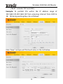
10.1 Client Filter
To better manage PCs in LAN, you can allow or disallow such
PCs to access certain ports on Internet using the Client Filter
functionality.
Click “Add” to enter page below:
56
Wireless N150 Mini AP/Router
Filter Mode: Select Deny or Allow according to your own
needs.
Deny Access to Internet: Disallow specified packets to pass
through the device; other packets are processed according
to default mode.
Allow Access to Internet: Allow specified packets to pass
through the device; other packets are processed according
to default mode.
Description: Enter a name of a new filter rule
IP Address: Specify a single IP address or an IP range.
Time: Select a time range for the rule to take effect.
Day: Select a day or several days for the rule to take effect.
WAN Port Range: Enter port number. You can specify a
range of ports or a single port. Allowed port ID ranges from
1 to 65535.
Traffic Type: Select a protocol or protocols for the traffic
57
Wireless N150 Mini AP/Router
(“Both” includes TCP and UDP).
Example: To prohibit PCs within the IP address range of
192.168.2.20-192.168.2.30 from accessing Internet from 8:00 to
18:00 during working days, do as follows:
Click “Save” and you will find such entry in the List below.
58
Wireless N150 Mini AP/Router
Select “Allow” from the “Default Mode” drop-down list and check
“Enable Client Filter” feature.
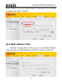
10.2 MAC Address Filter
To better manage PCs in LAN, you can use the MAC Address
Filter function to allow/disallow such PCs to access to Internet.
59
Wireless N150 Mini AP/Router
Click “Add” to enter page below:
Filter Mode: Select Deny or Allow according to your own
needs.
Deny Access to Internet: Disallow specified packets to pass
through the router; other packets are processed according
to default rule.
Allow Access to Internet: Allow specified packets to pass
through the router; other packets are processed according
to default rule.
Description: Simply describe a corresponding entry.
MAC Address: Enter the PC’s MAC address that you want to
filter out or select it from the MAC list.
Time: Select a time range for the corresponding entry to
take effect.
Day: select a day or several days for the corresponding
entry to take effect.
Example: To prevent a PC at the MAC address of
60
Wireless N150 Mini AP/Router
00:B0:0C:77:88:00 from accessing Internet from 8:00 to18:00
everyday, config same settings on the screenshot below on your
device:
Click “Save” to display the following page.
Select “Allow” from the “Default” drop-down list and check the
61
Wireless N150 Mini AP/Router
“Enable MAC Filter” feature.
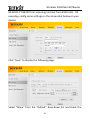
10.3 URL Filter
To better control LAN PCs, you can use the URL filter functionality
to allow or disallowsuch PC to access certain websites within a
specified time range.
62
Wireless N150 Mini AP/Router
Click “Add” to display page below:
Filter Mode: Select Deny or Allow according to your own
needs.
Deny Access to Internet: Disallow specified packets to pass
through the router; other packets are processed according to
default rule.
Allow Access to Internet: Allow specified packets to pass
through the router; other packets are processed according
to default rule.
Time: Select a time range for the corresponding entry to
take effect.
Day: select a day or several days for the corresponding
entry to take effect.
Description: Simply describe a corresponding entry.
IP Address: Specify an IP address or an IP range.
URL character string: Enter a domain name or a part of a
domain name to be filtered.
63
Wireless N150 Mini AP/Router
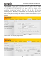
For example: If you want to disallow only PCs within the IP range
of 192.168.2.20~192.168.2.30 on your LAN to access only
websites containing “yahoo” from 8 : 00 to 18 : 00 during
working days: Monday- Fridaywhile not restricting other PCs,
then config same settings as shown on below screenshot on your
device:
Click “Save” to display page below:
64
Wireless N150 Mini AP/Router
Select “Allow” from the “Default” drop-down list and check the
“Enable URL Filter” feature.
10.4 Remote Web-based Management
The Remote Web-based Management feature allows users
to configure your device from Internet via a web browser.
65
Wireless N150 Mini AP/Router
Enable: Check or uncheck to enable or disable the remote
web-based management feature.
Port: Enter a port number for remote web-based
management.
IP Address: Enter the IP address of a PC on Internet
authorized to access and manage the device’s web-based
utility remotely.
Note:
If you enter 0.0.0.0 in the IP address box, then all PCs on
Internet can access your router’s Web-based utility to view or
change your settings remotely once you enable the remote
Web-based management feature.
For example: If you want to allow only a PC at the IP address of
218.88.93.33 to access your router’s web-based utility from
Internet via port: 8080, then config same settings shown on the
screenshot above on your device. And what this IP user needs
to do is to simply launch a browser and enter http:
//220.135.211.56:8080 (provided that the router’s WAN IP
address is 220.135.211.56).
66
Wireless N150 Mini AP/Router
Chapter 11 Routing Settings
11.1 Routing Table
This page displays the device core routing table which lists
destination IP, subnet mask, gateway, hop count and interface.
The principal task for a router is to look for an optimal transfer
path for each data packet passing through it, and transfer it to the
specified destination. So, it’s essential for the router to select an
optimal path, i.e. routing algorithm. To complete this work, the
router stores related data of various transfer paths, i.e.
establishing a routing table, for future route selection.
67
Wireless N150 Mini AP/Router
Chapter 12 Tools
12.1 Time Settings
This section assists you in setting the device’s system time;
you can either select to set the time and date manually or
automatically obtain the GMT time from Internet.
Sync with Internet time servers: Time and date will be
updated automatically from Internet.
Sync Interval: Determines a time length when device
periodically updates its time and date info from Internet.
The default is 2 hours.
Time Zone: Select your current time zone.
Copy Local Time: Click it to copy your PC’s time to the
device.
NOTE: The configured time information loses once the device is
powered off. But it obtains the GMT time automatically when you
68
Wireless N150 Mini AP/Router
reconnect it to the Internet. Features/functions based on time
(e.g. security settings) take effect only after Time and Date
settings are configured or updated automatically from Internet.
12.2 DDNS
Dynamic DNS or DDNS is a term used for the updating in real
time of Internet Domain Name System (DNS) name servers. We
use a numeric IP address allocated by Internet Service Provider
(ISP) to connect to Internet; the address may either be stable
("static"), or may change from one session on the Internet to the
next ("dynamic"). However, a numeric address is inconvenient to
remember; an address which changes unpredictably makes
connection impossible. The DDNS provider allocates a static
hostname to the user; whenever the user is allocated a new IP
address this is communicated to the DDNS provider by software
running on a computer or network device at that address; the
provider distributes the association between the hostname and
the address to the Internet's DNS servers so that they may resolve
DNS queries. Thus, uninterrupted access to devices and services
whose numeric IP address may change is maintained.
It is useful when you are hosting your own website, FTP server, or
other server behind the device.
Before you can use this feature, you need to sign up for
DDNS service with a DDNS service provider, like www.dyndns.org
or www.noip.com . If you do not want to use this feature, keep
the default Disable.
69
Wireless N150 Mini AP/Router
DDNS: Click Enable or Disable radio button to
enable/disable the DDNS feature.
Service Provider: Select your DDNS service provider from
the drop-down menu.
Username: Enter the DDNS username.1provided by your
DDNS service provider.
Password: Enter the DDNS password provided by your
DDNS service provider.
Domain Name: Enter the DDNS domain name distributed
by your DDNS service provider (optional).
For example: If you have registered a DDNS service in dyndns.org
and are given tenda, 123456, tenda.dyndns.info respectively as
username, password and domain name for a web server on your
PC at 192.168.2.10, then configure port settings on port range
forwarding interface under virtual server menu and enter this
information on the above DDNS interface. Others can access your
web server by simply entering http://tenda.dyndns.info in their
browser address bar.
70
Wireless N150 Mini AP/Router
Username
tenda
Password
Domain Name
123456
tenda.dyndns.info
12.3 Backup/Restore Settings
This section allows you to backup current settings or to restore
the previous settings configured on the device.
71
Wireless N150 Mini AP/Router
Backup Settings: Once you have configured the device the way
you want it, you can save these settings to a configuration file on
your local hard drive that can later be imported to your device in
case that the device is restored to factory default settings. To do
this, click the “Backup” button and specify a directory to save
settings on your local hardware.
Restore Settings: Click the "Browse" button to locate and select a
configuration file that is saved previously to your local hard drive.
72
Wireless N150 Mini AP/Router
And then click the "Restore" button to reset your device to
previous settings.
73
Wireless N150 Mini AP/Router
12.4 Restore to Factory Default Settings
To restore all settings to the device's factory default values, click
the "Restore to Factory Default” button:
Factory Default Settings:
User Name: admin
Password: admin
IP Address: 192.168.2.1
Subnet Mask: 255.255.255.0
Note: To activate your settings, you need to reboot the
device after you reset it.
12.5 Firmware Upgrade
Firmware upgrade is released periodically to improve the
functionality of your device and also to add new features. If you
run into a problem with a specific feature of the device, log on to
74
Wireless N150 Mini AP/Router
our website www.tendacn.com)to download the latest firmware
to update your device.
To update firmware, do as follows:
1. Click "Browse” to locate the firmware and "Upgrade” to
update.
2. Router will reboot automatically when upgrade
completes.
NOTE: Do not disconnect the device from your
management PC (the PC you use to configure the device)
or power off itduring the upgrade process; otherwise, it
may be permanently damaged. The device will restart
automatically when the upgrade process, which takes
several minutes to complete.
12.6 Reboot
This section allows you to reboot the device. New settings will be
activated after reboot. And WAN connection will be disconnected
75
Wireless N150 Mini AP/Router
during reboot.
To restart your device, click the “Reboot” button.
12.7 Change Password
This section allows you to change login password for accessing
device’s Web-based interface.
76
Wireless N150 Mini AP/Router
Old Password: Enter the old password.
New Password: Enter a new password.
Confirm New Password: Re-enter the new password for
confirmation.
Click “Save” to save your new password.
NOTE:For the sake of security, it is highly recommended that
youchange default login password.
12.8 Logs
The Syslog option allows you to view all events that occur
upon system startup.
Up to 150 entries of logs are recorded.
Refresh: Click this button to update the log.
Clear: Click this button to clear the log record.
77
Wireless N150 Mini AP/Router
Appendix 1:How to connect to an
encrypted wireless network
To connect to an encrypted wireless network, you must
provide a valid security key. Follow steps below (Below explains
how to connect to a WPA-encrypted wireless network in
Windows 7 OS):
1. Right click “Network”,select “Properties” and then left click
“Change adapter settings”. As seen below, Wireless Network
Connection displays Not Connected”.
2. Click the “Wireless Network Connection”, select
“Connect/Disconnect”. Below screen displays all available
networks.
78
Wireless N150 Mini AP/Router
3. Double click or select the SSID entitled “Tenda_××××××”
(where×××××× represents the last 6 characters in the device MAC
address) and click “Connect”. Enter the security key on appearing
window (Note that security key is case-sensitive. Here we assume
it is tendatenda) and click “OK”.
79
Wireless N150 Mini AP/Router
4. As seen below, display of “Connected” next to “Tenda_××××××”
indicates a successful connection.
80
Wireless N150 Mini AP/Router
Appendix 2: Glossary
Channel
A communication channel, also known as channel, refers either to
a physical transmission medium such as a wire or to a logical
connection over a multiplexed medium such as a radio channel. It
is used to transfer an information signal, such as a digital bit
stream, from one or more transmitters to one or more receivers.
If there are several APs coexisting in the same area, it is
recommended that you configure a different channel for each AP
to minimize the interference between neighboring APs. For
example, if 3 American- standard APs coexist in one area, you can
setup their channels respectively to 1, 6 and 11 to avoid mutual
interference.
SSID
Service set identifier (SSID) is used to identify a particular 802.11
wireless LAN. It is the name of a specific wireless network. To let
your wireless network adapter roam among different APs, you
must set all Aps’ SSID to the same name.
WEP
Wired Equivalent Privacy (WEP) is a security algorithm for IEEE
802.11 wireless networks with the intention to provide data
confidentiality comparable to that of a traditional wired
network .WEP, recognizable by the key of 10 or 26 hexadecimal
digits, is widely in use.
81
Wireless N150 Mini AP/Router
WEP uses the stream cipherRC4 for confidentiality,[5] and the
CRC-32 checksum for integrity.
Standard 64-bit WEP uses a 40-bit key (also known as WEP-40),
which is concatenated with a 24-bit initialization vector (IV) to
form the RC4 key. The extended 128-bit WEP protocol uses a
104-bit key size (WEP-104).
A 152-bit WEP is available from some vendors.
Static WEP encryption allows to include 4 WEP Keys while
dynamic WEP encryption changes WEP key dynamically.
WPA/WPA2
The WPA protocol implements the majority of the IEEE 802.11i
standard. It enhances data encryption through the Temporal Key
Integrity Protocol (TKIP) which is a 128-bit per-packet key,
meaning that it dynamically generates a new key for each packet.
WPA also includes a message integrity check feature to prevent
data packets from being hampered with. Only authorized network
users can access the wireless network.
The later WPA2 protocol features compliance with the full IEEE
802.11i standard and uses Advanced Encryption Standard (AES) in
addition to TKIP encryption protocol to guarantee better security
than that provided by WEP or WPA.
82
Wireless N150 Mini AP/Router
Appendix 3: FAQs
This section provides solutions to problems that may occur
during installation and operation of the device. Read the
following if you are running into problems. If you cannot find
solutions here, please go to our website www.tenda.cn (or
www.tendacn.com) or E-mail to [email protected] for help.
1. Q: I entered the device’s LAN IP address in the web browser
but cannot access the utility. What should I do?
A:1).Verify physical connectivity by checking if corresponding
port’s link LED lights up. If not, try a different cable. Note that an
illuminated light does NOT ALWAYS indicate successful
connectivity.
2).In Wireless Router Mode, you must use a wireless network
adapter to connect to the device, as the only Ethernet port works
as a WAN port for Internet connection; while in Wireless AP,
Universal Repeater Mode and Client Mode, you must specify an IP
address (192.168.2.2 ~ 192.168.2.253) on your PC to connect to
the device.
3).Click
“Start"
-“Run”,
enter
“cmd”
and
then“ping192.168.2.1”on appearing CLI to diagnose whether your
PC has connected to the device or not. If ping succeeds, then
check whether the Proxy Server feature is enabled on your
browser. If enabled, disable it immediately. In case that ping fails,
press and hold the "RESET" button on your device for 7 seconds
to restore factory default settings, and then run
“ping192.168.2.1” again.
83
Wireless N150 Mini AP/Router
4).Contact our technical support for help if the problem still
exists after you tried all the above.
2. Q: What should I do if I forget the login password to my
device (How do I reset my device)?
A: Reset your device by pressing the Reset button for over 7
seconds.
Note: All settings will be deleted and restored to factory defaults
once you pressed the Reset button.
3. Q: My computer shows an IP address conflict error after
having connected to the device. What should I do?
A:1) Check if there are other DHCP servers present in your LAN. If
there are other DHCP servers except your router, disable them
immediately.
2) The default IP address of the device is 192.168.2.1; make
sure this address is not used by another pc or device. In case that
two computers or devices share the same IP addresses, change
either to a different address.
4. Q: My computer can neither log in to the device nor access
internet, and there is a yellow triangle with an exclamation
mark shown in the network adapter icon on the right bottom
corner of my computer desktop; how am I supposed to deal
with it?
This problem occurs because your network card has not been
assigned with an IP address. If your computer is set to obtain an
84
Wireless N150 Mini AP/Router
IP address automatically, please ensure that the router's DHCP
function is enabled. DHCP can automatically assign an IP address
to your computer. If there is no DHCP, please set a static IP
address and fill in gateway and DNS, otherwise you cannot access
Internet.
5. Q: I cannot access Internet and send/receive emails; what
should I do?
A: This problem mainly happens to users using ADSL dialup or
dynamic IP internet connection types. In this case, go to “WAN
Settings” to change the MTU value from default 1492 to 1450 or
1400, etc.
6. Q: I am using Dynamic IP Internet connection type. How
should I config the device for Internet access?
A: Enter the device web utility, select “Dynamic IP” on Quick
Setup section and click “Save”.
B: If your ISP requires a specified MAC address for Internet
connection authentication, then go to MAC Clone and change the
device WAN MAC address to that MAC address and click “Save”.
7. Q: How do I share resources on my computer with users on
Internet through the device?
A: To let Internet users access internal servers on your LAN such
as e-mail server, Web, FTP, via the device, use the “Virtual
Server” feature. To do so, follow steps below:
Step 1: Create your internal server, make sure the LAN users can
85
Wireless N150 Mini AP/Router
access these servers and you need to know related service ports,
for example, Web server’s port is 80; FTP is 21; SMTP is 25 and
POP3 is 110.
Step 2: Click “Virtual Server” and select “Port Range Forwarding”
on the Router’s web interface.
Step 3: Input the start service port ID, for example, 80.
Step 4: Input the end service port ID, for example, 80.
Step 5: Input the internal server’s IP address. For example, if your
Web server’s IP address is 192.168. 2.10. Please input it.
Step 6: Select a communication protocol used by your internal
host: TCP, UDP or ICMP.
Step 7: Click “Save” to save such settings.
Below lists some well-known service ports for your reference.
Server
Protocol
Service Port ID
WEB Server
TCP
80
FTP Server
TCP
21
Telnet
TCP
23
NetMeeting
TCP
1503、1720
MSN
Messenger
TCP/UDP
FileSend:6891-6900(TCP)
Voice:1863、6901(TCP)
Voice:1863、5190(UDP)
PPTP VPN
Iphone5.0
SMTP
POP3
TCP
TCP
TCP
TCP
1723
22555
25
110
86
Wireless N150 Mini AP/Router
8. Q:I cannot access Internet in WISP Mode; what should I do?
A: Make sure your wireless network adapter is functioning
correctly on your PC and wireless signal is strong enough. If there
are too many available wireless networks, it is advisable to use
802.11 b/g mode for less interference.
B: Make sure you entered correct SSID and MAC address of the
link partner on the device. It is advisable to use the “Open scan”
option.
C: Make sure the device WAN IP and LAN IP addresses are not on
the same IP net segment. If so, change the device LAN IP.
D: Make sure antenna on the device is not detached.
If you still are unable to access Internet after you tried all the
above steps, contact our technical staff for help.
Add: Tenda Industrial Zone, No.34-1
ShilongRoad,ShiyanTown,BaoanDistrict,Shenzhen,China. 518108
General Inquiries
Tel: (86)755-27657180 Fax: (86)755-27657178
Email: [email protected]
Email: [email protected]
Skype: tendasz
MSN: [email protected]
Website: www.tendacn.com
SHENZHEN TENDA TECHNOLOGY CO.,LTD
www.tendacn.com
87
Wireless N150 Mini AP/Router
Safety Regulatory Statement
CE Mark Warning
This is a Class B product in a domestic environment, this product
may cause radio interference, in which case the user may be
required to take adequate measures. This device complies with
EU 1999/5/EC.
NOTE: (1) The manufacturer is not responsible for any radio or TV
interference caused by unauthorized modifications to this
equipment.(2) To avoid unnecessary radiation interference, it is
recommended to use a shielded RJ45 cable
FCC Statement
This device complies with Part 15 of the FCC Rules. Operation is
subject to the following two conditions: (1) This device may not
cause harmful interference, and (2) this device must accept any
interference received, including interference that may cause
undesired operation.
This equipment has been tested and found to comply with the
limits for a Class B digital device, pursuant to Part 15 of the FCC
Rules.
These limits are designed to provide reasonable
protection against harmful interference in a residential
88
Wireless N150 Mini AP/Router
installation. This equipment generates, uses and can radiate radio
frequency energy and, if not installed and used in accordance
with the instructions, may cause harmful interference to radio
communications.
However, there is no guarantee that
interference will not occur in a particular installation. If this
equipment does cause harmful interference to radio or television
reception, which can be determined by turning the equipment off
and on, the user is encouraged to try to correct the interference
by one of the following measures:
Reorient or relocate the receiving antenna.
Increase the separation between the equipment and
receiver.
Connect the equipment into an outlet on a circuit different
from that
to which the receiver is connected.
Consult the dealer or an experienced radio/TV technician
for help.
FCC Caution: Any changes or modifications not expressly
approved by the party responsible for compliance could void the
user's authority to operate this equipment.
This transmitter must not be co-located or operating in
conjunction with any other antenna or transmitter.
The manufacturer is not responsible for any radio or TV
interference caused by unauthorized modifications to this
equipment.
89
Wireless N150 Mini AP/Router
Radiation Exposure Statement
This equipment complies with FCC radiation exposure limits set
forth for an uncontrolled environment. This equipment should be
installed and operated with minimum distance 20cm between the
radiator & your body.
NOTE: (1) The manufacturer is not responsible for any radio or TV
interference caused by unauthorized modifications to this
equipment. (2) To avoid unnecessary radiation interference, it is
recommended to use a shielded RJ45 cable
NCC Notice
經型式認證合格之低功率射頻電機,非經許可,公司、商號
或使用者均不得擅自變更頻率、加大功率或變更設計之特性
及功能。
低功率射頻電機之作用不得影響飛航安全及幹擾合法通信;
經發現有幹擾現象時,應立即停用,並改善至無幹擾時方得
繼續使用。前項合法通信,指依電信規定作業之無線電信。
低功率射頻電機須忍受合法通信或工業、科學及醫療用電波
輻射性電機設備之幹擾。
90
Wireless N150 Mini AP/Router
Safety Instructions
1. Operation temperature range :0-40℃
2. For applicable power supplies see user manual
Adapter information:
Model: TEA09X-05120
(X=A or E or U or D)
Input: 100-240V, 50/60Hz, 0.3A
Output: DC5V 1.2A
3. USB output:5Vdc,0.5A
91