1
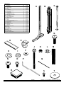
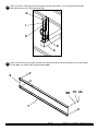
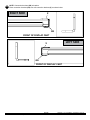
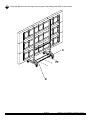
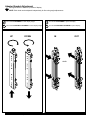
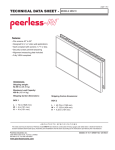
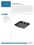
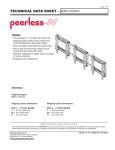
Installation and Assembly: 3 x 3 Cart
Model: DS-VWC655-3x3
Maximum Load Capacity 1000 Ibs (454 kg)
1 of 13
Visit the Peerless Web Site at www.peerlessmounts.com
ISSUED: 11-16-11 SHEET #: 125-9265-2 02-24-12
For customer care call 1-800-865-2112.
PARTS LIST
A
B
C
D
E
F
G
H
I
J
K
L
M
N
O
P
Q
R
S
T
U
V
W
X
Y
Z
AA
BB
CC
DD
EE
FF
GG
HH
Description
vertical support
adapter brackets
horizontal support
shelf
5" caster
1/4" flat washer
M8 x 25 mm phillips screw
5/16 flat washer
5/16 split washer
1/4-20 x 3.5" hex head screw
1/4-20 nylock nut
.38 OD x .06 lG nylon washer
18" mesh sleeve
M8 x 16 mm phillips screw
M6 x 12 mm phillips screw
4 mm allen wrench
cable tie
tube cap
M5 x 10 mm socket pin screw (not used)
#14 fender washer (not used)
lower front cover
lower back cover
upper cover
rail connection bracket
horizontal rail
side cover
M5 x 10 mm phillips screw
flat washer
lock washer
decorative screw
spacer
self-drilling screw
connection bracket
M6 x 16 mm phillips screw
Qty.
2
18
3
1
4
48
16
16
16
48
48
36
9
36
36
9
18
2
18
36
1
1
2
6
6
2
40
40
40
14
4
3
4
36
D
A
Part #
145-1543
145-1711
145-1382
145-1361
600-0026
540-9440
520-1031
540-9406
540-9405
520-1656
530-9413
590-2233
600-1014
520-9257
520-1128
560-9646
560-9711
590-1289
520-1164
540-1008
145-1505
145-1384
145-1450
145-1503
145-1447
145-1362
520-1233
540-9400
540-1035
520-2326
590-1136
520-1320
145-1504
520-9274
C
B
G
E
J
H
O
L
M
F
I
N
K
Q
P
R
S
2 of 13
Visit the Peerless Web Site at www.peerlessmounts.com
T
ISSUED: 11-16-11 SHEET #: 125-9265-2 02-24-12
For customer care call 1-800-865-2112.
U
V
X
W
Z
Y
AA
GG
BB
DD
EE
3 of 13
Visit the Peerless Web Site at www.peerlessmounts.com
CC
FF
ISSUED: 11-16-11 SHEET #: 125-9265-2 02-24-12
For customer care call 1-800-865-2112.
Assembling Cart
1
Attach two horizontal supports (C) to vertical support (A) using eight 1/4-20 x 3.5" hex head screws (J),
1/4" SAE washers (F) and 1/4-20 nylock nuts (K).
C
K
F
J
A
2
Attach horizontal supports (C) to second
vertical support (A) using eight 1/4-20 x 3.5" hex
head screws (J), 1/4" SAE washers (F) and 1/4-20
nylock nuts (K).
Attach horizontal support (C) to vertical supports (A)
using eight 1/4-20 x 3.5" hex head screws (J),
1/4" SAE washers (F) and 1/4-20 nylock nuts (K).
3
C
F
J
A
K
A
F
K
C
J
A
4 of 13
Visit the Peerless Web Site at www.peerlessmounts.com
ISSUED: 11-16-11 SHEET #: 125-9265-2 02-24-12
For customer care call 1-800-865-2112.
4
Attach four swivel casters (E) to vertical supports (A) using sixteen M8 x 25 mm pan phillips screws (G),
split washers (I) and 5/16" SAE flat washers (H).
G
I
H
E
A
5
Attach two rail brackets (Y) together using two rail connection brackets (X) with eight M5 x 10 mm pan phillips
screws (AA), lock washers (CC), and flat washers (BB).
X
BB CC AA
Y
5 of 13
Visit the Peerless Web Site at www.peerlessmounts.com
ISSUED: 11-16-11 SHEET #: 125-9265-2 02-24-12
For customer care call 1-800-865-2112.
6
Determine position of horizontal rails assemblies using the formula below.
1. Locate the position of the lower horizontal rail assemblies and attach to vertical supports (A).
2. Use display height to determine location of upper horizontal rail assemblies,
NOTE: Horizontal rail assemblies must be secured using twenty-four 1/4-20 x 3.5" hex head screws (J).
X = HEIGHT OF DISPLAY
X
HORIZONTAL RAIL ASSEMBLY
DISTANCE
EQUALS
display
HEIGHT
UPPER HORIZONTAL RAIL
display HEIGHT
LOWER HORIZONTAL RAIL
A
6 of 13
Visit the Peerless Web Site at www.peerlessmounts.com
ISSUED: 11-16-11 SHEET #: 125-9265-2 02-24-12
For customer care call 1-800-865-2112.
7
Attach three horizontal rails assemblies onto vertical supports (A) using twenty-four 1/4-20 x 3.5" hex head screws
(J), 1/4" SAE washers (F) and 1/4-20 nylock nuts (K) as shown in detail 2. Make sure that horizontal rail
assemblies are level then tighten all 1/4-20 x 3.5" hex head screws (J). Place two tube caps (R) into tops of vertical
supports (A) as shown in detail 2. NOTE: horizontal rails must be secured using twenty-four 1/4-20 x 3.5” hex head
screws (J).
K
Y
F
R
J
J
J
A
A
CABLE MANAGEMENT
8
DETAIL 2
Run display cables though top and bottom
openings in vertical supports (A) as shown.
NOTE: Display cables can be covered using
18" mesh sleeve (M) before securing.
Display cables can be secured to horizontal
rails assemblies using cable ties (Q) as needed
through slots in horizontal rails (Y).
Q
M
Y
TOP
OPENING
BOTTOM
OPENING
SLOT
A
Y
display cables
7 of 13
Visit the Peerless Web Site at www.peerlessmounts.com
ISSUED: 11-16-11 SHEET #: 125-9265-2 02-24-12
For customer care call 1-800-865-2112.
9
NOTE: Connection brackets (GG) orientation.
Place connection brackets (GG) onto rail connection brackets (X) as shown below.
X
RIGHT SIDE
GG
FRONT OF DISPLAY CART
LEFT SIDE
X
GG
FRONT OF DISPLAY CART
8 of 13
Visit the Peerless Web Site at www.peerlessmounts.com
ISSUED: 11-16-11 SHEET #: 125-9265-2 02-24-12
For customer care call 1-800-865-2112.
9-1 Attach connection brackets (GG) onto rail connection brackets (X) as shown below.
Secure one connection brackets (GG) with four M5 x 10 mm phillips screws (AA), lock washers (CC), and
flat washers (BB) as shown below. Repeat step for remaining three connection brackets (GG).
GG
BB
AA CC
X
RIGHT SIDE SHOWN ABOVE
9 of 13
Visit the Peerless Web Site at www.peerlessmounts.com
ISSUED: 11-16-11 SHEET #: 125-9265-2 02-24-12
For customer care call 1-800-865-2112.
10
Attach adapter brackets (B) to back of display using four M6 x 12 mm phillips screws (O) or M6 x 16 mm Phillips
screw (HH) with nylon shoulder washer (L), or four M8 x 15 mm phillips screws (N) as shown below.
Adapter Bracket Mounting Patterns
B
200 mm MIN
600 mm MAX
L
200 mm
display
400 mm
300 mm
PLP PLATE
N or O,HH
11
Hook display and adapter brackets (B) onto horizontal rail assemblies as shown below.
NOTE: Start with bottom display.
NOTE: Once display is located in desired position, tighten security screws as shown in detail 4.
display not shown for clarity
D
B
TIGHTEN
SEcurity
screw
DETAIL 4
10 of 13
Visit the Peerless Web Site at www.peerlessmounts.com
ISSUED: 11-16-11 SHEET #: 125-9265-2 02-24-12
For customer care call 1-800-865-2112.
12
Fasten shelf (D) onto horizontal support (C) using three self-drilling screws (FF) as shown below.
C
FF
D
11 of 13
Visit the Peerless Web Site at www.peerlessmounts.com
ISSUED: 11-16-11 SHEET #: 125-9265-2 02-24-12
For customer care call 1-800-865-2112.
Adapter Bracket Adjustment
13 Use legend below to determine position of display.
NOTE: Each knob can be adjusted independently for fine tuning angle adjustments.
Turn knobs CLOCKWISE to raise display height.
Turn knobs CLOCKWISE to push out display.
Turn knobs COUNTER-CLOCKWISE to lower display height.
Turn knob COUNTER-CLOCKWISE to pull in display.
UP
DOWN
IN
OUT
KNOB
12 of 13
Visit the Peerless Web Site at www.peerlessmounts.com
ISSUED: 11-16-11 SHEET #: 125-9265-2 02-24-12
For customer care call 1-800-865-2112.
Attaching Covers
14
NOTE: Position bottom front and back covers first
Position front bottom cover (U). Secure covers in place using four decorative screws (DD) as shown below.
Position back bottom cover (V). Secure covers in place using four decorative screws (DD) as shown below.
Position upper cover (W) on front of vertical supports (A). Secure covers in place using four decorative screws
(DD) as shown below. Position upper cover (W) on back of vertical supports (A). Secure covers in place using four
decorative screws (DD) as shown below.
DD
W
U
W
V
15
Z
BACK VIEW
A
Attach two retaining spacers (EE), and decorative screws (DD) to side
cover (Z) as shown to right. Attach side cover to vertical support (A) so
that it goes inside the lower front and back covers (U and V).
13 of 13
Visit the Peerless Web Site at www.peerlessmounts.com
EE
DD
ISSUED: 11-16-11 SHEET #: 125-9265-2 02-24-12
For customer care call 1-800-865-2112.