1
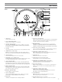
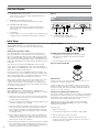
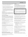
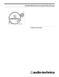
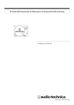
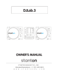
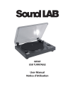
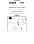
AT-LP1240-USB Professional DJ Direct-Drive Turntable (USB and Analog)
Installation and Operation
Professional DJ Direct-Drive Turntable
Safety instructions
1. Read these instructions.
2. Keep these instructions.
3. Heed all warnings.
4. Follow all instructions.
5. Do not use the apparatus near water.
6. Clean only with dry cloth.
7. Do not block any ventilation openings. Install in accordance with the manufacturer’s instructions.
8. Do not install near any heat sources such as radiators, heat registers, stoves, or other apparatus (including amplifiers) that produce heat.
9. Do not defeat the safety purpose of the polarized or grounding-type plug. A polarized plug has two blades with
one wider than the other. A grounding- type plug has two blades and a third grounding prong. The wide blade or
the third prong is provided for your safety. If the provided plug does not fit into your outlet, consult an electrician
for replacement of the obsolete outlet.
Includes:
Removable dust cover, Audacity recording software, USB cable & adapter cables
10. Protect the power cord from being walked on or pinched particularly at plugs, convenience receptacles, and the
point where they exit from the apparatus.
The AT-LP1240-USB Professional DJ Direct-Drive Turntable System features
the following:
• Direct drive high-torque multi-pole motor for demanding DJ use
• USB output – no special drivers required for direct connection to your computer
• Selectable 33/45/78 RPM speeds
• Selectable internal stereo phono pre-amplifier
• Dual start/stop controls
• Start and brake control adjustments
• Sliding pitch control with quartz speed lock
• Reverse operation
• S-shaped tone arm assembly with:
· Adjustable counterweight
· Anti-skate adjustment
· Tone arm height adjustment and lock
· Tone arm lift with hydraulic action and lift lever
· Tone arm rest with locking mechanism
• Dedicated ground lug for tone arm grounding
• Stroboscopic platter and speed accuracy indicator
• Damped cast aluminum record platter with low-resistance DJ-style slip mat
• Removable stylus target light
• 45-RPM adapter
• Adjustable feet for leveling
• Removable dust cover
11. Only use attachments/ accessories specified by the manufacturer.
12. Use only with a cart, stand, tripod, bracket or table specified by the manufacturer, or sold with
the apparatus. When a cart is used, use caution when moving the cart/apparatus combination
to avoid injury from tip-over.
13. Unplug this apparatus during lightning storms or when unused for long periods of time.
14. Refer all servicing to qualified service personnel. Servicing is required when the apparatus has been damaged
in any way, such as power-supply cord or plug is damaged, liquid has been spilled or objects have fallen into
the apparatus, the apparatus has been exposed to rain or moisture, does not operate normally, or has been
dropped. 15. When the mains plug or appliance coupler is used as the disconnect device, it shall remain readily operable.
16. Please keep the unit in a good ventilation environment.
WARNING
To reduce the risk of fire or electric shock, do not expose this apparatus to rain or moisture.
The apparatus shall not be exposed to dripping or splashing and that no objects filled with
liquids, such as vases, shall be placed on the apparatus.
CAUTION
RISK OF ELECTRIC SHOCK
DO NOT OPEN
Caution: To reduce the risk of electric shock, do not remove
any cover. No user-serviceable parts inside. Refer servicing
to qualified service personnel only.
The lightning flash with arrowhead symbol within the equilateral triangle is
intended to alert the use to the presence of un-insulated “dangerous voltage”
within the product’s enclosure that may be of sufficient magnitude to constitute
a risk of electric shock.
The exclamation point within the equilateral triangle is intended to alert the user
to the presence of important operation and maintenance (servicing) instructions
in the literature accompanying this appliance.
CAUTION
To prevent electric shock, do not use this polarized plug with an extension cord, receptacle or
other outlet unless the blades can be fully inserted to prevent blade exposure.
2
Introduction
Thank you for purchasing the AT-LP1240-USB Professional DJ Direct-Drive Turntable
(USB & Analog). This professional quality DJ turntable is designed primarily for DJ
use in nightclubs, touring and mobile applications. It can also be used by music
lovers to play their record collections at home. As an added benefit, the turntable
offers a USB output that allows direct connection to a computer for easy LP-todigital conversion. The turntable also features a built-in switchable phono/line
pre-amp that allows connection to a stereo system equipped with either a phono
or line-level input. Additional professional features for DJs include a sliding pitch
control, anti-skate control, start and brake control adjustments, reverse, and dual
start/stop controls.
To assure maximum satisfaction from this product, please read the information
and follow the instructions presented in this manual. Please keep the manual in an
accessible location for future reference.
Unpacking
Carefully unpack the turntable and verify that the following parts are included and
intact:
• Slip mat (above the dust cover)
• Dust cover (above the turntable)
• Platter (under the turntable)
• 45 RPM adapter (accessory section)
• Counterweight (accessory section)
• Headshell (accessory section)
• Power cord (accessory section)
• USB cable
• Dual RCA (female) to 1/8" (3.5 mm) mini-plug (male) stereo
adapter cable
• Dual RCA (female) to 1/8" (3.5 mm) mini-plug (female) stereo
adapter cable
• Dual RCA (male) cable with integrated ground wire
• Stylus target light (accessory section)
• Audacity software (CD)
IT IS RECOMMENDED THAT ALL PACKAGING MATERIALS BE SAVED FOR
POSSIBLE FUTURE STORAGE, MOVING OR SHIPPING.
Main Features
23
Figure 1
22
21
20
19
18
17
16
15
14
13
12
3
4
5
6
1. POWER DIAL
Controls power to the unit.
2. DUAL START/STOP BUTTONS
Engages and disengages the motor/platter.
3.
PLATTER SPEED BUTTONS
Select 33 or 45 RPM platter speed. (Note: 78 RPM is selected by
pressing both the 33 and 45 buttons simultaneously; both buttons
should be illuminated.)
7
8
9
10
11
13.HEADSHELL LOCKING RING
Rotate counter-clockwise (to the left) to draw the inserted headshell
firmly into its seated, locked position. Rotate the ring a full turn to
the right to permit removal of the headshell.
14.QUARTZ BUTTON
This button is used to turn the pitch function on and off. When
the Quartz is activated the platter will hold the RPMs at 0% pitch,
regardless of the pitch slider position and speed range control settings.
4. PLATTER
Cast aluminum platter mounts directly to center spindle/motor shaft.
15.PITCH ADJUST SLIDE CONTROL
Use in conjunction with pitch button to vary the platter’s rotational
speed. In the center detent position quartz lock is active.
5. STROBE DOTS (on platter edge)
Operate in conjunction with stroboscopic light located under the
power dial (1) to provide visual indication of accurate platter speeds.
16.TONE ARM ASSEMBLY HEIGHT ADJUST
Raises and lowers the entire tone arm assembly to allow the tone
arm to remain parallel to the record surface.
6. CENTER SPINDLE
Precision-machined platter mount on motor shaft.
17. TONE ARM LIFT
Elevates tone arm above record surface.
7. REMOVABLE STYLUS TARGET LIGHT
Provides illumination directed at the stylus position for easier cueing
in low light. Easily plugs into jack on top of turntable deck.
18.TONE ARM REST WITH LOCKING CLAMP
Locking clamp secures tone arm during transport.
8.
START CONTROL KNOB
Rotate the start control knob to increase or decrease platter start
time between 0.2 – 6.0 seconds. (Minimum setting is the quickest
start; maximum setting is the slowest start to reach selected speed.)
9.
BRAKE CONTROL KNOB
Rotate the brake control knob to increase or decrease platter brake
time between 0.2 – 6.0 seconds. (Minimum setting is the quickest
stop; maximum setting is slowest.)
19.TONE ARM LIFT CONTROL LEVER (“Cueing Lever”)
Controls action of tone arm lift. (Note: Lift mechanism is
hydraulically damped to slow tone arm descent.)
20.ANTI-SKATE CONTROL
Applies a small outward force to the tone arm, counteracting the
tendency of the tone arm to move inward toward the center of
the record.
10.REVERSE CONTROL KNOB
Controls platter’s rotational direction.
21.TONE ARM ASSEMBLY HEIGHT LOCK
(Hidden under counterweight in drawing.)
Locks the tone arm height setting. (Always fully unlock before
attempting to make a height adjustment.)
11. SELECT SPEED RANGE
Select +/- 10 or 20% speed range. (Note: +/-50% is selected by
pressing both the 10 and 20 buttons simultaneously.)
22.COUNTERWEIGHT
Balances the tone arm and provides adjustment for proper
downward tracking force on the stylus.
12.HEADSHELL
Standard, interchangeable stereo cartridge headshell.
23.45-RPM ADAPTER (Shown in receptacle)
Adapt 7" records with large center holes to fixed center spindle.
3
Rear View Diagram
24. PHONO/LINE OUTPUT RCA JACKS
Allows connection to a stereo system equipped with either a
phono- or line-level input
Figure 2
25. GROUND LUG (threaded thumb screw)
For connection to a pre-amp or ground lug of audio device.
26.
PRE-AMP SELECTOR SWITCH
Allows the internal stereo phono pre-amp to be bypassed
when the turntable is used with equipment having magnetic
phono inputs.
27. USB OUTPUT
Use this output to connect your turntable to the USB input of your
computer. Please see included software guide for instructions.
24
25
26
27
28
28. AC POWER CORD CONNECTOR
Use to connect the included power cord.
Initial Setup
Assembling the Turntable
The AT-LP1240-USB requires some assembly before first use.
IMPORTANT: Do not connect the AC power cord until assembly
is complete.
Setting the Pre-amp Selector Switch
For increased flexibility of use, this turntable has an internal stereo
phono pre-amplifier. The pre-amp selector switch located in the rear
panel of the turntable [See Figure 2, page 4, #26], selects the internal
stereo pre-amplifier (LINE), or bypasses the pre-amp (PHONO) for use
with systems having specialized magnetic phono input jacks. The audio
output cable’s Red RCA plug is the Right channel; the White plug is the
Left channel.
If the system you are using has a PHONO input, set the pre-amp
selector switch to the PHONO position and connect the turntable’s
output cables to the PHONO inputs on your system, observing Red for
Right channel and White for Left channel.
Figure 3 – Headshell
Assembling the Turntable Platter and Slip Mat
1. Carefully place the turntable platter on the center spindle,
making certain the platter is fully seated on the spindle.
[See Figure 4.]
2. Place the soft black slip mat on top of the platter.
Figure 4 – Platter and Slip Mat
If your system does not have a PHONO (magnetic phono) input, set
the pre-amp selector switch to LINE and connect the turntable’s output
cables to the Auxiliary (AUX) or other high-level inputs on your system,
observing Red for Right channel and White for Left channel.
When using the turntable with a computer sound card, set the switch
to LINE and connect the turntable to the audio line input on the
computer sound card. Note: An audio adapter (not included) may be
required to interface the two RCA jacks of the turntable output cable to
the computer sound card input.
Assembling the Tone Arm
Note: A standard stereo cartridge headshell is supplied with the
AT-LP1240-USB. To mount your cartridge (not included) to the headshell,
follow instructions included with your cartridge.
1. Remove the vinyl tie used to secure the tone arm during shipment.
Temporarily secure the tone arm in the tone arm rest with the locking clamp. [Figure 1, page 3, #18.]
2. Mount your cartridge (not included) to the supplied headshell, follow
instructions included with your cartridge.
3. Attach the headshell assembly by inserting it into the socket at the
front of the tone arm [See Figure 3.] (It’s good practice always to
hold a headshell assembly by the left and right edges of the headshell to reduce the possibility of damaging the stylus or disrupting
the cartridge wiring.)
4. While holding the headshell in position, rotate the headshell locking ring counter‑clockwise (to the left). As the ring turns, it pulls the
headshell into its seated position. (Rotate the ring a full turn to the
right to permit removal of the headshell.)
4
5. With its black dial toward the front, use a screwing motion to attach
the counterweight to the arm extending back from the tone arm
pivot [Figure 1, page 3, #22]; the counterweight will engage the spiral groove in the rear arm section and move forward.
The Dust Cover
The dust cover sits on top of the turntable without a hinge. It is not
intended to be used while playing records.
To place the dust cover on the turntable, carefully lower it onto the
turntable so that the Audio-Technica logo is facing the front of the unit.
To remove the dust cover from the turntable, carefully lift straight up
until the cover is clear of the unit.
Setting Tone Arm Balance and Tracking Force
To allow the cartridge to properly track in a record, the tone arm balance
and tracking force must be carefully set to the cartridge manufacturer’s
specifications. Failure to properly set up the tone arm assembly can
cause damage to the cartridge stylus and/or records.
(Note: Once the tone arm locking clamp has been released, take
extreme care not to damage the stylus. Do not allow it to drag or
scrape across the slip mat.)
Tone Arm Setup:
1. Raise the tone arm lift.
2. Set the anti-skate adjustment to “0”. [Figure 1, page 3, #20.]
3. Remove the protective stylus cover guard.
4. While gently holding the headshell to stabilize the tone arm,
release the tone arm locking clamp. At this point, the tone arm is
unbalanced and free to swing.
Initial Setup (continued)
5. While gently holding the headshell, carefully rotate the counterweight
until the tone arm is horizontally balanced and hovers freely just
above the platter without touching the platter surface.
6. Lock the tone arm back into the tone arm rest.
7.
While holding the counterweight steady, and without any rotation,
carefully rotate only the black stylus force gauge ring (which turns
independently of the counterweight) until the “0” on the gauge ring
lines up with the centerline marked along the top of the rear arm.
8.
Refer to the cartridge manufacturer’s specifications for
recommended tracking force. Rotate the entire counter-weight
counterclockwise without touching the black gauge ring, moving
the counterweight forward, until the desired value on gauge ring
lines up with the centerline marked on the rear arm. Refer to the
specifications section for tracking force value for the cartridge that
shipped with the turntable.
Setting Anti-skate
A small outward “anti-skating” force can be applied to the tone arm to
compensate for the “skating” force that pulls the arm toward the center
of the record. For best performance during normal turntable use, set
the anti-skate control knob [Figure 1, page 3, #20] to the same setting
as the tracking force dial. Refer to the specifications section for tracking
force value of your cartridge.
Setting Tone Arm Assembly Height
The tone arm assembly height adjustment allows for the tone arm to be
positioned parallel to the record surface, when using extra-tall cartridge
bodies, thick slip mats or thick records (i.e. old 78’s). To raise or lower
the tone arm assembly: First, loosen the height lock [Figure 1, page 3,
#21]; then rotate the height adjust dial [Figure 1, page 3, #16] located at
the base of the tone arm assembly. The scale is calibrated in millimeters
(mm). When finished, tighten the height lock to secure the adjustment.
How to set pitch
The Quartz button is used to turn the pitch function on and off. When
the Quartz is activated, the internal Quartz lock will hold the platter
at the precise rated speed (0% pitch), regardless of the pitch slider
position and speed range control settings.
Use the Pitch Adjust Slide Control in conjunction with the Pitch Buttons
to vary the platter’s rotational speed by as much as +/- 50%. In the
center detent position the Quartz lock is active.
How to measure pitch
Four rows of strobe dots on the platter edge are designed to measure
and verify the platter speed (pitch).
When the corresponding row of strobe dots appears to be stationary,
the turntable will be at the operating speed percentage indicated below.
If the dots appear to be moving to the right, the platter is moving
below rated speed; if they appear to be moving to the left, the platter is
moving above rated speed.
+7.2 % change in pitch when the dots in the top row are stationary
[point to top row of dots]
+3.3 % change in pitch when the dots in the second row are stationary
[point to second row of dots]
Connections
Connecting to Audio Source
Connect the included dual RCA (male) interconnect cable to the RCA
jacks on the back of the turntable. Connect the other end of the RCA
interconnect cable to the appropriate input jacks on your mixer, amplifier,
soundcard or other device based on the setting of the pre-amp selector
switch. (See Setting the Pre-Amp Selector Switch, page 4.) Firmly
connect the Red RCA plug to the right channel input and the White RCA
plug to the left channel input. Note: Adapter plugs might be required to
connect the turntable to computer sound cards and other devices.
Ground Wire
To isolate ground loops or low-level hum from your system, connect
the provided ground wire between the AT-LP1240-USB turntable and
your receiver, pre-amp, phono pre-amp, computer, or other connected
equipment.
Note: The ground wire is a small black wire terminated with a spade
lug; it is incorporated with the provided dual RCA (male) interconnect
cable. The ground wire connection point is the silver ground lug
(threaded thumb screw) on the back of the turntable to the right of the
RCA inputs.
Connecting to Computers with USB Input
Note: When using the USB cable, always set the AT-LP1240-USB
turntable’s Pre-amp Selector Switch to the “LINE” position. (Switch is
located on the back of the turntable.)
The USB cable (included) connects your AT-LP1240-USB turntable
to your computer without need for special drivers. Refer to included
software guide (also available online at www.audio-technica.com) before
connecting the turntable to your computer.
Connecting to Computers or Audio Devices with 3.5 mm Input
Note: When using either RCA adapter cable, always set the AT-LP1240USB turntable’s Pre-amp Selector Switch to the “LINE” position.
(Switch is located on the back of the turntable.)
The AT-LP1240-USB connects without adapters to devices equipped with
RCA connectors. For maximum flexibility, we have included two adapter
cables to fit other popular audio inputs.
The first of these adapter cables – dual RCA (female) to stereo 3.5
mm mini-plug (male) – is designed to fit most popular computer audio
inputs. It may also be used to connect the turntable’s RCA output to
other equipment, including:
• a stereo/boombox equipped with a 3.5 mm minijack
• input powered speakers equipped with a
3.5 mm minijack
• input a mixer or PA system equipped with a
3.5 mm minijack
The second included adapter cable – dual RCA (female) to stereo 3.5
mm mini-plug (female) – permits connection of the turntable output to
amplified speakers or similar devices. The 3.5 mm stereo minijack on
the cable adapter accepts stereo mini-plugs.
To use either adapter cable, connect the turntable’s red and white RCA
plugs to the cable adapter’s RCA jacks.
-3.3 % change in pitch when the dots in the bottom row are stationary
[point to bottom row of dots]
Note: If connection is desired to a mono amplifier/speaker, make
certain to use a stereo-to-mono adapter, available from your dealer or
an electronic parts store. Inserting a mono plug in the stereo jack will
disable one of the stereo channels. Other adapter cable configurations
will be available from dealers and parts stores for connecting to devices
needing different terminations.
Adjusting Platter Start Speed and Brake Speed
Rotate the Start control knob to increase or decrease platter start time
between 0.2 – 6.0 seconds. (Minimum setting is the quickest start;
maximum setting is the slowest start to reach selected speed.)
Connecting AC Power Cord
Finally, after all other connections are made, attach the included AC
power cord to the turntable; note that the small connector only goes in
one way. Then connect the power cord’s plug to a convenient AC outlet.
0 % change in pitch (normal speed) when the dots in the third row are
stationary [point to third row of dots]
Rotate the Brake control knob to increase or decrease platter brake
time between 0.2 – 6.0 seconds. (Minimum setting is the quickest stop;
maximum setting is slowest.)
5
Operation
For best results, do not install or operate this unit near conditions of
heat, moisture, dust, or heavy vibrations. (Note: Bright fluorescent lights
may affect the visibility of the speed-indicating strobe dots. If this is a
problem, simply cover the area with your hand, an album cover, etc.)
Preparing to Play
1. If using in USB or Line mode, the pre-amp selector switch must
be in the Line position.
2.
If there is a stylus guard on your stylus assembly, remove it;
unlock the tone arm rest if it is locked.
3.
Turn the power dial to the ON position. The speed selector and
strobe illuminator will light up.
4.
If desired, plug in the stylus target light for illumination of the
stylus tip position on the record.
5.
Place a record on the slip mat, lining up its center hole with the
center spindle. For 45 RPM records, place the 45 RPM adapter on
the center spindle before placing the record on the platter.
6.
Set the platter rotation speed (33/45/78) to match that of the
record. (Note: To set the platter speed for 78 RPM, push both the
33 and 45 RPM buttons simultaneously.)
Playing the Record
1. Press the start/stop button; the platter begins to rotate.
2.
Raise the tone arm by lifting the tone arm lift control lever to the
UP position.
3.
Position the tone arm over the desired location (groove) on
the record.
4.
Lower the tone arm by moving the tone arm lift control lever to
the DOWN position. The tone arm descends slowly onto the
record and play begins.
– or –
Use the finger-lift on the headshell assembly to position the tone
arm over the desired location on the record. Carefully lower the
tone arm to the record surface.
Reverse Play
1. If desired, press the reverse button to reverse the rotation of the
platter. The reverse button will illuminate.
Suspending or Ending Play
1. To suspend play, lift the tone arm with the cueing lever.
2.
When play is finished, raise the cueing lever, move the tone arm
to the rest position and secure the tone arm with the tone arm
locking clamp.
3.
If using the stylus target light, turn it off by removing it from
the jack.
4.
Press the start/stop button to apply the brake and stop the
platter rotation.
5.
Turn the power dial to the OFF position.
5
Turntable is picking up excessive vibrations from floor, walls, or
nearby speakers. Reduce vibrations or place turntable on sturdy/
solid surface.
Troubleshooting
Turntable operates but emits no sound or not enough sound.
1. The stylus guard is still in place. Remove the stylus guard.
2.
The tone arm is in the lift position. Lower the tone arm.
3.
Mixer/amplifier (system) controls are set incorrectly: wrong input
selected, tape monitor on, speakers switched off, etc. Verify
proper control settings.
4.
Stylus is broken or missing. Check the stylus assembly and
replace if necessary.
5.
The stylus assembly may not be fully seated in the cartridge body.
Check the cartridge and adjust if necessary.
6. The turntable pre-amp selector switch is set in the wrong position.
Verify that it is set for proper output to match mixer/amplifier input.
- No sound/very weak sound: Phono setting into an
Aux/Line input.
- Very loud/distorted sound: Line setting into a Phono input.
Note: If using in USB or line mode, the pre-amp selector switch must
be in the Line position.
Turntable operates but stylus “skips” across record.
1. The stylus guard is still in place. Remove the stylus guard.
6
2.
The tracking force is set too light. Set tracking force per cartridge
manufacturer’s recommendation.
3.
The tracking force is set too heavy (stylus assembly is bottoming
out on record). Set tracking force per cartridge manufacturer’s
recommendation.
4.
The anti-skate control is set improperly. Verify anti-skate is set for
same value as cartridge tracking force.
Record sounds too fast or too slow.
1. Turntable is set for wrong speed. Make proper speed selection for
record type being played with platter speed buttons.
2.
Variable pitch is engaged. Depress Quartz button or return pitch
adjust slider to center detent position to engage quartz lock.
Moving pitch adjust slider produces no effect.
1. If the LED next to the pitch adjust slider center detent position
remains blue when the slider is moved, quartz lock is engaged.
Depress the quartz button to disengage the quartz lock and
activate variable pitch. The LED should turn off.
Strobe dots are difficult to see and/or stylus illuminator is very dim.
1. Excessively bright or fluorescent light interferes with strobe
indicator. Hold hand, record jacket, etc. over strobe indicator to
shield it from bright light.
Troubleshooting (continued)
• When lifting or replacing the turntable cover, handle it gently.
•
Do not touch the stylus tip with your fingers; avoid bumping
the stylus on the turntable mat or a record’s edge.
•
Clean the stylus tip frequently, following the stylus manufacturer’s cleaning instructions.
•
If you use a stylus cleaning fluid, use it sparingly, while referring to the manufacturer’s cleaning instructions.
•
Wipe the dust cover and turntable housing gently with a soft
cloth. Use a slightly damp cloth to clean the turntable and dust
cover.
•
Never apply harsh chemicals or solvents to any part of the
turntable system.
•
Prior to moving the turntable, always unplug it from the AC
outlet and lock the tone arm on the tone arm rest.
Specifications†
Type
Motor
Drive method
Speeds
Turntable platter
Starting torque
Braking system
Wow and flutter
Signal-to-noise ratio
Output level
Pre-amp “PHONO”
Pre-amp “LINE”
RIAA Tone arm type
Effective arm length
Overhang
Height of tonearm adjustment range
Tracking error angle
Applicable cartridge weight
Without headshell
With headshell
Anti-skating range
3-Speed, fully manual operation
16-pole, 3-phase, brushless DC motor
Direct drive
33-1/3 RPM, 45 RPM, 78 RPM
332 mm dia. die-cast aluminum
>4.5 kgf.cm
Electronic brake
< 0.1% WRMS (JIS WTD) with 33 RPM
> 55 dB (DIN-B)
2.5 mV nominal at 1 kHz, 5 cm/sec
(HP-4005)
150 mV nominal at 1 kHz, 5 cm/sec
(HP-4005)
20-20kHz, +1/-3dB (In: 1.5mV 1kHz)
Static balanced S-shaped tone arm with
detachable headshell
230 mm
15 mm
0-6 mm
USB function
A/D, D/A
Computer interface
Power supply
requirements
Power consumption
Dimensions
Weight
Accessories included
†
16 bit 44.1 kHz or 48 kHz USB selectable
USB 1.1 Compliant Windows XP or
above or MAC OSX or above
120V AC, 60 Hz
13W
450.0 mm (17.72") W x 353.0 mm
(13.90") D x 166.5 mm (6.56") H
12.5 kg (27.6 lbs.)
Slip mat; dust cover; platter; 45 RPM
adapter; counterweight; headshell;
power cord; USB cable; dual RCA
(female) to 1/8" (3.5 mm) mini-plug (male)
stereo adapter cable; dual RCA (female)
to 1/8" (3.5 mm) mini-plug (female) stereo
adapter cable; dual RCA (male) cable
with integrated ground wire; stylus
target light; Audacity software (CD)
Specifications are subject to change without notice.
Less than 3 degrees
3.5 - 8.5 g
13 - 18 g
0-3 g
7
Register your product online at www.audio-technica.com
U.S. One-Year Limited End-User Warranty
Select Audio-Technica brand products purchased in the U.S.A. from an authorized
Audio-Technica (A.T.U.S.) dealer are warranted for one year from date of purchase
by A.T.U.S. to be free of defects in materials and workmanship. In event of a defect,
End-User’s exclusive remedy is at A.T.U.S.’ election, the cost of repair, refund of
the purchase price in the form of credit or cash, or replacement of the product.
The product must be delivered to A.T.U.S. or an Authorized Service Center, prepaid,
together with the sales slip or other proof of purchase date. This warranty excludes
defects due to normal wear, abuse, shipping damage, or failure to use product in
accordance with instructions. This warranty is void in the event of unauthorized
repair or modification, or removal or defacing of the product labeling.
For U.S. service return instructions and procedure please go to:
www.audio-technica.com/returninstructions.
A.T.U.S.’ warranty is to the End User only. Except for A.T.U.S.’ said express warranty,
A.T.U.S. MAKES NO WARRANTIES, EXPRESS OR IMPLIED, WITH RESPECT
TO THE PRODUCTS. A.T.U.S. SPECIFICALLY MAKES NO WARRANTY OF
MERCHANTABILITY OR FITNESS FOR A PARTICULAR PURPOSE.
Except to the extent precluded by applicable state law, A.T.U.S. IS NOT LIABLE
FOR CONSEQUENTIAL, INCIDENTAL, DIRECT OR SPECIAL DAMAGES
ARISING, DIRECTLY OR INDIRECTLY, IN RESPECT OF SUCH PRODUCTS OR
USE OR FAILURE THEREOF, WHETHER BASED ON BREACH OF WARRANTY,
NEGLIGENCE, STRICT LIABILITY, TORT OR OTHERWISE.
This warranty gives you specific legal rights, and you may have other rights which
vary from state to state.
Outside the U.S.A., please contact your local dealer for warranty details.
Audio -Technica U.S., Inc.
1221 Commerce Drive, Stow, Ohio 44224 (330) 686-2600
audio-technica.com
©2012 Audio -Technica U.S., Inc.
P52369