1
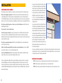
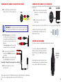
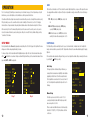
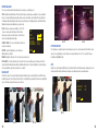
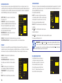
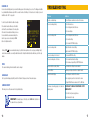
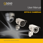
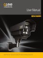
User Manual
QD6506BH
High-Resolution Security Camera with Heat-Circulating Blower Fan
1
Thank You for Choosing a Q-See Product!
About this Manual
All of our products are backed by a conditional service warranty covering all hardware for 12 months from the date of purchase.
Additionally, our products also come with a free exchange policy that covers all manufacturing defects for one month from the date of
purchase. Permanent upgrading service is provided for the software and is available at www.Q-See.com.
This manual is written for the Q-See’s QD6506BH high-resolution camera with heat-circulating blower fan and using Sony’s EFFIO-E
image processor. This manual was accurate at the time it was completed. However, because of our ongoing effort to constantly
improve our products, additional features and functions may have been added since that time and on-screen displays may change.
We encourage you to visit our website at www.Q-See.com to check for the latest product announcements. You can also find technical
details for your specific camera on its product page at our site.
Be certain to make the most of your warranty by completing the registration form online. In addition to warranty and technical support
benefits, you’ll receive notifications of product updates along with free downloadable firmware updates for your DVR. Register today
at www.Q-See.com!
Throughout the manual we have highlighted warnings and other important information that will assist you in operating your new
system in a safe and trouble-free manner. Please take the time to read and follow all instructions and pay attention to alerts as
shown below:
Please see the back of this manual for exclusions.
IMPORTANT! Red boxes with this icon indicate warnings. To prevent possible injury or
damage to the product, read all warnings before use.
NOTE! Text in blue boxes with the Information icon offer additional guidance and explanations
about how to make the most out of your system.
© 2011 Q-See. Reproduction in whole or in part without written permission is prohibited. All rights reserved. This manual and
software and hardware described herein, in whole or in part, may not be reproduced, translated, or reduced to any machine-readable
form without prior written approval.
Trademarks: All brand names and products are trademarks or registered trademarks of their respective owners.
Q-See is a registered trademark of DPS, Inc.
Disclaimer: The information in this document is subject to change without notice. The manufacturer makes no representations or
warranties, either express or implied, of any kind with respect to completeness of its contents.
Manufacturer shall not be liable for any damages whatsoever from misuse of this product.
2
DMQD6506BH001 Rev. 1.0 8/25/12
3
TABLE OF CONTENTS
INTRODUCTION
INTRODUCTION5
INSTALLATION6
Positioning Your Camera
6
Mounting the Camera
7
Connecting the Camera to a Security DVR System
8
Connecting the camera to a TV or Monitor
9
Controlling Your Camera
9
OPERATION10
Setup Menu
10
Lens11
Shutter/AGC11
White Balance
12
Backlight12
Picture Adjust
13
ATR13
Motion Detection
14
Privacy14
Day/Night Mode
15
NR (Noise Reduction)
15
Camera ID
16
SYNC16
Language16
Camera Reset 16
TROUBLESHOOTING17
Q-SEE PRODUCT WARRANTY
4
18
For your safety
To prevent damage to your Q-See product or injury to yourself or to others, read and understand the following safety precautions in
their entirety before installing or using this equipment.
WARNING! ELECTRIC SHOCK RISK!
nCare should be taken during transportation, storage and installation of this camera to avoid rough handling, dropping, or other
abuse in order to prevent damage to the optics or components inside the camera.
nCamera should be installed in accordance with electrical standards including keeping the camera and cable away from high
voltage, using a surge protector and using only the rated power supply.
nDo not use strong or abrasive cleaners on camera body or lens. Use a damp cloth for cleaning the housing and a lens cloth for the
optics.
nDo not attempt to disassemble the camera. Only authorized, trained technicians should service this camera.
nCameras should not be immersed in water and should be mounted in a sheltered location. Do not point camera directly at the sun
or other strong light source.
Product Features
These cameras offer the following features:
nUltra high definition video using 1/3” Sony HAD CCD II sensors coupled with the latest Sony Effio-E digital signal processors to
produce 650 TV lines of resolution.
nLow light and infrared operation. The camera takes advantage of even low levels of ambient lighting to produce images with color.
nAutomatically switches to infrared (black and white) mode when no light is detected.
nInfrared illumination in total darkness up to 60 feet.
nLow light vision capability utilizes ambient light to view up to 120 feet at night.
nBuilt-in motion detection. The camera can be set to respond to motion even without being connected to a DVR.
nOn-Screen Display (OSD) allows you to configure the camera using the built-in thumbstick when connected to a monitor.
nMultiple language support; English, Spanish, French, Russian, Portuguese, German, Chinese and Japanese.
nCustomizable settings: WDR (wide dynamic range), White Balance, Contrast, Shutter Speed, Sharpness, etc.
nHighlight Compensation. Excessive light, such as headlights, can be masked if desired.
nHigh-speed Moving Object Capture function allows clear images of objects moving at high speed.
5
INSTALLATION
POSITIONING YOUR CAMERA
When installing your camera, it is important to select a proper site not only for field of view, but for other considerations as well:
Distance from viewing/recording device. The further the camera is from the DVR or monitor, the higher the chances
of signal degradation. Typical 75Ω Video Cable provides acceptable signal at distances up to 200’ (30m). At greater distances,
UL-Listed shielded RG59 should be used. The camera’s power supply should be located as near to the camera as possible when the
distance exceeds 200’ as the power level will drop over extended distances resulting in a decrease in video quality and IR LED range.
Do not place near high voltage wires or other sources of electrical interference. Electrical interference will
degrade the quality of the signal.
Place camera out of reach to avoid damage.
Avoid direct exposure to weather. Do not place the camera where rain or snow will hit the lens directly nor should the
camera be placed so that the sun or bright light shines directly into the lens. Indoor cameras should never be placed outside.
Weatherproof cameras will not work when submerged. Ensure that all power and video connections are not directly exposed to water
and are protected from the elements.
Do not place camera behind a window. The IR LEDs act like a flashlight and will create a reflection that will obscure
events on the other side of the glass.
Light levels should be approximately the same between camera and target area. A camera in a brightly-lit
area looking into a shaded area, or vice versa, will produce inadequate results.
Avoid areas with high vibration. Vibrations from heavy equipment or machinery adjacent to the wall that the camera is
mounted on will cause the camera to shake and the resulting video will also be shaky.
The above are guidelines and the optimal location for your camera will depend on your unique circumstances. As a general rule,
the locations highlighted in green in the picture on the following page indicate the best locations to mount your camera. Both
locations are sheltered from rain or snow and offer good sight lines to allow your camera to monitor a wide area. Your camera has
a wall mount with limited flexibility, making the lower area the ideal position. However, your individual circumstances may require an
alternate method of mounting.
6
Because your camera is weatherproof and contains an internal
fan to circulate heat generated by the power supply through the
housing, it requires less protection than most other weatherproof
cameras as well as those which are merely weather-resistant.
It can be placed in more exposed locations if needed. Keep in
mind that this camera is designed to operate between -22°F
to 140°F (-30°C to 60°) with a relative humidity of up to 95%)
and consider wind chill and other environmental factors when
selecting your location.
Your camera has an Ingress Protection (IP) rating of IP66, which
is the highest level currently available. This rating measures the
level of protection against environmental factors such as dust
and moisture getting into the inner workings of the camera. The
internal fan will circulate air within the camera housing and will
prevent the lens from fogging up internally. However, the internal
heat of the camera will not be enough to melt ice or evaporate
moisture on the outside of the camera body. Care should be
taken, therefore, that the camera will not be positioned in a way
that moisture will accumulate on the outside of the lens, or that
the lens will be blocked by icicles.
Please also keep in mind that your camera weighs 3.2 pounds (1455 grams) and the mounting surface should be strong enough to
support the weight of the camera. It is not recommended to attach this camera to drywall, but rather to use screws long enough to
securely fasten the camera to the structural wood frame behind it.
MOUNTING THE CAMERA
STEP 1. At the desired location, use the mounting bracket to mark the position for the holses for the mounting screws
STEP 2. Drill the mounting holes, along with a larger hole to pass the cable through if desired.
STEP 3. Mount the camera using the proper hardware. We have included fasteners for wood, masonry and stucco surfaces.
7
CONNECTING THE CAMERA TO A SECURITY DVR SYSTEM
STEP 1. Connect the BNC and power leads from the camera to the
matching connectors on one end of the power and video cable.
CAMERA
CONNECTING THE CAMERA TO A TV OR MONITOR
A single camera can be connected directly to a monitor or TV with an RCA input using the included cable and a separately available
adapter if needed.
CAMERA
TV or MONITOR
STEP 1. Connect the camera to the cable and power supply as
described in Steps 1, 2 and 5 above before connecting it to
your video display.
STEP 2. Connect the camera to the “Video In” port on the
monitor or television.
IMPORTANT! When connecting the power and video cable between the camera and the DVR, the
“male” power end (red plug in the illlustration) connects to the matching power lead on the camera.
STEP 2. For multi-camera packs, connect the power lead on the
other end of the cable to the plug from the power splitter. Or, if
your package includes a power distribution panel, connect the
power lead to one of the power jacks on the panel. Proceed to
Step 4, below.
For single camera packages, connect the power lead to the
power adapter itself. In this case, you may skip to Step 4.
STEP 3. Connect the power lead on the power splitter to the
camera power adapter. DO NOT plug the adapter into an
outlet at this time.
STEP 4. Connect the BNC connector on the other end of the video/
power cable to a Video In port on the back of the DVR.
Repeat Steps 1 through 4 for all cameras before continuing.
STEP 5. Plug the power adapter into a surge protector* or
turn on the power panel.
*When selecting a surge protector, it is STRONGLY recommended to use one that is UL-1449 rated, for a clamping voltage
of 330 or lower, a Joule rating of at least 400 and a response time of 10 nanoseconds or less.
8
For Television: You may need to tune or select the correct INPUT (i.e.; A/V, L1, L2, Source) Consult your television’s manual for details.
Depending on your TV or monitor, you may need to use a BNC-toRCA adapter (not included) to connect the BNC connector on the
video/power cable to your screen.
CONTROLLING YOUR CAMERA
The camera’s on-screen menu is accessed by the multifunction button attached to the camera cable.
To access the on screen display, press the multifunction button. This
will bring up the menu on your system’s monitor or other attached
display. This button also acts as the “Enter” button when setting your
parameters.
Cable-Mounted
Multi-Function
Button
Navigate through the menu using the directional controls. The cablemounted multi-function button acts as a miniature joystick allowing you
to move up, down, left or right through the menu and submenus.
9
LENS
OPERATION
The On Screen Display (OSD) built into your camera allows you to control almost every aspect of how it captures images. Using the
built-in menus, you can control brightness, contrast, white balance, shutter speed and other functions.
It should be noted that these settings must be made at the camera itself and they cannot be set remotely. When used with a security
DVR system, what you see on the screen will be what is recorded - including the OSD menu. In fact, use of the OSD can trigger
motion detection so it may be advisable to temporarily disconnect/disable alarms or notifications when working in the OSD menu.
When saved using the “Save All” command, settings will be stored on the camera even in the event of power loss. Once power is
restored, the camera will continue to operate according to your settings. You can revert to the factory default settings by selecting
“Camera Reset” in the menu.
This turns the auto iris feature on or off. The iris controls the amount of light entering the lens, or exposure. This requires the camera
to be equipped with an automatic lens. At present, this option is only available on box-type cameras. With such a lens attached, you
can select;
AUTO IRIS
TYPE - DC (direct current) or VIDEO (video control) of the
iris.
MODE - AUTO (automatically adjusts), OPEN (always
opened) or CLOSE (always closed).
TYPEDC
MODE
AUTO
SPEED
080
SPEED - When the mode is set to AUTO, this controls the
sensitivity of the lens with a value ranging from 0 to 255.
RETURN SETUP MENU
SHUTTER/AGC
Pressing the multi-function or Menu button (depending on model) will open the OSD to the first page of the Setup Menu. The menu
will appear over the video image being delivered by the camera.
The Shutter setting controls how much light is used to “expose” each frame while AGC, or Automatic Gain Control “amplifies” the
image to show more detail. As a general rule, the AUTO setting will be sufficient as the camera will automatically adjust to changing
light levels.
To change a setting, scroll to the desired item until it is highlighted and press right or left to select the desired value. Menu options
with a “ ” indicate that there is a submenu. Clicking on an item with that option will take you to the submenu. Move between the two
pages using NEXT or BACK as appropriate.
SETUP MENU
SETUP MENU
Auto Setup
LENSMANUAL
SHUTTER/AGCAUTO
WHITE BAL
ATW
BACKLIGHTOFF
PICT ADJUST
ATR
OFF
MOTION DET OFF
NEXT
EXIT SAVE ALL
PRIVACYOFF
DAY/NIGHT
AUTO
NR
CAMERA ID
OFF
SYNCINT
LANGUAGEENGLISH
CAMERA RESET
BACK
EXIT SAVE ALL
The image at right shows the default settings. In this menu, you
can adjust how the camera behaves in brightly lit or dark situations
by adjusting the Shutter from 0-255 with zero being the darkest.
The AGC amplification can be turned off or it can be set from x0.25
to x1.00 but the higher the amplification, the higher the “noise” in
the image.
Page 1
10
In the rare situation where automatic settings aren’t ideal, you can chose to adjust the automatic settings or manually set the values
by selecting AUTO or MANUAL respectively.
Page 2
AUTO SETUP
HIGH LUMINANCE
MODE
SHUT
BRIGHTNESS
024
LOW LUMINANCE
MODE AGC
BRIGHTNESSX0.50
RETURN Manual Setup
The shutter speed can be set from 1/60 second to 1/10,000
second going from lighter to darker with the higher speed. AGC’s
value can range from 6.00 to 44.8.
If there is a video monitor within the camera’s field of view, setting
the shutter to 1/100 (NTSC) or 1/120 (PAL) will reduce the flicker
on the screen.
MANUAL SETUP
MODE
SHUT+AGC
SHUTTER1/60
AGC
6.00
RETURN 11
WHITE BALANCE
There are seven modes available for determining how your camera processes and displays color:
ATW - Automatic Tracking White Balance. This is the default the camera constantly analyses and adjusts to create a neutral white
balance. Colors may be slightly underexposed but generally accurate. Several settings can be modified, but the most significant is
the Environment setting which adjusts the white balance based on the light source. Daylight generally has a bluish tint while indoor
lighting will tend towards yellow (light bulbs) or green (fluorescent).
PUSH - Working in a narrower band of lighting - 2300K-10000K
ATW
- it may over-compensate the white balance if the field of view
includes a large, single-colored object. However, it is the preferred
SPEED
239
DELAY CNT
016
mode for areas illuminated by halogen lights.
ATW FRAME
X1.00
USER1 & USER2 - These are user defined modes The blue and
ENVIRONMENTINDOOR
red gains can be adjusted.
PICTURE ADJUST
ANTI CR - (Anti Color Rolling) Reduces color rolling in areas
RETURN illuminated by fluorescent lights.
MANUAL - Adjust the setting from 0-255 to best suit your personal preference.
This setting allows you to adjust the way the picture is displayed on your screen. Changes made will not affect what the camera
captures. You can adjust brightness, contrast, sharpness, hue and gain with values from 0-255. You can also flip the image
horizontally using the Mirror setting.
PUSH LOCK - Locks in the white balance at its current level. This can be set by holding a piece of white paper in front of the
camera. Pushing the multi-function button will then establish the white balance. Use this when the lighting is constantly changing or
the area surrounding the object under observation is over- or under-lit
ATR
BACKLIGHT
HLC Off
HLC On
Adaptive Tone-curve Reproduction (ATR) attempts to show details in both the well-lit and shaded areas simultaneously for a more
complete view. When enabled, both luminance and contrast can be adjusted to produce a more balanced image.
This allows the camera to compensate for lighting coming from behind the subject as well as bright light sources within the image.
Backlight compensation can be left turned off, turned on (BLC) or set to Highlight Compensation (HLC) which masks overly bright light
sources in the image, making certain features easier to make out.
ATR
LUMINANCE
MID
CONTRASTMID
RETURN ATR On
BLC Off
12
BLC On
13
MOTION DETECTION
DAY/NIGHT MODE
Unlike most security cameras, your camera is capable of detecting motion by itself. If you are connecting your camera to a Q-See
security DVR, you will not need to enable this feature as the DVR itself has motion detection capabilities. Enabling motion detection on
the camera while connected to a security DVR can produce adverse results by obscuring the recorded video or generating artifacts
which the DVR will interpret as motion causing it to record unnecessarily.
This allows you to set the camera to switch automatically from day to night mode (the default) or to permanently set it to Color or B/W
operation. Please note that even when the camera is set to Color mode, it will switch to black and white night vision when there is no
longer enough ambient light to support color video.
DAY/NIGHT
You can adjust the automatic settings.
DETECT SENSE - The camera’s level of sensitivity to motion.
The value range is 0-127.
BLOCK DISP - If this is turned on, the camera will generate
pixelated blocks to highlight motion within its view. It should be noted
that if you have this enabled while the camera is connected to a
security DVR, the DVR will record the blocks as part of the video and
these cannot be removed from the recording.
MONITOR AREA - When enabled, you may select up to four
areas where motion will be detected.
MOTION DETECT
DETECT SENSE
BLOCK DISP OFF
MONITOR AREAOFF
AREA SEL
1/4
TOP
BOTTOM
LEFT
RIGHT
RETURN 111
000
000
000
000
This allows you to set up areas within the camera’s view that will be blocked from observation. This may be the location of a
combination lock, keypad or other area that requires privacy. Like Motion Detection above, use of this feature is not recommended
when the camera is connected to a security DVR as it will create artifacts on the video recording which cannot be removed.
RETURN DAY NIGHT - Sets the threshold level for when the camera
should switch to night mode.
IMPORTANT! The DAY NIGHT and NIGHT DAY operations should be tested during installation. Block the lens
for a few seconds to force a switch to night mode. Once the lens is unblocked, the camera should switch back to
day mode in less than 10 seconds. If it does not, slightly increase the threshold in the NIGHT DAY setting. A dimly
lit area or a very low iris setting may also prevent a return to day mode.
NR (NOISE REDUCTION)
PRIVACY
AREA SEL
1/4
TOP
BOTTOM
LEFT
RIGHT
COLOR1
TRANSP1.00
MOSAICOFF
RETURN 003
003
003
The value range for both thresholds is 0-255.
PRIVACY
14
DELAY CNT - The time interval delay before switching from day
to night mode.
BURSTON
DELAY CNT
DAY NIGHT
NIGHT DAY
NIGHT DAY - Sets the threshold level for when the camera should switch to day mode.
AREA SEL - This indicates which of the four motion detection areas you are working on.
TOP, BOTTOM, LEFT, RIGHT - These settings are used to define the size of the motion detection area.
AREA SEL - This indicates which of the eight motion detection areas you are working on.
TOP, BOTTOM, LEFT, RIGHT - As in Motion Detection,
these settings are used to define the size of the motion detection
area.
COLOR - The zone may be set to one of eight colors; red,
green, blue, light green, light blue, light red, white and black.
TRANSPARENCY - This sets the opacity of the privacy
block.
MOSAIC - Events occurring in the privacy area are pixelated.
BURST - This is a signal sent out by the camera even when no
color information is available. Some DVRs or security video capture
cards may require this to recognize the camera. Q-See security
DVRs do not need a burst signal and it may be turned off.
000
000
000
000
In low-light situations, there may be an increase in
“noise” (graininess or random speckles in the video).
Noise reduction can be turned off or set to reduce noise
in the black and white (Y) and/or color (C) portions
of the signal. The value ranges for both the Y and C
filters is 0-15. The higher the value, the more noise is
reduced, but this can reduce image sharpness.
NR
NR MODE
Y/C
Y C 004
004
RETURN 15
CAMERA ID
You can enter an identifying name for your camera that will appear over the video image if you so choose. This will appear in addition
to any similar identification made using a DVR. You can enter two lines of text with up to 26 characters each. Currently, only one such
identification field - CHR1 - is supported.
To enter text, use the multi-function button to navigate
to the desired character and then press the button to
enter it and the cursor will advance to the next position
in the name. The arrow buttons will allow you to move
the cursor within the camera name including to the
next line. Spaces can be entered using the CLR
button or the right arrow button.
CAMERA ID
CAMERA
ABCDEFGHIJKLMNOPQRSTUV
WXYZ0123456789-!”#$%&’
()_`,¥:;<=>?@\^*.x+/
CHR1 CHR2
CLR POS RETURN Clicking on POS will open a new window to allow you to position the name anywhere on the screen (space permitting). Simply
move the name around the screen using the multi-function button. Clicking the multi-function button will return you to the ID setup
window.
TROUBLESHOOTING
Problem
Solution
No picture or unstable image
Check both the power and video connections to the camera.
The on-screen image is blurry.
1. Check the camera focus.
2. Check for fingerprints or dirt on the lens.
3. Check menu settings.
The on-screen image is dim.
1. Check for fingerprints or dirt on the lens.
2. Check monitor settings
3. Check camera SHUTTER/AGC settings.
The on-screen image is dark.
1. Adjust the monitor contrast settings.
2. Adjust camera SHUTTER/AGC settings.
The on-screen image color is incorrect.
Check camera WHITE BAL setting.
The on-screen image has a lot of noise.
1. Check camera Noise Reduction settings
2. Check camera auto gain setting in SHUTTER/AGC menu.
SYNC
The camera is internally synchronized and this cannot be changed.
LANGUAGE
No motion detection or privacy frames.
Check whether those settings have been enabled.
The screen flickers.
Camera may be facing sun, television or computer monitor.
The IR LEDs will not light up
1. Check the power connection to the camera.
Select your preferred language; English, Spanish, French, Russian, Portuguese, German, Chinese and Japanese.
2. Power supply may need to be located closer to camera.
3. Change DAY/NIGHT mode on camera to AUTO or B/W mode
CAMERA RESET
This allows you to reset the camera back to factory default settings.
The camera is not working properly, is hot, smells or is
producing smoke.
DISCONNECT CAMERA FROM POWER SUPPLY
IMMEDIATELY!
1. Check that correct power supply is in use.
IMPORTANT! After making changes to the settings, select SAVE ALL to retain these in
the camera in the case of power failure.
16
2. Send camera out for repair.
17
Q-SEE PRODUCT WARRANTY
Q-See is proud to back all of our products with a conditional service warranty covering all hardware for 12 months from the date of
purchase. Additionally, our products also come with a free exchange policy that covers all manufacturing defects for one month from
the date of purchase. Permanent upgrading service is provided for the software.
Liability Exclusions:
Any product malfunction or abnormalities in operation or damage caused by the following reasons are not within the free service
scope of our company:
QUESTIONS OR COMMENTS? CONTACT US
24/7 TECHNICAL RESOURCES,
KNOWLEDGE BASE AND MORE
www.Q-See.com/Support
1. Equipment damage caused by improper operation.
2. Improper equipment operation environment and conditions (e.g., improper power, extreme environmental temperatures,
humidity, lightning and sudden surges of electricity).
3. Damage caused by acts of nature (e.g., earthquake, fire, etc).
4. Equipment damage caused by the maintenance of personnel not authorized by Q-See.
5. Product sold over 12 months ago.
In order to fulfill the terms of your warranty, you must complete the registration process after purchasing our product. To do this,
simply fill out the User’s Information Card on our website at www.Q-See.com
18
19
Digital Peripheral Solutions, Inc.
8015 E. Crystal Drive
Anaheim, CA 92807
20