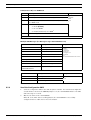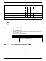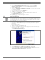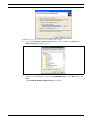
1
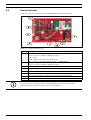
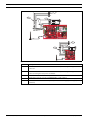
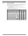
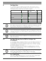
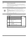
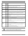
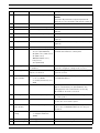
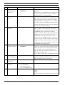
GPRS/GSM IP Communicator
Conettix ITS-DX4020-G
en
Installation and Operation Guide
GPRS/GSM IP Communicator
Table of Contents | en
3
Table of Contents
1
Introduction
5
1.1
Trademarks
5
1.2
Technical Specifications
5
1.3
Certifications and Approvals
6
1.4
Control Panel Compatibility
6
2
Overview
7
2.1
System Overview
7
2.2
Device Overview
8
2.3
Modes of Operation
2.4
Configuration Options
10
9
3
Installation
11
3.1
Installation Prerequisites
11
3.2
Insert the SIM Card
12
3.3
Mount the ITS-DX4020-G in the Control Panel Enclosure
13
3.4
Connect the ITS-DX4020-G to the Control Panel
14
3.5
Check Signal Strength
17
4
Configuration
18
4.1
Use Short Message Service (SMS) to Configure the ITS-DX4020-G
18
4.1.1
Enter CONFIG MODE
18
4.1.2
Compose the Configuration SMS
19
4.1.3
Send the Configuration SMS
20
4.1.4
Exit from CONFIG MODE
21
4.2
Use USB to Configure the ITS-DX4020-G
21
4.2.1
Install the USB Driver
22
4.2.2
Install a Communication Program
24
4.2.3
Log Into the USB Interface
25
4.2.4
USB Main Menu
27
4.2.5
USB Option Menu
27
4.3
Polling Configurations
31
4.3.1
High Security Application (bank, jewelry store, UL fire, and so on)
31
4.3.2
Medium Security Application
32
4.3.3
Backup or Low Security Application (residential or other once-a-day reporting location)
33
4.4
SIM Card Data Usage
34
5
Testing
35
5.1
GSM Trouble Indication
35
5.2
Firmware Version
35
6
Firmware Upgrade
36
6.1
Download the Latest Firmware
36
6.2
Install the Firmware
36
6.2.1
Install the Firmware using Hyper Terminal
36
Bosch Security Systems, Inc.
Installation and Operation Guide
F01U133268 | 03 | 2010.05
4
en | Table of Contents
GPRS/GSM IP Communicator
6.2.2
Install the Firmware using Tera Term
38
7
Troubleshooting
41
7.1
Diagnostic LED Descriptions
41
7.2
Troubleshooting Procedures
45
7.2.1
The ITS-DX4020-G does not power on (no LEDs are lit).
45
7.2.2
Initialization
45
7.2.3
Hardware
45
7.2.4
Firmware
45
7.2.5
Radio Registration
46
7.2.6
SIM Card
46
7.2.7
PIN Code
46
7.2.8
Control Panel Bus
47
7.2.9
No Authorization
47
7.2.10
Invalid Configuration SMS
47
7.2.11
Firmware Upgrade In Process
48
7.2.12
No Incoming IP Packets
48
7.2.13
Control Panel Bus Problem
48
7.2.14
Radio Initializing or No Signal Strength
49
7.2.15
GSM Network Registration
49
7.2.16
Unacceptable Signal Strength
49
7.2.17
Marginal RF Signal
50
7.2.18
Wireless Reception Issues
50
F01U133268 | 03 | 2010.05
Installation and Operation Guide
Bosch Security Systems, Inc.
GPRS/GSM IP Communicator
1
1.1
Introduction | en
5
Introduction
Trademarks
–
Microsoft, Windows 2000, XP, Vista, and Windows 7 are either registered trademarks or
trademarks of Microsoft Corporation in the United States and/or other countries.
–
1.2
Molex is a registered trademark of Molex Incorporated.
Technical Specifications
Electrical
Current (operating)
–
Standby: 65 mA
–
Alarm: 200 mA
Operating Voltage
12 VDC nominal
Maximum Wire Resistance for
1.6 ohms
Control Panel Connections
Maximum Wire Distance
–
0.64 mm (22 AWG): 30.5 m (100 ft)
–
1.02 mm (18 AWG): 61 m (200 ft)
Ripple/Noise
200 mVpp maximum
PSTN FSX Port
17 V minimum supplied
Radio
Terminals
GSM Quad band radio; 850 MHz and 1900 MHz
–
Europe: 900 MHz and 1800 MHz
–
North America: 850 MHz and 1900 MHz
All terminals are power-limited. Separate power-limited wiring from non-powerlimited wiring by 6.4 mm (0.25 in).
Environmental
Environment
Indoors
Relative Humidity
5% to 93% non-condensing
Temperature (operating)
-10°C to +55°C (+14°F to +131°F)
Mechanical
Dimensions (H x W x D)
Antenna
133 mm x 80 mm x 23 mm (5.2 in. x3.1 in. x 1 in.)
–
Magnetic base omni-directional antenna
–
2.5 m (8.2 ft) cable with SMA connector
SIM Card
3V/1.8V SIM (compliant with GSM 11.12 recommendation)
USB
Mini-B connector (cable not included)
Accessories
AE1 Standard Enclosure
Standard gray enclosure made of 1.0 mm cold-rolled steel. Includes a keyed lock.
The dimensions are 35.6 cm x 31.8 cm x 7.6 cm (14 in. x 12.5 in. x 3 in.).
AE2 Standard Enclosure
Standard red enclosure made of 1.0 mm cold-rolled steel. Includes a keyed lock.
Measures 35.6 cm x 31.8 cm x 7.6 cm (14 in. x 12.5 in. x 3 in.).
AE4 Large Enclosure
Large red enclosure made of 1.2 mm coldrolled steel. Includes a keyed lock.
Measures 52.7 cm x 38.1 cm x 10.8 cm (20.7 in. x 15 in. x 4.25 in.).
D2203 Enclosure
Grey steel enclosure measuring 37 cm x 34 cm x 8.9 cm
(14.6 in. x 13.4 in. x 3.5 in.). Includes a lock and accepts an optional tamper
switch.
Bosch Security Systems, Inc.
Installation and Operation Guide
F01U133268 | 03 | 2010.05
6
en | Introduction
GPRS/GSM IP Communicator
D8103 Enclosure
Grey steel enclosure measuring 41 cm x 41 cm x 9 cm (16 in. x 16 in. x 3.5 in.).
D8109 Fire Enclosure
Red steel enclosure measuring 40.6 cm x 40.6 cm x 8.9 cm
(16 in. x 16 in. x 3.5 in). UL Listed. Includes a lock and key set.
1.3
Certifications and Approvals
The ITS-DX4020-G is designed to comply with the following certifications and approvals:
Agency
Certification
Australia
A-Tick Approved
CE
EN60950 Safety
EN50130-4 Electromagnetic Compatibility
–
EN55022 Radiated/Conducted Emissions
FCC
FCC, Part 15 Radiated/Conducted Emissions
NIST
FIPS 197 Certificate No.
PTCRB
Approved
CSFM
Approved
UL
1.4
–
–
–
UL 365, Police Station Burglar Alarm Units and Systems
–
UL 864, UL Commercial Fire Alarm Signaling
–
UL 985, Household Fire Warning System Units
–
UL 1023 Household Burglar-alarm System Units
–
UL 1610, Central Station Burglary
Control Panel Compatibility
–
DS7200V2 Series (firmware version 2.10 or later)
–
DS7400XiV4 (firmware version 4.10 or later)
–
FPD-7024 Fire Alarm Control Panel
–
Easy Series (firmware version 3.0 or later)
–
GV2 Series (firmware version 7.07 or 7.081
–
GV3 Series
Refer to your control panel's documentation for programming instructions. When
programming the ITS-DX4020-G, follow your control panel’s DX4020 network programming
instructions.
F01U133268 | 03 | 2010.05
Installation and Operation Guide
Bosch Security Systems, Inc.
GPRS/GSM IP Communicator
2
Overview | en
7
Overview
The ITS-DX4020-G enables two-way IP or dialed communication over a commercial GPRS /
GSM network. Typical applications are event reporting to a central monitoring station and
remote access to Bosch intrusion control panels. For a list of compatible control panels, refer
to Section 1.4 Control Panel Compatibility, page 6.
For installations using a PSTN receiver, the ITS-DX4020-G uses GSM to dial the receiver and
communicate using Contact ID.
2.1
System Overview
44
33
22
5
5
11
66
7
7
88
11
11
99
12
12
13
13
14
14
10
10
15
15
Figure 2.1 System Overview
Callout
Description
1
ITS-DX4020-G GPRS/GSM Communicator
2
Compatible Control Panel
(refer to Section 1.4 Control Panel Compatibility, page 6)
3
Control Panel Dialer Connection (optional)
4
Control Panel Bus and Power Connection
5
USB Type A (host)-to-USB Mini B (device) Cable (not included)
6
Local PC or SMS-capable Cell Phone for Configuration
7
Antenna Cable
8
Magnetic Base Antenna
9
Base Station on Wireless Carrier’s Network
10
Internet, WAN, Ethernet, or PSTN network
11
Remote PC’s Network Connection
12
Remote PC Running Remote Programming Software (RPS)
13
Ethernet Connection
14
PSTN Connection
15
Conettix D6600 with Serial Network Adapter or Conettix D6100i Receiver
Bosch Security Systems, Inc.
Installation and Operation Guide
F01U133268 | 03 | 2010.05
8
2.2
en | Overview
GPRS/GSM IP Communicator
Device Overview
Figure 2.2 shows an overview of the ITS-DX4020-G printed circuit board (PCB).
Figure 2.2 ITS-DX4020-G PCB Overview
Callout
Description
1
PNL/PSTN terminals (for GSM/PSTN Mode)
Refer to Section 2.3 Modes of Operation, page 9.
PNL = Panel
PSTN = Public Switched Telephone Network
2
Molex connector and bus terminals (for IP over GPRS Mode)
Refer to Section 2.3 Modes of Operation, page 9.
3
Mini-B USB Port
4
ANTENNA Connector
5
CONFIG MODE (J200) Jumper Pins
6
LED DIS (J201) Jumper Pins (LED Disable Jumper Pins)
7
Diagnostic LEDs. Refer to Table 7.2, Page 44, for more information.
8
SIM card in card holder
NOTICE!
To conserve power, disable the diagnostic LEDs by placing a jumper plug across the
LED DIS jumper pins. Refer to Figure 2.2 for more information.
F01U133268 | 03 | 2010.05
Installation and Operation Guide
Bosch Security Systems, Inc.
GPRS/GSM IP Communicator
2.3
Overview | en
9
Modes of Operation
NOTICE!
The IP over GPRS Mode requires a data plan enabled SIM from a cellular provider.
The ITS-DX4020-G supports two modes of operation. Refer to Table 2.1 for a description of
each mode.
IP over GPRS (General Packet Radio Services) Mode
Overview:
This mode provides a wireless IP connection over the GPRS network.
The control panel supervises the communication path through the ITS-DX4020-G either by
control panel heartbeats, or by periodic test reports.
Wiring connections:
Connect the bus terminals on the control panel and the ITS-DX4020-G.
Refer to Figure 3.3, Page 14.
Supported control panels:
Refer to Section 1.4 Control Panel Compatibility, page 6.
Table 2.1 IP over GPRS Mode of Operation
PSTN (Contact ID) over GSM
Overview:
This mode:
–
Provides a GSM dial-out option for installation sites where GPRS service is not
available or a Conettix receiver is not available
–
Supports only the Contact ID reporting format
NOTICE: For control panels that detect a dial tone before dialing, disable dial tone
detection. The ITS-DX4020-G supplies phone voltage of 22 - 25 VDC and US dial tone
frequencies (350 Hz+ 440 Hz).
Wiring connections:
Connect the R (Ring) and T (Tip) phone terminals from the control panel to the PNL/PSTN
terminals on the ITS-DX4020-G.
Refer to Figure 3.4, Page 15
Supported control panels:
All. Refer to Section 1.4 Control Panel Compatibility, page 6.
Table 2.2 PSTN (Contact ID) over GSM Mode
Dual Wireless Mode (Default Mode)
Overview:
This mode combines the IP over GPRS and PSTN (Contact ID) over GSM modes.
Wiring connections:
–
Connect the bus terminals on the control panel and the ITS-DX4020-G.
–
Connect the R (Ring) and T (Tip) phone terminals from the control panel to the
PNL/PSTN terminals on the ITS-DX4020-G.
Refer to Figure 3.5, Page 16.
Supported control panels:
Easy Series (firmware version 3.0 or later).
Bosch Security Systems, Inc.
Installation and Operation Guide
F01U133268 | 03 | 2010.05
10
2.4
en | Overview
GPRS/GSM IP Communicator
Configuration Options
You can configure the ITS-DX4020-G using one of two methods:
–
Short Message Service (SMS). Refer to Section 4.1 Use Short Message Service (SMS) to
Configure the ITS-DX4020-G, page 18.
–
USB user interface. Refer to Section 4.2 Use USB to Configure the ITS-DX4020-G, page 21.
You can configure in one of three different modes, depending on the control panel. For a list
of modes allowed by the different control panels, refer to Table 4.1, Page 18.
NOTICE!
The configuration options provide temporary connections to the ITS-DX4020-G for
configuration purposes only. They are not intended for long-term, or permanent, connection.
F01U133268 | 03 | 2010.05
Installation and Operation Guide
Bosch Security Systems, Inc.
GPRS/GSM IP Communicator
Installation | en
3
Installation
3.1
Installation Prerequisites
11
Before you install the ITS-DX4020-G, ensure that the following prerequisites are met:
–
Before installing the ITS-DX4020-G in an existing system, inform the operator and local
authority.
–
Before installing the ITS-DX4020-G, disconnect all system power (AC and standby
battery).
–
If you are mounting the ITS-DX4020-G in a separate enclosure, ensure that all external
wiring does not exceed 1.6 ohms: 30.5 m (100 ft) of 0.64 mm (22 AWG) or 61 m (200 ft)
of 1.02 mm (18 AWG) wire. Refer to Section 1.2 Technical Specifications, page 5, for
optional enclosures (if required).
–
Separate power-limited wiring from non-power-limited wiring by 6.4 mm (0.25 in).
–
Contact the central monitoring station for destination IP address and port number
settings. Provide the central monitoring station with the poll rate setting.
NOTICE!
Depending on the SIM card used, first-time registration of the SIM card might take up to 3
minutes to complete. During this time, the signal levels displayed by the signal strength LEDS
might fluctuate.
Bosch Security Systems, Inc.
Installation and Operation Guide
F01U133268 | 03 | 2010.05
12
3.2
en | Installation
GPRS/GSM IP Communicator
Insert the SIM Card
Figure 3.1 SIM Card and Card holder Overview
Callout
Description
1
SIM card orientation
2
SIM card holder door unlock instruction
3
SIM card holder door open instruction
4
SIM card insert instruction
5
SIM card holder door close and lock instruction
1.
Hold the ITS-DX4020-G communicator as shown in Figure 3.1.
2.
Slide the SIM card holder door upward to unlock it.
3.
Lift the SIM card holder door.
NOTICE!
The SIM card holder door does not open very far. Do not force the door open beyond its
normal range of motion.
4.
Insert the SIM card into the guides on the card holder door.
The notched edge is away from the hinge, and the contacts are positioned as shown in
Figure 3.1.
5.
F01U133268 | 03 | 2010.05
Close the card holder door, and then slide the door away from the hinge to lock it.
Installation and Operation Guide
Bosch Security Systems, Inc.
GPRS/GSM IP Communicator
3.3
Installation | en
13
Mount the ITS-DX4020-G in the Control Panel Enclosure
Refer to Figure 3.2, Page 13.
1.
Mount the ITS-DX4020-G into the control panel's enclosure using the supplied mounting
screws.
Use any of the standard three-hole mounting patterns on the control panel’s enclosure. If
necessary, remove the three knockouts.If necessary, use the D137 Mounting Bracket (not
supplied) to mount the ITS-DX4020-G on the control panel enclosure.
2.
Place the magnetic antenna in the vertical position on the top of the control panel
enclosure or other metal surface.
NOTICE!
The antenna must be placed on a magnetic metal surface for proper operation.
For best performance, ensure that the surface area extends 10 cm (4 in.) or more in all
directions around the antenna.
3.
Connect the antenna cable to the ITS-DX4020-G.
Figure 3.2 Sample Mounting Location in Control Panel Enclosure
Callout
Description
1
Sample mounting location and ITS-DX4020-G mounted at that location with
supplied mounting screws
2
Magnetic antenna (mount on top of the enclosure or other metallic surface);
route the antenna cable through the enclosure knockout
3
Bosch Security Systems, Inc.
ANTENNA connector on ITS-DX4020-G
Installation and Operation Guide
F01U133268 | 03 | 2010.05
14
3.4
en | Installation
GPRS/GSM IP Communicator
Connect the ITS-DX4020-G to the Control Panel
Depending on the selected mode of operation, refer to Figure 3.3 below, or Figure 3.4,
Page 15 for wiring connections.
NOTICE!
The bus terminals are shown in only one order. Terminal order is specific to control panel
type. Refer to the control panel documentation for more information.
For more information on the modes of operation, refer to Section 2.3 Modes of Operation,
page 9.
B
G
Y
R
1a
1b
2
B
G
Y
R
2
Figure 3.3 Connections for IP over GPRS Mode
Callout
Description
1a
Bus connection from ITS-DX4020-G to the control panel using the supplied
Molex cable
1b
Bus connection from the ITS-DX4020-G to the control panel using the bus
power terminals
2
F01U133268 | 03 | 2010.05
Bus power terminals on the control panel
Installation and Operation Guide
Bosch Security Systems, Inc.
GPRS/GSM IP Communicator
Installation | en
4
3
1a
B
G
Y
R
15
2
R
RH
TH
T
3
4
B
G
Y
R
2
R
RH
TH
T
1b
Figure 3.4 Connections for PSTN (Contact ID) over GSM Mode
Callout
Description
1a
Power connection from ITS-DX4020-G to the control panel (12 VDC only) using
the supplied Molex cable
1b
Power connection from ITS-DX4020-G to the control panel (12 VDC only) using
the bus terminals
2
Bus terminals on the control panel
3
PNL/PSTN connection from ITS-DX4020-G to the control panel
4
Phone terminals on the control panel (connect to the Ring [R] and Tip [T]
terminals)
Bosch Security Systems, Inc.
Installation and Operation Guide
F01U133268 | 03 | 2010.05
16
en | Installation
GPRS/GSM IP Communicator
B
G
Y
R
1a
3
4
2
R
RH
TH
T
B
G
Y
R
3
2
4
R
RH
TH
T
1b
Figure 3.5 Connections for Dual Wireless Mode
Callout
Description
1a
Bus connection from ITS-DX4020-G to the control panel using the supplied Molex
connector
1b
Bus connection from ITS-DX4020-G to the control panel using the supplied Molex
connector using the bus power terminals
2
Power terminals on the control panel
3
PNL/PSTN connection from ITS-DX4020-G to control panel
4
Phone terminals on the control panel (connect to the Ring [R] and Tip [T]
terminals)
F01U133268 | 03 | 2010.05
Installation and Operation Guide
Bosch Security Systems, Inc.
GPRS/GSM IP Communicator
3.5
Installation | en
17
Check Signal Strength
Apply power to the ITS-DX4020-G and wait 30 sec. Depending on the SIM card used, first-time
registration might take up to 3 minutes to complete. If any LEDs have a double flash, refer to
Table 7.2, Page 44 and proceed when the double-flash problem is resolved.
Check the signal strength LEDs (SS1, SS2, and SS3):
–
If the signal strength is good or higher (refer to Table 3.1, Page 17), proceed to
Section 4 Configuration, page 18.
–
If the signal strength is unacceptable or lower (refer to Table 3.1, Page 17), check the
installation site for possible causes of signal interference.
Refer to Table 3.1 for signal strength levels.
LED
Signal Strength
SS1
SS2
SS3
Unacceptable: no reading available
Off
Off
Off
Flash
Off
Off
Unacceptable: < -89 dBm
On
Off
Off
Marginal: -89 dBm to -83 dBm
On
Flash
Off
Good: -83 dBm to -77 dBm
On
On
Off
Very good: -77 dBm to -69 dBm
On
On
Flash
Excellent: > -69 dBm
On
On
On
(modem is resetting or registering)
Attempting to register on the GSM
network.
Table 3.1 Signal Strength Levels
Bosch Security Systems, Inc.
Installation and Operation Guide
F01U133268 | 03 | 2010.05
18
en | Configuration
4
GPRS/GSM IP Communicator
Configuration
The ITS-DX4020-G supports configuration by either SMS or USB connection. You can
configure up to two different modes, depending on the control panel. For a list of modes
allowed by the different control panels, refer to Table 4.1, Page 22.
Control Panel
GPRS (IP)
PSTN (Contact ID)
DUAL
over GSM
Easy Series
DS7240V2 Series
DS7400xiV4
FPD-7024
GV2 Series
GV3 Series
Table 4.1
Modes Allowed by Control Panel
NOTICE!
When using the PSTN (Contact ID) over GSM mode on a GV3 Series control panel, ensure that
the “C” character is dialed before the central station’s phone number. The "C" character
disables dial tone detection after the first DTMF digit is dialed.
NOTICE!
Bosch recommends that when using GSM mode, always enter a 10-digit phone number in the
control panel. This is because the SIM card might have originated in a different area code from
the installation location.
NOTICE!
When using the PSTN (Contact ID) over GSM mode, the control panel must be set up for
DTMF (tone) dialing only.
4.1
Use Short Message Service (SMS) to Configure the
ITS-DX4020-G
The ITS-DX4020-G supports configuration by SMS. You can send the SMS via mobile phone to
the ITS-DX4020-G. The SMS string follows a specific format. If the configuration message
exceeds 160 characters, you must send multiple messages. Refer to Section 4.1.2 Compose
the Configuration SMS, page 19 for details.
When the ITS-DX4020-G receives the final valid part of an SMS message, it accepts the
configuration. The ITS-DX4020-G waits as long as the CONFIG MODE jumpers are shorted
together with the supplied jumper plug.
NOTICE!
To allow the receipt of SMS data, the CONFIG MODE jumper pins must be shorted together
with the supplied jumper plug. Refer to Table 4.6, Page 21, for LED activity.
If the CONFIG MODE jumper pins are not shorted together, incoming SMS data is discarded.
4.1.1
Enter CONFIG MODE
Ensure that the CONFIG MODE jumper pins are shorted together with the supplied jumper
plug. The STATUS, CELL IP, and AUDIO ACT LEDs start a scrolling pattern.
F01U133268 | 03 | 2010.05
Installation and Operation Guide
Bosch Security Systems, Inc.
GPRS/GSM IP Communicator
4.1.2
Configuration | en
19
Compose the Configuration SMS
Use the appropriate SMS template for the selected mode of operation, and compose the
configuration SMS message on your mobile phone. SMS can contain only 160 characters.
Refer to Section Multiple SMS Messages (for Messages Longer than 160 Characters), page 20 for
instructions for sending a multiple SMS configuration.
The templates below contain only the essential configuration IDs. For additional configuration
IDs, refer to Table 4.9, Page 30.
NOTICE!
Separate each ID or value pair with a line feed (<LF>), a carriage return (<CR> or
<
ENTER>), or a semi-colon <;>. Because of phone and carrier differences, Bosch
recommends using semi-colons to create and send SMS messages (for example,
%1;1=4020G;10=Airnet1;14=88;17=2;!). To allow spanning of configuration across multiple
messages, each SMS starts with the sequence number followed by the command line
separator.
Any of these characters is acceptable to separate command lines. Refer to your cellular
phone’s documentation for available characters.
Refer to Table 4.1, Page 18 for information about the modes allowed for your control panel.
IP over GPRS Mode
ID
Description
Sample SMS
%1
SMS sequence number 11
1=
Current password (4 to 15 characters); default = 4020G
10=
GPRS access point name (APN); 1 to 63 characters
14=
–
13 or 14 (DS7400XiV4)
%1
1=4020G
10=basic.m2m
14=88
17=2
!
–
88 (GV2 Series, GV3 Series)
17=
!
1
–
92 (GV3 Series)
–
134 (DS7200V2 Series, Easy Series)
–
250 (FPD-7024)
Communication path:
–
1 = Both (default)
–
2 = IP over GPRS
–
3 = PSTN (Contact ID) over GSM
End of configuration
The % symbol starts the SMS configuration message content. Any data before the % symbol is discarded.
The % symbol is followed directly by the sequence number of the message (1 to 3).
Table 4.2 IP over GPRS Mode and Dual Wireless Mode SMS Configuration
Bosch Security Systems, Inc.
Installation and Operation Guide
F01U133268 | 03 | 2010.05
20
en | Configuration
GPRS/GSM IP Communicator
PSTN (Contact ID) over GSM Mode
ID
Description
%1
SMS sequence number 1
1=
Current password (4 to 15 characters); default = 4020G
14=
Sample SMS
Control panel bus address 0 to set it to PTSN (Contact ID)
over GSM mode
17=
%1
1=4020G
14=0
17=3
!
Communication path:
!
–
1 = Both (default)
–
2 = IP over GPRS
–
3 = PSTN (Contact ID) over GSM1
End of configuration
1
Select 3 (PSTN (Contact ID) over GSM) for PSTN over GSM Mode
Table 4.3
PSTN (Contact ID) over GSM Mode SMS Configuration
Multiple SMS Messages (for Messages Longer than 160 Characters)
ID
Description
%1<LF>
SMS sequence number 1
1=4020G<LF>
Current password
2=secret123<LF>
New password (case sensitive)
3=123456,4343<LF>
PUK and new PIN to set in SIM
10=basic.m2m<LF>
(Access Point Name) APN
[email protected]<LF>
GPRS username
12=password<LF>
GPRS password
15=1<LF>
Enable AES encryption
Sample SMS
%1
1=4020G
2=secret123
3=123456,4343
10=basic.m2m
[email protected]
12=password
15=1
16=01020304050607080910111213141516
16=01020304050607080910 Sample AES key
111213141516<LF>
Table 4.4
ID
Description
%2<LF>
SMS sequence number
14=134<LF>
Option bus address
!
End of configuration
Table 4.5
4.1.3
Double SMS Example, Part 1
Sample SMS
%2
14=134
!
Double SMS Example, Part 2
Send the Configuration SMS
1.
Send the configuration SMS to the SIM card phone number. The transmission might take
several minutes. Because the CONFIG jumper is on, the ITS-DX4020-G waits for an SMS
until a message is received.
2.
Observe the LEDs on the ITS-DX4020-G.
When all of the LEDs start a scrolling pattern, the ITS-DX4020-G is successfully
configured. Refer to Table 4.6 for more information.
F01U133268 | 03 | 2010.05
Installation and Operation Guide
Bosch Security Systems, Inc.
GPRS/GSM IP Communicator
Configuration | en
21
LED State
Condition
STATUS CELL
AUDIO SS1
SS2
SS3
BUS
IP
1
No control panel authorization received.
2
Installer is authorized for Configuration mode,
or authorization is not required.
3
Received invalid SMS.
4
Received valid SMS authorizing configuration.
→
→
→
→
→
→
→
→
→
→
→
→
GSM Signal Strength
Off
GSM Signal Strength
On
Flash
Flash
Flash
Flash
→
→
→
→
Key: → = Scrolling LEDs, from left to right.
Table 4.6
Configuration Mode (J200 Jumper Installed) LED States
NOTICE!
If the LEDs indicate an invalid SMS, remove the configuration jumper and then repeat the
steps in Section 4.1.1 Enter CONFIG MODE, page 18.
If the LEDs continue to indicate an invalid SMS, the configuration SMS might be incorrect.
Ensure that your configuration SMS contains the correct information, or use the USB
connection to configure the ITS-DX4020-G.
4.1.4
Exit from CONFIG MODE
1.
Remove the jumper plug from the CONFIG MODE jumper pins.
The ITS-DX4020-G restarts.
2.
Check the status of the CELL IP LED to see if the ITS-DX4020-G can communicate with
the central station receiver.
Refer to Table 4.7 for more information.
CELL IP LED State
Status
Off
The ITS-DX4020-G is not connected to the GPRS network.
Flash
The ITS-DX4020-G is connected to the GPRS network, but it is not
connected to the central station receiver.
On
The ITS-DX4020-G is connected to the central station receiver
through the GPRS network.
Table 4.7 CELL IP LED Status
4.2
Use USB to Configure the ITS-DX4020-G
You can use a USB connection from a laptop or desktop PC to the ITS-DX4020-G to configure
the ITS-DX4020-G on-site.
Before you can access the USB user interface, you must install the ITS-DX4020-G.inf file on
the target PC or laptop. The ITS-DX4020-G.inf file is available on the supplied CD-ROM. You
need to install this file only once on the target PC or laptop.
If the ITS-DX4040-G CD-ROM is not available:
1.
From your Internet browser, go to http://www.boschsecurity.com to open the Bosch
Web site.
2.
Select the web site for your region and country.
3.
In the Online Catalogs section on the left, click the Intrusion Alarm Systems link.
Bosch Security Systems, Inc.
Installation and Operation Guide
F01U133268 | 03 | 2010.05
22
en | Configuration
GPRS/GSM IP Communicator
4.
Under the Intrusion Alarm Systems Products heading, scroll to the Conettix Information Transport Solutions section. Click the Show product section link.
5.
Click the Conettix IP link.
6.
Scroll to the ITS-DX4020-G GPRS/GSM IP Communicator section. Click the section title
to open the product page.
7.
Under the product image, click the Software tab.
8.
Click OK to accept the license agreement.
9.
To the right of ITS-DX4020-G inf, click on the language link (for example, en).
The File Download dialog box opens.
10. Click Save to save the file to the target PC or laptop.
4.2.1
Install the USB Driver
NOTICE!
If the target PC or laptop has only one USB port, you need to install the USB driver only once.
If the target PC or laptop has multiple USB ports, you must install the USB driver each time
the ITS-DX4020-G is connected to a new USB port.
1.
Ensure that the CONFIG MODE jumper pins are shorted together with the supplied
jumper plug.
Refer to Figure 2.2, Page 8.
2.
3.
Supply power to the ITS-DX4020-G (12 VDC).
Connect the ITS-DX4020-G to the target PC or laptop, using a USB-to-mini-USB (5-pin
mini-B connector) cable (not supplied).
The Found New Hardware Wizard opens.
Figure 4.1 Found New Hardware Wizard Main Page
4.
5.
Select Install from a list or specific location (Advanced), and click Next.
On the resulting Please choose your search and installation options page, select the
Search for the best driver in these locations option button.
F01U133268 | 03 | 2010.05
Installation and Operation Guide
Bosch Security Systems, Inc.
GPRS/GSM IP Communicator
Configuration | en
23
Figure 4.2 Please Choose Your Search and Installation Options Page
6.
Select the Include this location in the search checkbox, and then click Browse. The
Browse for Folder dialog box opens.
Figure 4.3 Browse for Folder Dialog Box
7.
Navigate to and highlight the downloaded ITS-DX4020-G.inf file. Click OK and then click
Next.
The Found New Hardware Wizard Finish page appears.
Bosch Security Systems, Inc.
Installation and Operation Guide
F01U133268 | 03 | 2010.05
24
en | Configuration
GPRS/GSM IP Communicator
Figure 4.4 Found New Hardware Wizard Finish Page
8.
4.2.2
Click Finish to complete the installation of the ITS-DX4020-G USB driver.
Install a Communication Program
To use a USB connection from a laptop or desktop PC to the ITS-DX4020-G to configure the
ITS-DX4020-G, you must use a Microsoft communication program.
–
Windows XP and Earlier: The Microsoft Windows XP and 2000 installation automatically
installs HyperTerminal, a Microsoft communication program, when Windows installs. If
HyperTerminal is not installed, install it from the Windows XP or Windows 2000
installation disc, or install Tera Term from the ITS-DX4020-.
–
Windows Vista and Windows 7: Windows Vista and Windows 7 installations do not
install a communication program when the operating system installs. Install Tera Term
from the ITS-DX4020-G CD.
When you perform the installation, follow the prompts in the installation wizard, but on the
Select Components page of the wizard, select Compact installation from the drop-down list.
Refer to Figure 4.5, Page 24.
Figure 4.5 Setup - Tera Term Wizard’s Select Components Page
F01U133268 | 03 | 2010.05
Installation and Operation Guide
Bosch Security Systems, Inc.
GPRS/GSM IP Communicator
4.2.3
Configuration | en
25
Log Into the USB Interface
NOTICE!
To allow for USB configuration, the CONFIG MODE jumper pins must be shorted together with
the supplied jumper plug. Refer to Table 4.6, Page 21, for LED activity.
If the CONFIG MODE jumper pins are not shorted together, you can only view configuration
data.
1.
Ensure that the USB-to-mini-USB cable is connected to the ITS-DX4020-G and the target
PC or laptop.
2.
Short the CONFIG MODE jumper pins with the supplied jumper plug.
3.
From Windows, start a terminal session by doing one of the following:
–
If you are using Windows XP or earlier, launch Hyper Terminal by selecting Start>(All)
Programs>Accessories>Communications>Hyper Terminal.
–
In you are using Windows Vista or Windows 7, launch Tera Term by selecting Start>(All)
Programs>Tera Term>Tera Term.
4.
Set up a connection on the new virtual serial COM port (for example, Port: COM4:
ITS-DX4020-G [COM4]) using the following settings:
–
Baud rate: 9600
–
Data bits: 8
–
Parity: None
–
Stop bits: 1
–
Flow control: None
To determine which COM port is used by the ITS-DX4020-G:
a.
From your desktop, click Start.
b.
Right-click My Computer, and select Properties.
c.
Select the Hardware tab, and click the Device Manager button.
d.
In the Device Manager list, scroll to Ports (COM & LPT).
e.
Open the Ports (COM & LPT) node.
If the ITS-DX4020-G is connected to the computer, it appears in this list with its
COM port assignment next to it.
If the ITS-DX4020-G is not connected to the computer, or the USB driver is not
installed, the ITS-DX4020-G does not appear in this list.
5.
After the connection is established, press [Enter].
The ITS-DX4020-G USB login window opens.
Bosch Security Systems, Inc.
Installation and Operation Guide
F01U133268 | 03 | 2010.05
26
en | Configuration
GPRS/GSM IP Communicator
Figure 4.6 ITS-DX4020-G USB Login Window
NOTICE!
The ITS-DX4020-G USB login window shows the firmware version. The procedures in this
installation and operation guide require software version 1.3.15 or later. Refer to
Section 6 Firmware Upgrade, page 36 for firmware upgrade instructions.
6.
Enter the password to log on. The default password is 4020G (all uppercase).
The user interface allows three attempts to enter the password correctly. After three
failed attempts, you must reset the ITS-DX4020-G by removing the jumper plug from the
CONFIG MODE jumpers, and then repeat Steps 3 through 6.
7.
F01U133268 | 03 | 2010.05
Press [Enter] to continue. The USB main menu opens. Refer to Figure 4.7, Page 27.
Installation and Operation Guide
Bosch Security Systems, Inc.
GPRS/GSM IP Communicator
4.2.4
Configuration | en
27
USB Main Menu
Figure 4.7 USB Main Menu
Callout
Description
1
Current access level
2
Current settings for basic parameters
3
Asterisk (*) preceding the Basic or Advanced configuration items indicates a
change made to a configuration item during current session.
4
Current settings for advanced parameters
5
Current device status
6
USB option menu. Refer to Section 4.2.5 USB Option Menu, page 27.
The USB main menu appears:
–
–
after a user enters a password successfully
every time the user presses [Enter] without first selecting an option from the main
screen, or
–
upon returning from a sub-menu.
The main menu shows all current configuration settings first. An asterisk in front of a Basic or
Advanced configuration item indicates a setting change during the current session.
The content of the main menu scrolls continuously. When a user performs a new action, any
resulting response from the user interface appears at the end of the menu.
4.2.5
USB Option Menu
For a description of the USB option menu items, refer to Table 4.8, Page 28.
To see the USB option menu, refer to Figure 4.7, Page 27.
At a configuration screen, items are presented one at a time with the current value inside [ ]
brackets. If you press [Enter] without entering a new value, the current value is unchanged.
To go to a specific menu option, enter the appropriate menu item number and press [Enter].
Bosch Security Systems, Inc.
Installation and Operation Guide
F01U133268 | 03 | 2010.05
28
en | Configuration
Option
GPRS/GSM IP Communicator
Press
Description
to
Select
1 Change
1
To change the login password, enter the old password first, and then enter the new
password
password twice. The second entry confirms the new password.
Passwords must be 4-15 characters long, and are case-sensitive.
0-9, A-Z, a-z, and special characters are allowed.
2 Change log
2
Change the debugging level shown on the View Log screen.
3 View log
3
View the debugging log for diagnostic purposes. Press any key to exit.
4 Exit without
4
Return to the USB interface login screen. Press [Y] (for Yes) to exit without saving. All
level
Save
configuration changes that were made are lost and are replaced with the previous
values.
5 Restore
5
Select to restore all factory default values.
Factory defaults
When prompted, remove the plug from the CONFIG jumper pins to restart the
ITS-DX4020-G. Warning: All fields are cleared and the factory default values are
restored.
6 Save and
6
Select to save all changed values (changed values are preceded by an asterisk [*]).
Reboot
Press [Y] (for Yes).
When prompted, remove the plug from the CONFIG jumper pins to restart the
ITS-DX4020-G.
7 Upgrade
7
Select this option to upgrade the firmware in the ITS-DX4020-G.
Firmware
8 Change Basic
Refer to Section 6 Firmware Upgrade, page 36.
8
To change a basic parameter:
parameters
1. Press the [Enter] key repeatedly until the cursor is on the desired parameter.
2. Enter the desired value. If you do not enter a new value at the prompt, the previous
value is retained.
After all Basic parameters are reviewed, the USB main menu reappears, indicating
changed values with asterisks (*).
Refer to Table 4.9, Page 30 for basic parameters.
9 Change
9
To change an advanced parameter:
Advanced
1. Press the [Enter] key repeatedly until the cursor is on the desired parameter.
parameters
2. Enter the desired value. If you do not enter a new value at the prompt, the previous
value is retained.
After all Advanced parameters are reviewed, the USB main menu re-appears,
indicating changed values with an asterisk (*).
Refer to Table 4.9, Page 30 for advanced parameters.
Table 4.8
USB Option Menu Items
NOTICE!
Table 4.9 shows all parameters available through SMS or USB configuration.
Shaded rows are required parameters. Values in bold are default settings.
F01U133268 | 03 | 2010.05
Installation and Operation Guide
Bosch Security Systems, Inc.
GPRS/GSM IP Communicator
Configuration | en
ID
Parameter
Values
Description
1
Current Password
4 to 15 characters (4020G)
Mandatory and case sensitive.
29
NOTICE!
Remember all passwords. Forgotten passwords
cannot be recovered, and the unit must be returned.
2
New Password
4 to 15 characters
New password, as desired. Case sensitive.
3
SIM PUK,PIN
Maximum 10 numeric digits each Sets a new PIN into the SIM and the ITS-DX4020-G.
4
SIM PIN
4 numeric digits
Sets the PIN in the ITS-DX4020-G to match your SIM
card PIN.
10
GPRS APN
1 to 63 characters (Airnet1)
Access point name.
11
GPRS username
1 to 63 characters
User name for wireless service provider (not always
required).
12
GPRS password
1 to 63 characters
Password for wireless service provider (not always
required).
13
Src port
1 to 65535 characters (7700)
Sets the source port for the ITS-DX4020-G.
14
Bus Address
–
0 (PSTN [Contact ID])
Sets the control panel bus address for
–
13 or 14 (DS7400XiV4)
communication with the control panel.
–
88 (GV2 Series, GV3 Series)
–
92 (GV3 Series)
–
134 (DS7200V2 Series,
–
250 (FPD-7024)
Easy Series)
15
16
17
AES Encryption
0 = Disabled
Security encryption on or off. The setting must
1 = Enabled
match the encryption settings in the receiver.
32 characters max.
The AES Encryption Key must match the encryption
0-9, A-F, a-f allowed
key in the receiver.
Communication
–
1 = Both
Select which communication path the
paths available
–
2 = IP over GPRS
ITS-DX4020-G will use.
–
3 = PSTN (Contact ID) over
AES Encryption Key
GSM
18
Destination Port
1 to 65535 characters (7700)
Sets the port of the receiver for panels that do not
support a destination port (DS7400XiV4). This
setting appears in the USB interface menu only
when address 13 or 14 is selected.
50
DTMF digit timeout
100 to 3000 ms (500 ms)
Acceptable time between dialed DTMF digits from
the control panel.
51
GPRS ACK timeout
6 to 600 sec (70 sec)
The GPRS session restarts if no response occurs by
the time the entered time expires.
52
GPRS Transmit
6 to 120 sec (15 sec)
buffer lifetime
Length of time the control panel messages remain
in the in the ITS-DX4020-G buffer before they are
discarded.
53
GSM CODEC
–
0 = Full Rate (FR)
setting
–
1 = Adaptive Multi-rate
54
GSM transmit gain
0 to 10 (5)
Gain on transmitted GSM signals.
55
GSM receive gain
0 to 10 (5)
Gain on received GSM signals.
Set to Full Rate when GSM is used.
(AMR)
Bosch Security Systems, Inc.
Installation and Operation Guide
F01U133268 | 03 | 2010.05
30
ID
56
en | Configuration
GPRS/GSM IP Communicator
Parameter
Values
Description
Enable incoming
–
0 = Disabled
Enable or disable the ability to receive incoming
GSM calls where
–
1 = Enabled
GSM calls.
supported
This parameter is only available when using the Easy
Series control panel. Refer to Section 2.2 Device
Overview, page 8, for more information.
57
GPRS session
1 to 255 hrs (4 hrs)
timeout
If no IP over GPRS communication occurs within the
GPRS session timeout period, the ITS-DX4020-G
sends a message to keep the current session alive,
ensuring that the network path is active. To avoid
connectivity delays, set the GPRS session timeout
to fewer hours than your carrier's session expiration
period to avoid connectivity delays.
58
Trouble reporting
0 to 65535 sec (120 sec)
delay time
When low signal strength, SIM card missing, or
unable to register on the network is detected for
longer than the time entered in this parameter, the
ITS-DX4020-G stops responding on the bus to
indicate a Trouble condition to the control panel. No
information is sent to the control panel. The next
attempt by the control panel to poll, or send a
message to the ITS-DX4020-G, fails. The control
panel then creates a trouble condition. When signal
strength is detected, it must remain restored for the
amount of time entered in this parameter before the
ITS-DX4020-G sends signals again.
59
Enable low signal
–
0 = Disabled
When enabled, the ITS-DX4020-G sends a trouble
strength reporting
–
1 = Enabled
signal to the control panel if the signal strength falls
to an unacceptable level. Restoring signal strength
to an acceptable level resets this condition. For
proper operation, the signal strength must be at a
minimally an acceptable level.
Refer to Table 4.9, Page 30 for UL 864 requirements.
61
Dynamic DNS
7 to 15 characters (“none”)
Server IP Address
Enter an IP address using the standard IP address
format (for example, 10.10.10.1). Select “none” to
disable the dynamic DNS server update.
62
Dynamic DNS
1 to 65535 (7702)
Enter a DNS server port number, if applicable.
Dynamic DNS ID
–
1 = SIM ICCID
Select a DNS ID method.
Selection
–
2 = ID is SIM IMSI
–
3 = ID is modem IMEI
–
4 = ID is manually entered
Server Port
63
64
Dynamic DNS ID
2 to 20 characters
Must conform to RFC952 and RFC1123 name
format.
NOTICE!
This field is required only if parameter 63 is set to 4.
Table 4.9
SMS and USB Configuration Parameters
F01U133268 | 03 | 2010.05
Installation and Operation Guide
Bosch Security Systems, Inc.
GPRS/GSM IP Communicator
4.3
Configuration | en
31
Polling Configurations
Plan carefully when selecting the control panel poll time, ACK wait times, control panel
retries, ITS-DX4020-G GPRS ACK timeouts, and D6x00 Receiver poll and ACK wait times.
Having the wrong or improper settings could cause trouble conditions when the network
carrier performs maintenance, and increased data volumes that could effect your monthly
cost. Your settings for these parameters determine how the system works, but depend on the
security level needed.
4.3.1
High Security Application (bank, jewelry store, UL fire, and so on)
Polling times are typically less than 20 min. Path integrity is critical, and short interruptions in
network service are indicated at the premise and central station. The following High Security
Application recommendation assumes the ITS-DX4020-G is the primary communication device
with no backup.
Control Panel Settings
–
Poll Rate: 60 sec
–
ACK Wait: 13 sec
–
Retry Count: 5
ITS-DX4020-G Settings
–
GPRS ACK Timeout: ACK wait (13) x Retry Count (5) + ACK Wait (13) = 78 sec
–
GPRS Session Timeout: Must be greater than control panel poll time (60 sec) + GPRS
ACK timeout (78 sec). The minimum GPRS session timeout setting is 1 hour; the default
4 hour setting is acceptable.
D6x00 Receiver Settings
–
Control Panel Poll Rate: 60 sec
–
ACK Wait: 78 sec
Bosch Security Systems, Inc.
Installation and Operation Guide
F01U133268 | 03 | 2010.05
32
en | Configuration
4.3.2
GPRS/GSM IP Communicator
Medium Security Application
Polling times are typically 1 to 4 hours. Path integrity is important, and short interruptions in
network service might be indicated at the premise and central station. The following Medium
Security Application recommendation assumes the ITS-DX4020-G is the primary
communication device with no backup.
Control Panel Settings
–
Poll Rate: 3 hours
–
ACK Wait: 300 sec (5 min)
–
Retry Count: 5
ITS-DX4020-G Settings
–
GPRS ACK Timeout: ACK wait (300 sec) x 2 = 600 sec
By setting the GPRS ACK timeout less than the retry count, the ITS-DX4020-G can
reconnect to the network if the carrier dropped the connection or for short maintenance
interruption outages.
–
GPRS Session Timeout: Must be greater than control panel poll time (3 hours) + ACK
wait (5 min) x Retry Count (5) + ACK Wait (5 min) = 3 hours and 30 min. The GPRS
session timeout default setting of 4 hours is acceptable.
NOTICE!
If you use a control panel poll rate of 4 hours, change the default GPRS session timeout to
5 hours. Ensure that your SIM service provider’s session timeout is greater than 5 hours.
Check the information that came with the SIM card. If the carrier’s session timeout is less
than your GPRS session timeout, the communication path is dropped by the carrier and the
event message is not received until a new connection is made, delaying your event messages
from being delivered when expected. To ensure the communication path is not dropped, set
the poll rate to less than the carrier timeout (for example, 2 hours).
D6x00 Receiver Settings
–
Control Panel Poll Rate: 4 hours
–
ACK Wait: 15 sec
NOTICE!
To set the control panel poll rate by the hour, ensure that the D6x00 Receiver has D6200CD
V1.35 firmware or later.
Because the Bosch D6x00 Receivers only have hours and seconds settings, the receiver would
have to be set to 4 hours instead of 3 hours and 30 min. The receiver can only support up to
255 sec maximum for the ACK wait time.
F01U133268 | 03 | 2010.05
Installation and Operation Guide
Bosch Security Systems, Inc.
GPRS/GSM IP Communicator
4.3.3
Configuration | en
33
Backup or Low Security Application (residential or other once-a-day
reporting location)
Polling times are typically 12 to 24 hours. Path integrity is only tested once or twice a day, and
short interruptions in network service are generally not indicated at the premise and central
station. Using settings similar to the following allows the system to recover from short
outages without causing trouble conditions at the premise. The following Backup or Low
Security Application recommendation assumes the ITS-DX4020-G is the primary
communication device with a different technology backup (PSTN or Wired IP).
Control Panel Settings
–
Poll Rate: 24 hours
–
ACK Wait: 300 sec (5 min)
–
Retry Count: 10
ITS-DX4020-G Settings
–
GPRS ACK Timeout: ACK wait (300 sec) x 2 = 600 sec
By setting the GPRS ACK timeout less than the retry count, the ITS-DX4020-G has time to
reconnect to the network if the carrier dropped the connection or for short maintenance
interruption outages.
–
GPRS Session Timeout: Must be greater than control panel poll time (24 hours) + ACK
wait (5 min) x Retry Count (5) + ACK Wait (5 min) = 24 hours 55 min. This property’s
default 4 hour setting must change. Check with the SIM service provider to determine the
maximum time allowed for a session. Your GPRS session timeout must be less than this
value.
NOTICE!
Several SIM service providers only support up to 24 hour session timeout. Check the
information that came with the SIM card. If the carrier’s session timeout is less than your
GPRS session timeout, the communication path is dropped by the carrier and the event
message is not received until a new connection is made, delaying your event messages from
being delivered when expected. To ensure the communication path is not dropped, set the
poll rate to less than the carrier timeout (for example, 18 hours).
D6x00 Receiver Settings
–
Control Panel Poll Rate: 25 hours
–
ACK Wait: 15 sec
NOTICE!
The D6x00 Receiver must use D6200CD V1.35 or later to support hour selections.
NOTICE!
Signal outages can be caused by routine upgrades and maintenance of the mobile towers. On
average, these outages can last from 1 to 15 minutes. One option to minimize the number of
signal failures caused by these outages, reduce the poll rate setting in the control panel to half
of the poll rate setting in the central station receiver.
Bosch Security Systems, Inc.
Installation and Operation Guide
F01U133268 | 03 | 2010.05
34
4.4
en | Configuration
GPRS/GSM IP Communicator
SIM Card Data Usage
NOTICE!
The security level you need determines which SIM card data plan you should use. If you obtain
a data plan for once-a-day test messages, but you set up polling for 60 sec, you will receive a
larger-than-expected cellular bill. It is important that you chose a data plan that matches your
application.
–
Poll Message or Event Message: ~100 bytes
–
RPS Sessions: This setting depends on the RPS tasks you perform (for example, full
upload/download of programming data, history retrieval, diagnostics) and the number of
times you access the control panel. On average, such usage could range from 10 kb to
100 kb.
Other factors such as the number of session timeouts received and so on will also increase
the data usage.
Based on 60 sec polling and 5 events/day, you can expect to use ~5 MB of data per month not
including RPS usage.
F01U133268 | 03 | 2010.05
Installation and Operation Guide
Bosch Security Systems, Inc.
GPRS/GSM IP Communicator
5
Testing | en
35
Testing
1.
Configure the control panel for communication routes.
Refer to your control panel’s documentation for programming instructions.
2.
Send a test alarm using the configured route(s), and verify receipt of the alarm at the
central station.
3.
5.1
If incoming GSM calling is enabled, initiate a phone call to the control panel.
GSM Trouble Indication
The ITS-DX4020-G module activates the phone voltage after GSM registration finishes. The
module removes the phone voltage if it detects a communication problem when being used in
PSTN (Contact ID) Over GSM Mode. If all trouble conditions restore, the phone voltage is
automatically reapplied. This allows legacy control panels with phone line voltage monitors to
support the module and display communication trouble signals. The removal and restoral of
the phone voltage from a trouble condition is controlled by the trouble reporting delay time
parameter.
The following conditions cause the phone voltage to be removed:
–
5.2
SIM missing
–
Low signal strength
–
Not able to register on the GSM network
Firmware Version
Use the LED DIS function to determine the firmware version of the ITS-DX4020-G module
without a USB connection. When you first install the LED Disable jumper, the LED flashes the
firmware version as a series of three flashes (for example, 1 - 4 - 3 flashes signifies
firmware version 1.4.3).
Bosch Security Systems, Inc.
Installation and Operation Guide
F01U133268 | 03 | 2010.05
36
en | Firmware Upgrade
6
GPRS/GSM IP Communicator
Firmware Upgrade
To upgrade the firmware in the ITS-DX4020-G, you must download the latest firmware file
from the Bosch Web site to the target PC or laptop, and then use either Hyper Terminal or
Tera Term to install the firmware file on the ITS-DX4020-G.
6.1
Download the Latest Firmware
1.
From your Internet browser, go to http://www.boschsecurity.com to open the Bosch
Web site.
2.
Select the web site for your region and country.
3.
In the Online Catalogs section on the left, click the Intrusion Alarm Systems link.
4.
Under the Intrusion Alarm Systems Products heading, scroll to the Conettix Information Transport Solutions section. Click the Show product section link.
5.
6.
CLick the Conettix IP link.
Scroll to the ITS-DX4020-G GPRS/GSM IP Communicator section. Click the section title
to open the product page.
7.
Under the product image, click the Software tab.
8.
Click OK to accept the license agreement.
9.
To the right of ITS-DX4020-G bin, click on the language link (for example, en).
The File Download dialog box opens.
10. Click Save to save the file to the target PC or laptop.
6.2
6.2.1
Install the Firmware
Install the Firmware using Hyper Terminal
NOTICE!
To install the firmware, the CONFIG MODE jumper pins must be shorted together with the
supplied jumper plug. Refer to Table 7.2, Page 44, for LED activity.
Microsoft includes Hyper Terminal with the Windows XP operating system and earlier
operating systems.
1.
Ensure that the USB-to-mini-USB cable is connected to the ITS-DX4020-G and the target
PC or laptop.
2.
Short the CONFIG MODE jumper pins with the supplied jumper plug.
3.
Start Hyper Terminal by selecting Start>(All)
Programs>Accessories>Communications>Hyper Terminal.
4.
Set up a connection on the new virtual serial COM port (for example, Port: COM4:
ITS-DX4020-G (COM4) using the following settings:
–
Baud rate: 9600
–
Data bits: 8
–
Parity: None
–
Stop bits: 1
–
Flow control: None
To determine which COM port is used by the ITS-DX4020-G:
F01U133268 | 03 | 2010.05
a.
From your desktop, click Start.
b.
Right-click My Computer, and select Properties.
c.
Select the Hardware tab, and click the Device Manager button.
d.
In the Device Manager list, scroll to Ports (COM & LPT).
Installation and Operation Guide
Bosch Security Systems, Inc.
GPRS/GSM IP Communicator
Firmware Upgrade | en
e.
37
Open the Ports (COM & LPT) node.
If the ITS-DX4020-G is connected to the computer, it appears in this list with its
COM port assignment next to it.
If the ITS-DX4020-G is not connected to the computer, or the USB driver is not
installed, the ITS-DX4020-G does not appear in this list.
5.
After the connection is established, press the [Enter] key.
The ITS-DX4020-G USB login window opens. Refer to Figure 6.1, Page 37.
Figure 6.1 USB Login Window
6.
Enter the password to log on. The default password is 4020G (all uppercase).
The user interface allows three attempts to enter the password correctly. After three
failed attempts, you must reset the ITS-DX4020-G by removing the jumper plug from the
CONFIG MODE jumpers.
7.
Press [Enter] to continue. The USB main menu opens.
8.
Select option 7 Upgrade Firmware.
9.
Press [Enter]. Hyper Terminal asks you to start the Xmodem transfer of the upgrade
image file.
10. From the menu bar, click Transfer>Send File.
The Send File dialog box opens.
Figure 6.2 Hyper Terminal Send File Dialog Box
11. Click Browse. Navigate to and highlight the downloaded ITS-DX4020-G binary file.
12. In Protocol, select Xmodem.
13. Click Send to start the firmware upgrade. The Xmodem file send for ITS-DX4020-G
dialog box opens and indicates the upgrade progress. Refer to Figure 6.3, Page 38.
Bosch Security Systems, Inc.
Installation and Operation Guide
F01U133268 | 03 | 2010.05
38
en | Firmware Upgrade
GPRS/GSM IP Communicator
Figure 6.3 Xmodem File Send Progress Dialog Box
14. When the file transfer completes, HyperTerminal prompts you to continue. Press [Y] and
then [Enter] to continue the upgrade.
15. When the firmware upgrade is complete, close Hyper Terminal, and remove the jumper
plug from the CONFIG MODE jumpers on the ITS-DX4020-G. The ITS-DX4020-G restarts.
6.2.2
Install the Firmware using Tera Term
NOTICE!
The CONFIG MODE jumper pins must be shorted together with the supplied jumper plug to
install firmware. Refer to Table 7.2, Page 44 for LED activity.
If you are using Microsoft Windows Vista or 7, you must download and install a
communication utility, such as Tera Term, on the target PC or laptop.
1.
Ensure that the USB-to-mini-USB cable is connected to the ITS-DX4020-G and the target
PC or laptop.
2.
Short the CONFIG MODE jumper pins with the supplied jumper plug.
3.
Start Tera Term by selecting Start>(All) Programs>Tera Term>Tera Term.
4.
Set up a connection on the new virtual serial COM port (for example, Port: COM4:
ITS-DX4020-G [COM4]) using the following settings:
5.
–
Baud rate: 9600
–
Data bits: 8
–
Parity: None
–
Stop bits: 1
–
Flow control: None
After the connection is established, press the [Enter] key.
The ITS-DX4020-G USB login window opens. Figure 6.4, Page 39.
F01U133268 | 03 | 2010.05
Installation and Operation Guide
Bosch Security Systems, Inc.
GPRS/GSM IP Communicator
Firmware Upgrade | en
39
Figure 6.4 USB Login Window
6.
Enter the password to log on. The default password is 4020G (all uppercase).
The user interface allows three attempts to enter the password correctly. After three
failed attempts, you must reset the ITS-DX4020-G by removing the jumper plug from the
CONFIG MODE jumpers.
7.
Press the [Enter] key to continue. The USB main menu opens.
8.
Select option 7 Upgrade Firmware.
9.
Press the [Enter] key. Tera Term asks you to start the Xmodem transfer of the upgrade
image file.
10. Select File? Transfer>Xmodem>Send.
Figure 6.5 Tera Term File Menu Path
11. In the XMODEM Send dialog box, use the Look in: menu to navigate to and select the
location to which you downloaded the ITS-DX4020-G binary file. Refer to Figure 6.6,
Page 40.
Bosch Security Systems, Inc.
Installation and Operation Guide
F01U133268 | 03 | 2010.05
40
en | Firmware Upgrade
GPRS/GSM IP Communicator
12. Click Open to start the firmware upgrade. The Tera Term: XMODEM Send dialog box
opens and indicates the upgrade progress.
Figure 6.6 Tera Term XMODEM Send Dialog Box
13. When the file transfer completes, TeraTerm prompts you to continue. Press [Y] and then
[Enter] to continue the upgrade.
14. When the firmware upgrade is complete, close Tera Term, and remove the jumper plug
from the CONFIG jumpers on the ITS-DX4020-G. The ITS-DX4020-G restarts.
NOTICE!
During the firmware upgrade process, pauses in the data transfer are normal. During these
pauses, the module processes other information. If the process stops for more than 1 min,
restart the module and repeat the process.
F01U133268 | 03 | 2010.05
Installation and Operation Guide
Bosch Security Systems, Inc.
GPRS/GSM IP Communicator
Troubleshooting | en
7
Troubleshooting
7.1
Diagnostic LED Descriptions
LED
STATUS
41
Function
Indicates the overall health of the device.
–
ON: Normal operation.
–
Flash: A trouble condition exists.
–
OFF: No power to the device.
When the LED DIS jumper pins are first shorted, the STATUS LED flashes
the firmware version. After that, the STATUS LED flashes once every 4
sec to indicate that the ITS-DX4020-G is powered up.
CELL IP
Indicates the IP connection status.
–
ON: The ITS-DX4020-G is connected to the central station receiver
through the GPRS network.
–
Flash: The ITS-DX4020-G is connected to the GPRS network, but
not to the central station receiver.
–
AUDIO ACT
SS1, SS2, SS3
OFF: The ITS-DX4020-G is not connected to the GPRS network.
Indicates the PSTN connection status.
–
ON: The PSTN connection is currently in use (off-hook).
–
OFF: The PSTN connection is not in use (on-hook).
These LEDs indicate the wireless signal strength of the ITS-DX4020-G.
Refer to Table 3.1, Page 17 for more information.
BUS
Indicates bus connection status.
–
ON: Active communication exists between the ITS-DX4020-G and
the control panel.
–
Flash: The ITS-DX4020-G is initializing, or a problem exists with the
bus connection to the control panel.
–
OFF: The ITS-DX4020-G is not configured for bus communication.
Table 7.1 Diagnostic LED Functions
NOTICE!
If the ITS-DX4020-G is setup for GPRS (IP) communication and the STATUS LED is single
flashing and the CELL IP LED is off for more than 2 minutes, do the following.
–
–
Verify that the ITS-DX4020-G has proper signal strength
Verify the APN, user name, and password provided by the carrier. If these are correct,
check with the carrier to make sure your account is set up in their system. If a user name
and password are required, verify with the carrier that these are correct in their system.
Refer to the LED descriptions shown in Table 7.2, Page 44 before performing any
troubleshooting procedures.
NOTICE!
When the LED DIS jumper is applied, the STATUS LED flashes at a slower 4 sec interval to
save power. The flashes do not indicate a trouble condition.
Bosch Security Systems, Inc.
Installation and Operation Guide
F01U133268 | 03 | 2010.05
42
en | Troubleshooting
GPRS/GSM IP Communicator
LED State
Operating Mode
STATUS
CELL IP
AUDIO
SS1
SS2
SS3
BUS
Information or Troubleshooting
Section
No LEDs visible
Off
Off
Off
Off
Off
Off
Off
Section 7.2.1 The ITS-DX4020-G
does not power on (no LEDs are
lit)., page 45.
Powering on and
Double
initialization
flash
Off
Off
Off
Off
Off
Off
Section 7.2.2 Initialization,
page 45.
mode
Action required
Double
Double
flash
flash
Double
Off
flash
Double
Off
Off
Off
Off
Off
Section 7.2.3 Hardware, page 45.
Double
Off
Off
Off
Off
Section 7.2.4 Firmware, page 45.
Double
Off
Off
Off
Section 7.2.5 Radio Registration,
flash
Off
Off
flash
Double
flash
Off
Off
Off
flash
Double
page 46.
Double
Off
Section 7.2.6 SIM Card, page 46.
Double
Off
Section 7.2.7 PIN Code, page 46.
Double
Section 7.2.8 Control Panel Bus,
flash
page 47.
flash
Off
Off
Off
Off
flash
Double
Off
flash
Off
Off
Off
Off
Off
flash
Configuration
mode (Jumper
→
→
→
→
→
→
plug installed)
See Signal strength indicators Off
Section 7.2.9 No Authorization,
section of table below.
page 47.
See Signal strength indicators On
Ready and authorized to
section of table below.
configure with either SMS or
USB.
→
→
→
→
→
→
→
→
→
Flash
Flash
Flash
Flash
Section 7.2.10 Invalid
Configuration SMS, page 47.
Double
Double
Double
Double
Section 7.2.11 Firmware Upgrade
flash
flash
flash
flash
In Process, page 48.
→
→
→
→
SMS configuration is successful.
You can now remove the
CONFIG jumper to save settings.
Shifting
Shifting
Shifting
Shifting
Shifting
Shifting
Shifting
Firmware upload in progress. Do
flash*
flash*
flash*
flash*
flash*
flash*
flash*
not power down the module.
The ITS-DX4020-G reboots
automatically.
Key:
→ = Scrolling LEDs, from left to right.
X
= LED’s status is not significant.
*Shifting flash = Every other LED flashes simultaneously, creating the shifting flash pattern.
F01U133268 | 03 | 2010.05
Installation and Operation Guide
Bosch Security Systems, Inc.
GPRS/GSM IP Communicator
Troubleshooting | en
43
LED State
Operating Mode
STATUS
CELL IP
AUDIO
SS1
SS2
SS3
BUS
Information or Troubleshooting
Section
Normal operating
On
Off
On or off
mode (STATUS
See Signal strength indicators On or Off
System normal. The
section of table below.
ITS-DX4020-G is in PSTN
LED on steady)
(Contact ID) Over GSM Mode.
On
On
On or off
See Signal strength indicators On
System normal. The
section of table below.
ITS-DX4020-G is in IP Over GPRS
Mode.
On
Transitional/
Flash
X
Flash
On
On or off
watch states
See Signal strength indicators On or Off
System normal. PSTN (Contact
section of table below.
ID) Over GSM Mode is in use.
See Signal strength indicators On
No incoming IP packets.
section of table below.
Section 7.2.12 No Incoming IP
Packets, page 48.
Flash
Flash
X
X
On or off
X
See Signal strength indicators Flash
Section 7.2.13 Control Panel Bus
section of table below.
Problem, page 48.
Off
Off
Off
X
Section 7.2.14 Radio Initializing
or No Signal Strength, page 49.
Flash
Off
X
Flash
Off
Off
X
Section 7.2.15 GSM Network
Registration, page 49.
Flash
X
X
On
Off
Off
X
Section 7.2.16 Unacceptable
Signal Strength, page 49.
Key:
→ = Scrolling LEDs, from left to right.
X
= LED’s status is not significant.
*Shifting flash = Every other LED flashes simultaneously, creating the shifting flash pattern.
Bosch Security Systems, Inc.
Installation and Operation Guide
F01U133268 | 03 | 2010.05
44
en | Troubleshooting
GPRS/GSM IP Communicator
LED State
Operating Mode
STATUS
CELL IP
AUDIO
SS1
SS2
SS3
BUS
Information or Troubleshooting
Section
Signal strength
X
X
X
Off
Off
Off
X
indicators
Section 7.2.14 Radio Initializing
or No Signal Strength, page 49 or
Section 7.2.18 Wireless
Reception Issues, page 50.
X
X
X
Flash
Off
Off
X
Section 7.2.15 GSM Network
Registration, page 49 or
Section 7.2.18 Wireless
Reception Issues, page 50.
X
X
X
On
Off
Off
X
Section 7.2.16 Unacceptable
Signal Strength, page 49.
X
X
X
On
Flash
Off
X
Section 7.2.17 Marginal RF
Signal, page 50.
X
X
X
On
On
Off
X
Good signal strength: -83 dBm
to -77 dBm. No corrective action
is required.
X
X
X
On
On
Flash
X
Very good signal strength: -77
dBm to -69 dBm. No corrective
action is required.
X
X
X
On
On
On
X
Excellent signal strength: > -69
dBm. No corrective action is
required.
Key:
→ = Scrolling LEDs, from left to right.
X
= LED’s status is not significant.
*Shifting flash = Every other LED flashes simultaneously, creating the shifting flash pattern.
Table 7.2
ITS-DX4020-G LED Descriptions
F01U133268 | 03 | 2010.05
Installation and Operation Guide
Bosch Security Systems, Inc.
GPRS/GSM IP Communicator
Troubleshooting | en
7.2
Troubleshooting Procedures
7.2.1
The ITS-DX4020-G does not power on (no LEDs are lit).
45
Description:
The power wiring or power supply has a problem, or the LED DIS jumper is on, in which case
only the STATUS LED blinks every 4 sec.
Solution:
1.
On the ITS-DX4020-G, check the voltage at the Power input pins R and B. The voltage
should be 9.8 VDC to 14 VDC.
2.
Check the wiring between the ITS-DX4020-G and the control panel (refer to
Section 3.4 Connect the ITS-DX4020-G to the Control Panel, page 14).
7.2.2
3.
Remove the jumper from the LED DIS, if it is on.
4.
If everything appears normal, replace the ITS-DX4020-G.
Initialization
Description:
STATUS LED double flashes until initialization is complete.
Solution:
1.
If the device stays in this state for more than 60 sec, check wiring between the
ITS-DX4020-G and the control panel, and reboot the system.
2.
If the problem continues, make sure other LEDs are not double flashing as well. If so,
refer to Section 7.1 Diagnostic LED Descriptions, page 41.
3.
7.2.3
If the problem continues, replace the ITS-DX4020-G.
Hardware
Description:
General hardware problem.
Solution:
1.
Reboot the system.
2.
Check for broken or overheated components and short circuits.
3.
On the ITS-DX4020-G, check the voltage at the Power input pins R and B terminals
(between 9.8 and 14 VDC).
4.
7.2.4
If the problem continues, replace the ITS-DX4020-G.
Firmware
Description:
Corrupted flash or failed firmware upload.
Solution:
1.
Perform the Factory Defaulting procedure using the USB menu as described in Table 4.8,
Page 28.
2.
Upgrade the firmware as described in Section 6 Firmware Upgrade, page 36.
3.
If the problem continues, replace the ITS-DX4020-G.
Bosch Security Systems, Inc.
Installation and Operation Guide
F01U133268 | 03 | 2010.05
46
en | Troubleshooting
7.2.5
GPRS/GSM IP Communicator
Radio Registration
Description:
Failed to register or reregister on the wireless network. This mode occurs if registration never
occurred and 8 min has elapsed. This condition can also occur if only one tower is within
range, and it is not functioning. The LEDs change state but the module continues to try reestablishing communications (this can be a recoverable condition).
Solution:
1.
Check for RF signal strength by shorting the CONFIG MODE jumpers and reading the
GSM Signal Strength LEDs as described in the Signal strength indicators section of
Table 7.2, Page 44.
2.
Bosch recommends connecting the module to the PC using USB so that you can
determine if the module is GSM registered on the network, or if the signal strength is too
low for the module to obtain a GPRS signal. For more information, refer to
Section 4.2.4 USB Main Menu, page 27. If the signal strength is unacceptable, refer to
Section 7.2.18 Wireless Reception Issues, page 50.
3.
Replace the SIM card with a known good test card. If the signal strength is acceptable,
confirm that the wireless service provider activated this account and the SIM card
correctly.
4.
7.2.6
If the problem continues, replace the ITS-DX4020-G.
SIM Card
Description:
SIM card problem.
Solution:
1.
Check for the presence of a SIM in the holder.
2.
Check for damage to the SIM card holder.
3.
Remove and reseat SIM card in the holder, checking for worn contacts or looseness
between the holder and the SIM card.
4.
5.
Reboot the system.
If the problem continues after rebooting the system, replace the SIM card. A new SIM
card might require the ITS-DX4020-G to be reconfigured to the new card’s parameters (if
using a different carrier or provider).
7.2.7
PIN Code
Description:
Mismatched PIN code.
Solution:
–
If the SIM card’s PIN is unknown, review the information on the SIM card holder that the
–
If the SIM card’s PIN is known, set the ITS-DX4020-G PIN (parameter #4) to match your
card was delivered in for additional information.
SIM PIN. Set parameter #4 using the main USB menu (refer to Section 4.2.4 USB Main
Menu, page 27.
–
If the problem continues after rebooting the system, replace the SIM card with a different
card. A new SIM card might require the ITS-DX4020-G to be reconfigured to the new
card’s parameters (if using a different carrier or provider).
F01U133268 | 03 | 2010.05
Installation and Operation Guide
Bosch Security Systems, Inc.
GPRS/GSM IP Communicator
7.2.8
Troubleshooting | en
47
Control Panel Bus
Description:
The module is either programmed to receive bus messages (any non-zero bus address) and is
detecting no bus signals for the address to which it is programmed, or it was programmed
with a bus address of zero and any signal is detected. This mode is displayed for 30 sec. The
error automatically clears if condition is corrected at the control panel.
–
The ITS-DX4020-G is programmed for bus operation but no bus is detected,
–
The ITS-DX4020-G is programmed for the wrong bus address, or
–
The control panel is not yet programmed.
Solution:
1.
Check for complete bus wiring to the control panel.
2.
The ITS-DX4020-G is programmed for a bus address but no bus signals are detected, or
the module is programmed for a different bus address. Check the ITS-DX4020-G
configuration file for the correct bus address to match the control panel.
3.
The ITS-DX4020-G is programmed for “0”, but bus signals are detected. This might also
happen if the green and yellow wires intermittently touch a metal surface. Recheck the
ITS-DX4020-G configuration file for the correct bus address to match the control panel.
Disconnect the green and yellow wire if connected and prevent them from touching a
metal surface, or each other.
4.
7.2.9
Check the control panel’s configuration settings to make sure the module is enabled.
No Authorization
Description:
The control panel is configured to require authorization before changing its configuration. This
control panel authorization was not received. This scenario only effects the Easy Series
control panel, and is effected when in EN mode and the authorization code has been changed.
Solution:
1.
Ensure that control panel authorization is received before attempting configuration
changes. If the LEDs remain in this state for longer than 5 sec after you enter the control
panel authorization code, remove the CONFIG jumper to reboot the ITS-DX4020-G.
2.
7.2.10
Check the control panel’s authorization code (Easy Series control panels only).
Invalid Configuration SMS
Description:
Your wireless service provider account and communication channel are working correctly. The
ITS-DX4020-G received an improperly formatted SMS message. The module does not accept
another SMS message until the jumper is removed and replaced.
Solution:
1.
Check the formatting of the SMS message.
Refer to Section 4.1.1 Enter CONFIG MODE, page 18.
2.
Verify that the password is correct.
3.
Remove and replace the configuration jumper and try again.
4.
If the format appears correct but the SMS is not accepted, try to send the SMS from a
different phone or computer.
Bosch Security Systems, Inc.
Installation and Operation Guide
F01U133268 | 03 | 2010.05
48
en | Troubleshooting
7.2.11
GPRS/GSM IP Communicator
Firmware Upgrade In Process
Description:
The ITS-DX4020-G is actively replacing the current firmware with the newly received firmware.
Do not power the module off during this phase, or the module might become permanently
damaged.
Solution:
1.
If power was removed during the firmware upgrade process, attempt to upgrade the
firmware as described in Section 6 Firmware Upgrade, page 36.
2.
7.2.12
If the firmware upgrade is not possible, replace the ITS-DX4020-G.
No Incoming IP Packets
Description:
A GPRS IP address was obtained, but no reply packets from the central station or RPS have
been received. The ITS-DX4020-G has a valid data connection with the wireless service
provider, but did not receive communication from the destination address.
Solution:
Initiate communication from the control panel and wait 5 min. Then, perform the following
tasks:
–
ITS-DX4020-G:
–
Check that the correct GPRS Access Point Name (APN) has been entered. Make sure
there are no spaces in the APN. If you are unsure, re-enter the APN.
–
–
If you are using AES encryption, verify that your key matches the receiver’s key.
Control Panel:
–
If your control panel is not using polling (polling = 0), generate an event to verify
–
Verify that the correct central station receiver IP address and port number are set.
–
Check other specific control panel communication programming options.
operation.
–
D6600 or D6100i Communication Receiver/Gateway:
–
–
Verify that the account is set up correctly in the receiver.
If the account is set up, verify communications is enabled and resynchronize the
account to make sure the control panel has the correct anti-substitution key.
–
If this is the first installation (account at the receiver or if all accounts failed), check
the network firewall.
–
7.2.13
Wireless Service Provider:
–
Verify with the wireless service provider that a network outage did not occur.
–
Verify that the wireless service provider’s network firewall setup is correct.
Control Panel Bus Problem
Description:
The control panel bus was not detected at power up, or the unit is programmed for GSM
(PSTN) mode and has detected the control panel bus wiring is connected to a device. This
state only lasts 30 sec, and then changes to a double flash.
Solution:
1.
Check for complete bus wiring to the control panel. Refer to Section 7.2.8 Control Panel
Bus, page 47.
2.
If in GSM mode, make sure the data bus wires are not connected or touching any metal
surfaces.
F01U133268 | 03 | 2010.05
Installation and Operation Guide
Bosch Security Systems, Inc.
GPRS/GSM IP Communicator
7.2.14
Troubleshooting | en
49
Radio Initializing or No Signal Strength
Description:
No reading is available (for example, the radio is resetting).
Solution:
The installation location of the wireless antenna is not optimal, or the wireless service
provider is experiencing technical difficulties.
1.
Verify that you have the antenna attached to a metal surface and that there is a minimum
of 4 in. (10 cm) from the base of the antenna in all directions.
2.
Check the antenna connection at the module.
3.
Install the CONFIG jumper so that you can monitor the GSM signal LEDs.
4.
Relocate the antenna on a metal surface, such as the top of the control panel enclosure.
5.
Check the signal on a mobile phone from the same carrier, if available.
6.
If the signal on the phone is good, but the ITS-DX4020-G signal is not good, replace the
antenna.
7.
If the signal on the mobile phone and on the ITS-DX4020-G are bad, check for outages
with the wireless service provider.
8.
7.2.15
If there are no carrier outages, try using a SIM from a different carrier/service provider.
GSM Network Registration
Description:
The ITS-DX-4020-G is attempting to register on the GSM network. This issue occurs if the
registration never occurred, and can last up to 8 min. After 8 min, the LEDs change to the
double-flash Radio Registration state. This condition can also happen if only one tower is
within RF range and it has an outage. The module continues to attempt to establish
communications.
Solution:
1.
Check for RF signal strength by shorting the CONFIG MODE jumpers and reading the real
time GSM Signal Strength levels.
2.
If the signal strength is unacceptable, refer to Section 7.2.18 Wireless Reception Issues,
page 50.
3.
Replace the SIM card with a known good test card. If the signal strength is acceptable,
confirm that the wireless service provider activated this account and the SIM card
correctly.
4.
7.2.16
If the problem continues, replace the ITS-DX4020-G.
Unacceptable Signal Strength
Description:
The installation location of the wireless antenna is not optimal, or the wireless service
provider is experiencing technical difficulties.
The installation location of the wireless antenna is critical to the signal strength received at
the module. To reduce problems as conditions change, use the highest installation location
possible. Bosch Security Systems, Inc. recommends a signal strength level of Good or higher
for all installations. Refer to Table 3.1, Page 17 for signal strength measurements.
Solution:
To improve the signal strength, perform the recommendations described in
Section 7.2.18 Wireless Reception Issues, page 50.
Bosch Security Systems, Inc.
Installation and Operation Guide
F01U133268 | 03 | 2010.05
50
en | Troubleshooting
7.2.17
GPRS/GSM IP Communicator
Marginal RF Signal
Description:
Marginal signal strength: -89 dBm to -83 dBm. Bosch Security Systems, Inc. recommends
trying to improve the signal further because this signal strength is near unacceptable levels.
Poor weather and other environmental conditions can make this signal unacceptable. This
signal level results in a trouble condition if the low signal strength setting for the
ITS-DX4020-G is enabled.
Solution:
To improve the signal strength, try the recommendations described in Section 7.2.18 Wireless
Reception Issues, page 50.
7.2.18
Wireless Reception Issues
Causes:
The wireless antenna is not installed in an optimal location, or the wireless service provider is
experiencing technical difficulties.
Solution:
1.
Verify that you have the antenna attached to a metal surface, and that there is a minimum
of 4 in. (10 cm) from the base of the antenna in all directions.
2.
Check the antenna connection at the module.
3.
Check the antenna connector is hand tight at the base.
4.
Install the CONFIG jumper to monitor the GSM signal LEDs.
5.
Relocate the antenna on a metal surface, such as the top of the control panel enclosure.
6.
Check the signal on an unlocked mobile phone from the same carrier, if available.
7.
If the signal on the phone is good, but the ITS-DX4020-G signal is not good, replace the
antenna.
8.
If the signal on the mobile phone and on the ITS-DX4020-G are bad, check for outages
with the wireless service provider.
9.
F01U133268 | 03 | 2010.05
If there are no carrier outages, try using a SIM from a different carrier/service provider.
Installation and Operation Guide
Bosch Security Systems, Inc.
Bosch Security Systems, Inc.
130 Perinton Parkway
Fairport, NY 14450
USA
www.boschsecurity.com
© Bosch Security Systems, Inc., 2010