1
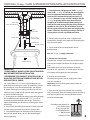
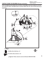
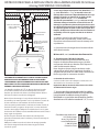
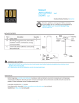
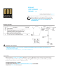
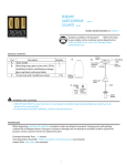
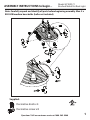
ASSEMBLY INSTRUCTIONS to begin...
Model # P1002-71
Brushed Nickel Pot Rack Light
Note: Carefully unpack and identify all parts before beginning assembly. Max. 2 x
R20 50W medium base bulbs (bulbs not included).
Supplied:
Decorative knob x 4
Decorative screw x 8
Questions? Call our customer service at 1800. 265. 9960
1
OVER 50lbs (22.68kg) . CHAIN SUSPENDED FIXTURE INSTALLATION INSTRUCTION
CEILING STRUCTURE MEMBER OR CROSS BRACE
CEILING WALL BOARD
CEILING JUNCTION BOX
SUPPLY WIRES
SUPPLY GROUND WIRE
HEXNUT
MOUNTING BAR
FIXTURE WIRES
MIN. 1/4" (6.35mm)
DIAMETER SCREW
THREADED PIPE
2. To hang fixtures weighing over 50 lbs. (22.68 kg.)
(over 25 lbs. (11.34 kg.) in Canada) the mounting bar
must be supported independently of the ceiling
junction box. Recommend minimum of two 1/4"
(6.35 mm) diameter screws or bolts (rated for 200 lbs.
(90.72 kg.) or greater) which must have sufficient
length to be installed through the mounting bar,
junction box, and securely into the ceiling structure
member or cross brace. This installation must be
able to support at least four times the weight of the
fixture. Check this fact before starting assembly. If
unsure please consult a qualified technician.
3. Fasten back two machine screws (supplied with
junction box) through slot at each end of mounting bar
and into junction box.
MACHINE SCREWS
4. Fasten another hex nut onto bottom end of
threaded pipe.
Min. 60 º C (140 º F) supply conductors
DECORATIVE KNOB
IMPORTANT:
-TURN POWER AT MAIN FUSE OR CIRCUIT BREAKER
BOX BEFORE STARTING INSTALLATION.
-RECOMMEND THIS PRODUCT BE INSTALLED BY A
QUALIFIED ELECTRICIAN TO REDUCE RISK OF FIRE
AND ELECTRICAL SHOCK.
1. A. Screw about 1/2" (12.70 mm) of threaded pipe into
center hole in mounting bar. Note: The protruding side lips
of mounting bar must face threaded pipe. See diagram.
B. Attach mounting bar to ceiling junction box with two
machine screws (supplied with junction box) through slot
at each end of mounting bar.
C. At this point test install the canopy onto ceiling through
this threaded pipe and make certain 5/16" (7.94 mm) of
threaded pipe protrude below the canopy. If not, then
adjust the threaded pipe location by screwing up or down
accordingly.
D. Once correct threaded pipe location has been adjusted,
remove canopy and mounting bar from junction box.
E. Lock threaded pipe into mounting bar by fastening a
hex nut from above. Note: Do not spin threaded pipe
during tightening.
5. Fixture wire connections:
Connect clear smooth side fixture wire to black supply
wire and clear ridged side fixture wire to white supply
wire.
Note: Make certain no loose conductors protrude
outside of wire connectors. And make certain all wires
are securely held together by wire connectors.
6. Ground wire connection:
Connect fixture ground wire to supply ground wire
with wire connector.
Important: Never connect ground wire to black or
white supply wires.
7. Once all wires are connected tuck, them carefully
into junction box. Then raise canopy against the ceiling
and lock into position by screwing decorative knob
onto the threaded pipe.
Checkolite International Inc.
142 Charles Street
Jersey City, NJ 07307
www.checkolite.com
1.800.265.9960
Printed in China
2
INSTRUCCIONES DE ENSAMBLAJE para comenzar...
Modelo N.° P1002-71
Lámpara para Estante de Ollas de
Níquel Cepillado
Nota: Desempaque con cuidado todas las piezas e identifíquelas antes de comenzar el ensamblaje. La lámpara utiliza 2 bombillas de base mediana R20 de 50 vatios como máximo (no incluye
bombillas).
Incluye:
Perillas decorativas x 4
Tornillos decorativos x 8
¿Preguntas? Llame a nuestro servicio al cliente al 1800. 265. 9960
1
INSTRUCCIONES PARA LA INSTALACIÓN DE UNA LÁMPARA DE MÁS DE 50 libras
(22.68 kg) SUSPENDIDA CON CADENA
BARRA DE MONTAJE
2. Para colgar lámparas que pesen más de 50 libras (22.68
kg.) (más de 25 libras (11.34 kg.) en Canadá) la barra de
montaje debe sostenerse independientemente de la caja
eléctrica del techo. Se recomienda un mínimo de dos
tornillos o pernos de 1/4" (6.35 mm) de diámetro
(clasificados para 200 libras (90.72kg.) o más) con un largo
suficiente como para instalarlos a través de la barra de
montaje, la caja eléctrica y dentro de la pieza de la estructura del techo o brazo transversal. Esta instalación deberá
ser capaz de soportar al menos cuatro veces el peso de la
lámpara. Verifique esta información antes de comenzar el
ensamblaje. Si no está seguro, consulte con un técnico
calificado.
TORNILLO DE 1/4” (6.35 mm)
DI ÁMETRO COMO MÍNIMO
DE
(NO INCLUIDO)
3. Vuelva a ajustar los dos tornillos para metal
(provistos con la caja eléctrica) a través de la ranura
ubicada en cada extremo de la barra de montaje en la
caja eléctrica.
PIEZA DE LA ESTRUCTURA DEL TECHO O BRAZO TRANSVERSAL
TABLA DE PARED DEL TECHO
CAJA ELÉCTRICA DEL TECHO
CABLES DE ALIMENTACIÓN
CABLE A TIERRA DE
ALIMENTACIÓN
TUERCA HEXAGONAL
CABLES DE LA LÁMPARA
TUBERÍA ROSCADA
DE 1/4" (6.35 mm)
TORNILLOS
PARA METAL
4. Ajuste otra tuerca hexagonal en el extremo inferior
de la tubería roscada.
Mínimo 60°C (140°F) conductores de alimentación.
PERILLA DECORATIVA
IMPORTANTE:
-DESCONECTE LA ENERGÍA DE LA CAJA DE FUSIBLES O CORTACIRCUITOS ANTES DE COMENZAR CON LA INSTALACIÓN
-SE RECOMIENDA QUE ESTE PRODUCTO SEA INSTALADO POR
UN ELECTRICISTA CALIFICADO PARA REDUCIR LOS RIESGOS DE
INCENDIO Y DESCARGA ELÉCTRICA.
1. A. Atornille alrededor de 1/2" (12.70 mm) de tubería roscada
en el orificio central de la barra de montaje. Nota: Los bordes
laterales que sobresalen de la barra de montaje deben ubicarse
de frente a la tubería roscada. Vea el diagrama.
B. Una la barra de montaje a la caja eléctrica del techo pasando
dos tornillos para metal (provistos con la caja eléctrica) a través de
la ranura ubicada en cada extremo de la barra de montaje.
C. En este punto pruebe instalar la cubierta en el techo a través de
la tubería roscada y asegúrese de que 5/16" (7.94 mm) de tubería
roscada sobresalga por debajo de la cubierta. De no ser así, ajuste
la ubicación de la tubería roscada atornillándola hacia arriba o hacia
abajo, según corresponda.
D. Una vez que la ubicación de la tubería roscada haya sido
ajustada correctamente, retire la cubierta y la barra de montaje de
la caja eléctrica.
E. Bloquee la tubería roscada en la barra de montaje ajustando
una tuerca hexagonal desde arriba. Nota: No gire la tubería
roscada al ajustar.
5. Conexiones de Cable de la Lámpara:
Conecte el cable transparente del lado liso de la
lámpara al cable de alimentación negro y el cable
transparente del lado con rebordes de la lámpara al
cable de alimentación blanco.
Nota: Asegúrese de que ningún conductor suelto
sobresalga por afuera de los conectores de cables. Y
asegúrese de que todos los cables estén sostenidos de
forma segura por los conectores de cable.
6. Conexión de cable a tierra:
Conecte el cable a tierra de la lámpara al cable a tierra de
alimentación con el conector de cable.
Importante: Nunca conecte el cable a tierra a los cables
de alimentación blanco o negro.
7. Una vez que haya conectado todos los cables,
introdúzcalos cuidadosamente en la caja eléctrica.
Luego levante la cubierta contra el techo y
bloquéela en su posición atornillando las perillas
decorativas en la tubería roscada de 1/4” (6.35 mm).
Checkolite International Inc.
142 Charles Street
Jersey City, NJ 07307
www.checkolite.com
1.800.265.9960
Printed in China
2