1
R
Protect 9XXX Series Wireless Alarm System
Instruction Manual
17.12.2012 en
Olympia Business Systems Vertriebs GmbH
Zum Kraftwerk 1
45527 Hattingen
Contents
Introduction . . . . . . . . . . . . . . . . . . . . . . . . . . . . . . . . . . . .
5
Operating Elements and Indicators . . . . . . . . . . . . . . 14
Warranty . . . . . . . . . . . . . . . . . . . . . . . . . . . . . . . . . . . . . . . . . . . . . . . . . .
5
Function Assignment to Buttons, Base Unit . . . . . . . . . . . . . . . . . . . . . 14
User Information . . . . . . . . . . . . . . . . . . . . . . . . . . . . . . . . . . . . . . . . . . .
5
Display Icons . . . . . . . . . . . . . . . . . . . . . . . . . . . . . . . . . . . . . . . . . . . . . . 15
Disclaimer of Liability . . . . . . . . . . . . . . . . . . . . . . . . . . . . . . . . . . . . . . . .
5
Overview of LEDs . . . . . . . . . . . . . . . . . . . . . . . . . . . . . . . . . . . . . . . . . . 16
Intended Use . . . . . . . . . . . . . . . . . . . . . . . . . . . . . . . . . . . . . . . . . . . . . .
5
Function Assignment to Buttons, Remote Control . . . . . . . . . . . . . . . . 16
Product Features . . . . . . . . . . . . . . . . . . . . . . . . . . . . . . .
6
Menu Structure . . . . . . . . . . . . . . . . . . . . . . . . . . . . . . . . . 17
Scope of Delivery . . . . . . . . . . . . . . . . . . . . . . . . . . . . . . .
6
Configuration . . . . . . . . . . . . . . . . . . . . . . . . . . . . . . . . . . 19
Safety Information . . . . . . . . . . . . . . . . . . . . . . . . . . . . . .
7
General Information . . . . . . . . . . . . . . . . . . . . . . . . . . . . . . . . . . . . . . . . . 19
Significance of the Symbols . . . . . . . . . . . . . . . . . . . . . . . . . . . . . . . . . .
7
Selecting the Language . . . . . . . . . . . . . . . . . . . . . . . . . . . . . . . . . . . . . . 19
Important Safety Information . . . . . . . . . . . . . . . . . . . . . . . . . . . . . . . . . .
7
Entry Code . . . . . . . . . . . . . . . . . . . . . . . . . . . . . . . . . . . . . . . . . . . . . . . . 19
GSM Telephone Dialling Unit . . . . . . . . . . . . . . . . . . . .
8
Setting the Date/Time . . . . . . . . . . . . . . . . . . . . . . . . . . . . . . . . . . . . . . . 20
Function of the GSM Telephone Dialling Unit . . . . . . . . . . . . . . . . . . . .
8
SIM Card . . . . . . . . . . . . . . . . . . . . . . . . . . . . . . . . . . . . . . . . . . . . . . . . . .
8
Unlocking the SIM Card . . . . . . . . . . . . . . . . . . . . . . . . . . . . . . . . . . . . .
8
Reminder Function . . . . . . . . . . . . . . . . . . . . . . . . . . . . . . . . . . . . . . . . .
9
Checking the Credit Status . . . . . . . . . . . . . . . . . . . . . . . . . . . . . . . . . . .
9
Preventing the SIM Card Being Locked . . . . . . . . . . . . . . . . . . . . . . . .
9
Individual Outgoing Messages . . . . . . . . . . . . . . . . . . . . . . . . . . . . . . . . 20
Activating the GSM Internal Telephone Dialling Unit with OGM Function .
21
Saving an SOS (Emergency Call) Number . . . . . . . . . . . . . . . . . . . . . . 22
Trigger Delay . . . . . . . . . . . . . . . . . . . . . . . . . . . . . . . . . . . . . . . . . . . . . . 23
Arming Delay . . . . . . . . . . . . . . . . . . . . . . . . . . . . . . . . . . . . . . . . . . . . . . 23
Alarm Period . . . . . . . . . . . . . . . . . . . . . . . . . . . . . . . . . . . . . . . . . . . . . . . 24
Installation . . . . . . . . . . . . . . . . . . . . . . . . . . . . . . . . . . . . . 10
Key Tone On/Off . . . . . . . . . . . . . . . . . . . . . . . . . . . . . . . . . . . . . . . . . . . 24
Information on Selecting the Installation Location . . . . . . . . . . . . . . . . 10
Setting the Display Contrast . . . . . . . . . . . . . . . . . . . . . . . . . . . . . . . . . . 24
Preparing and Connecting the Base Unit . . . . . . . . . . . . . . . . . . . . . . . 11
Remote Control . . . . . . . . . . . . . . . . . . . . . . . . . . . . . . . . . . . . . . . . . . . . 25
Testing the GSM Telephone Dialling Unit . . . . . . . . . . . . . . . . . . . . . . . 12
Flood and Smoke Detectors . . . . . . . . . . . . . . . . . . . . . . . . . . . . . . . . . . 25
Positioning the Base Unit . . . . . . . . . . . . . . . . . . . . . . . . . . . . . . . . . . . . 12
Overview of Monitoring Functions . . . . . . . . . . . . . . . 26
Wall Installation . . . . . . . . . . . . . . . . . . . . . . . . . . . . . . . . . . . . . . . . . . . . 13
OPERATING
INSTRUCTIONS
Giu
Page 3
Contents
Switching the Monitoring Functions On/Off . . . . . . 26
Information on Disposal . . . . . . . . . . . . . . . . . . . . . . . . 34
Alarm Mode . . . . . . . . . . . . . . . . . . . . . . . . . . . . . . . . . . . . . . . . . . . . . . . 27
Technical Data . . . . . . . . . . . . . . . . . . . . . . . . . . . . . . . . . 35
At Home Mode . . . . . . . . . . . . . . . . . . . . . . . . . . . . . . . . . . . . . . . . . . . . . 27
Base Unit . . . . . . . . . . . . . . . . . . . . . . . . . . . . . . . . . . . . . . . . . . . . . . . . . 35
Silent Mode . . . . . . . . . . . . . . . . . . . . . . . . . . . . . . . . . . . . . . . . . . . . . . . . 27
Remote Control . . . . . . . . . . . . . . . . . . . . . . . . . . . . . . . . . . . . . . . . . . . . 35
Disarmed Mode . . . . . . . . . . . . . . . . . . . . . . . . . . . . . . . . . . . . . . . . . . . . 28
Technical Modifications . . . . . . . . . . . . . . . . . . . . . . . . . . . . . . . . . . . . . . 35
Panic Alarm . . . . . . . . . . . . . . . . . . . . . . . . . . . . . . . . . . . . 28
CE Mark . . . . . . . . . . . . . . . . . . . . . . . . . . . . . . . . . . . . . . . 36
Emergency Call (SOS) . . . . . . . . . . . . . . . . . . . . . . . . . . 28
Remote Access Via Telephone . . . . . . . . . . . . . . . . . . 29
Resetting the Factory Settings (RESET) . . . . . . . . . . 30
Registering Sensors . . . . . . . . . . . . . . . . . . . . . . . . . . . . 31
Deregistering Sensors . . . . . . . . . . . . . . . . . . . . . . . . . . 31
System Extension . . . . . . . . . . . . . . . . . . . . . . . . . . . . . . 31
Changing the Batteries . . . . . . . . . . . . . . . . . . . . . . . . . . 32
Remote Control . . . . . . . . . . . . . . . . . . . . . . . . . . . . . . . . . . . . . . . . . . . . 32
Base Unit . . . . . . . . . . . . . . . . . . . . . . . . . . . . . . . . . . . . . . . . . . . . . . . . . 32
Regular Maintenance and Servicing . . . . . . . . . . . . . . 33
Base Unit . . . . . . . . . . . . . . . . . . . . . . . . . . . . . . . . . . . . . . . . . . . . . . . . . 33
Page 4
Giu
OPERATING
INSTRUCTIONS
Introduction
User Information
Introduction
Warranty
Dear Customer,
we are pleased that you have chosen this equipment.
In the case of a defect, please return the device together with the receipt
and original packing material to the point-of-sale.
The alarm system is a passive security product and has been conceived
as a deterrent. Additional measures are necessary to prevent and hinder
burglary and theft. You can obtain all the necessary information on this
from your local police station.
Read the operating instruction manual thoroughly before connecting and
starting the system for the first time. The operating instruction manual will
help prevent application errors and, at the same time, ensure you can ex
ploit all the technical options provided by the wireless alarm system to the
full.
Disclaimer of Liability
We cannot guarantee that the information which relates to the technical
properties of the product or to the product itself contained in this document
is correct. The product and its accessories described in this document are
subject to constant improvement and further development. For this reason,
we reserve the right to modify components, accessories, technical specific
ations and related documentation of the product described herein at any
time without notice.
Intended Use
The wireless alarm systems from the Protect 9XXX-Series enable you to
monitor rooms and buildings as long as the local conditions are such that
they enable a reliable transmission link to the sensors (e.g. door/window
contact, smoke detector). In addition, all doors and windows must be
equipped with door/window contacts. A condition for complying with the
intended use is that the equipment is installed correctly and the information
in this operating instruction manual is observed and maintained.
Any other use is considered unintended use. Unauthorised modifications or
reconstructions not described in this operating instruction manual are not
permitted and could cause the product to be damaged. Furthermore, risks
through short-circuits, fire, electric shock etc. cannot be ruled out.
OPERATING
INSTRUCTIONS
Giu
Page 5
Product Features / Scope of Delivery
Product Features
S
S
S
S
S
S
S
S
S
S
S
S
S
S
S
Scope of Delivery
Wireless alarm system with emergency call, panic, screening and
handsfree functions.
Transmit function to activate outdoor sirens etc.
Integrated GSM telephone dialling unit with outgoing message for
alarm messages via the mobile network.
Base unit
1
Power adapter plug
1
Remote control
1
Up to 10 alarm call numbers and 1 emergency call number (SOS)
can be stored.
Batteries
Messages for alarm calls can be set up individually for each re
spective sensor, up to max. 10 seconds long.
Assembly material
3x alkaline AAA
1x lithium CR2430 3 V
Operating instructions
Automatic dialling of the next number when the number called is
"engaged".
Handsfree function on the base unit in the case of an SOS.
Telephone (silent) alarm/siren alarm can be set individually or com
bined.
Screws, dowels, adhesive tape
1
Please check the contents of the package carefully. If anything is missing
or has been damaged during transport, DO NOT put the wireless alarm
system into operation! In such cases, contact your sales outlet, with your
purchase receipt to hand, or the OLYMPIA service centre.
Large LC display, 1 numeric line in 7 segments for 24 characters,
1 alphanumeric line in 5x7 dot matrix for 13 characters, 11 icons as
status indicators.
Display lighting in yellow and blue.
Warning in the event of a low battery charge status (base unit and
all registered sensors).
NOTE:
Keep the packaging in a safe place to protect
the equipment from damage should it need to
be dispatched in future.
NOTE:
This operating instruction manual relates to
the base unit of the alarm system. The sensors
are described in separate manuals.
Power failure backup in the base unit.
Base unit has a remote control facility.
Upgradable for operation with max. 32 sensors.
Simple integration of new sensors/smoke detectors, Plug-and-Play.
Page 6
Giu
OPERATING
INSTRUCTIONS
Safety Information
Safety Information
Important Safety Information
Significance of the Symbols
Please observe the following safety information to ensure the wireless
alarm system can be used safely and reliably:
WARNING:
CAUTION:
NOTE:
Indicates potentially dangerous situations
which could lead to fatal or severe personal
injury if the information is ignored.
Indicates potentially dangerous situations
which could lead to minor personal injury if the
information is ignored.
Indicates potentially dangerous situations
which could lead to property or environmental
damage if the information is ignored.
S
S
S
S
S
S
If you are uncertain or have any doubts about the functioning
method of the equipment during assembly and installation, contact
a specialist. In case of doubt, do not complete assembly and install
ation work yourself.
Never open the equipment! Never use the device when it is wet or
in the vicinity of a bathtub, shower or such!
Repairs to defective equipment must always be completed by au
thorised service technicians.
Never touch the power adapter plug on the base unit with wet or
damp hands.
If the power adapter plug shows signs of damage, disconnect the
fuse in the fuse box prior disconnecting the relevant plug from the
power socket.
The wireless alarm system and packaging materials must not be
used as toys by children.
NOTE:
OPERATING
INSTRUCTIONS
Giu
This operating instruction manual contains
important information on setting up and hand
ling the equipment. The manual must be en
closed with the equipment if handed over to
others.
Page 7
GSM Telephone Dialling Unit
GSM Telephone Dialling Unit
Unlocking the SIM Card
Function of the GSM Telephone Dialling Unit
SIM cards are normally locked against unauthorised use by means of a
4-digit PIN.
The GSM telephone dialling unit (dual band, 900/1800 MHz) establishes a
connection between the Protect 9XXX-Series alarm system and mobile
network. It enables a telephone link to be set up without access to a land
line.
SIM Card
(not included in equipment supplied)
In order to operate the GSM telephone dialling unit you need a SIM card
from a mobile phone provider. This is not included in the equipment sup
plied.
NOTE:
The alarm system can also be operated without
a SIM card connection. However, in the event
of an alarm, there is no alert via the mobile net
work!
If you use a prepaid card, pay attention to the following:
S
S
When the SIM card is used for the first time, it must be unlocked.
1. If the SIM card is locked against use by a PIN, SIM Card PIN? ap
pears in the display.
2. Enter the PIN received together with the SIM card.
3. When the PIN has been entered correctly, Search… appears in the
display.
The PIN is then permanently deactivated. If you insert the SIM card again
or connect the base unit again, the PIN need not be entered.
S
S
S
If you enter the PIN incorrectly, Enter again appears in the display.
If you enter the PIN incorrectly 3 times, SIM Locked appears in the
display. In this case, contact your mobile phone provider to unlock
the SIM card.
If the SIM card inserted is not a GSM card, SIM Error appears in
the display.
The card must be topped up at regular intervals.
Most prepaid cards must be used at a charge within a certain
period of time, otherwise they are blocked. Contact your mobile
phone provider for details regarding deadlines.
Page 8
Giu
OPERATING
INSTRUCTIONS
GSM Telephone Dialling Unit
Reminder Function
Preventing the SIM Card Being Locked
Check SIM $ appears in the display on 31st March, 30th June,
30th September and 31st December.
Most prepaid cards must be used at a charge within a certain period of
time, otherwise they are blocked. You can use the function requesting the
credit status to make a call liable for costs.
Checking the Credit Status
NOTE:
4. When the Check SIM $ reminder message appears, enter the
device-specific Entry Code. Confirm it by pressing .
5. SIM Service # appears in the display.
6. Enter the service number of the mobile phone provider. Confirm it by
pressing . The service number is dialled.
7. Follow the instructions from the mobile phone provider.
8. Press to end the call.
You can request the credit status at any time by using the menu.
Enter the device-specific Entry Code. Confirm it by pressing .
The menu is opened by pressing the Menu button briefly.
Select the Check SIM $ menu option. Confirm it by pressing .
SIM Service # appears in the display.
Enter the service number of the mobile phone provider. Confirm it by
pressing . The service number is dialled.
6. Follow the instructions from the mobile phone provider.
7. Press to end the call.
1.
2.
3.
4.
5.
OPERATING
INSTRUCTIONS
Contact your mobile phone provider for details
regarding time limits within which prepaid
cards must be used.
Enter the device-specific Entry Code. Confirm it by pressing .
The menu is opened by pressing the Menu button briefly.
Select the Check SIM $ menu option. Confirm it by pressing .
SIM Service # appears in the display.
Enter the number of your conventional phone or mobile phone.
Confirm it by pressing . The number is dialled.
6. Take the call on your conventional phone or mobile phone.
7. Press to end the call.
1.
2.
3.
4.
5.
Giu
Page 9
Installation
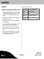
Examples of sources of interference
Installation
Information on Selecting the Installation Location
S
S
S
S
S
S
The base unit should be installed or positioned in a central location
(e.g. in the hallway of an apartment/house) in relation to the area to
be monitored in order to keep all transmission paths as short as
possible.
Place the base unit in a location where a properly installed power
socket (230 V / 50 Hz) is available.
Metallic objects
Source of electrical interference
Radiators
Loudspeaker systems
Mirrors
Motors
Concrete steel
walls
Unshielded electrical apparatus
Metal doors
Ensure that the base unit can receive a sufficiently powerful signal
from the mobile network.
Choose a location within the area being monitored to ensure that no
intruders can approach the base unit and manipulate it.
The base unit and power adapter plug must not be used in damp
rooms (cellar, bathroom, etc.) or in the direct vicinity of sources of
heat.
The base unit should not be installed/setup on or in the direct vicin
ity of large metallic objects or sources of electrical interference be
cause this reduces the transmission range.
Page 10
Giu
OPERATING
INSTRUCTIONS
Installation
6. Insert three AAA alkaline batteries in the battery compartment (pay
attention to correct polarity).
7. If the alarm system is to be operated without the external antenna
(option), the antenna switch must be switched to the left and set to
Int.
Preparing and Connecting the Base Unit
Power socket
Ext. Ant
DC 6 V "
RESET
Int
Ext
Antenna
switch
RESET
"
Power
adapter plug
Ext. Ant
SIM card
DC 6V
Antenna switch
RESET
OPERATING
INSTRUCTIONS
LOCK
Int
Ext
8. Connect the power adapter plug to the base unit.
9. Replace the lid on the battery and connection socket compartment.
10. Replace and tighten the screw.
OPEN
LOCK
OPEN
1. Use a screwdriver to loosen the screw in the battery and connection
socket compartment on the underside of the base unit.
2. Remove the lid from the battery and connection socket compartment.
3. Slide the SIM card holder to the left to unlock it (A).
4. Pivot the holder up and insert the SIM card in the holder (B).
5. Pivot the holder with the SIM card back and slide the holder to the
right to lock it (C)
A
B
C
Giu
Page 11
Installation
Testing the GSM Telephone Dialling Unit
NOTE:
Positioning the Base Unit
Test the GSM telephone dialling unit to ensure
that the alarm function is activated via the mo
bile network.
Enter the device-specific Entry Code. Confirm it by pressing .
The menu is opened by pressing the Menu button briefly.
Select the Check SIM $ menu option. Confirm it by pressing .
SIM Service # appears in the display.
Enter the number of your conventional phone or mobile phone.
Confirm it by pressing . The number is dialled.
6. Take the call on your conventional phone or mobile phone.
7. Press to end the call.
1.
2.
3.
4.
5.
Page 12
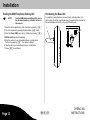
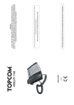
It is possible to setup the device in a user-friendly, inclined position on a
table or desk. To do this, insert the two legs (1) supplied in the recesses for
the wall installation bracket (2) on the rear of the base unit.
1
Giu
2
OPERATING
INSTRUCTIONS
Installation
Wall Installation
After having found a suitable location for the base unit, you can begin with
the installation.
WARNING:
NOTE:
Risk of fatal injury through electric shock or
gas explosion. Pay attention that you do not
damage electric cables or gas pipes.
Also pay attention to water pipes.
1. At the installation location, insert two screws in the wall, 100 mm
apart and aligned horizontally. (It may be necessary to drill the holes
first and then insert dowels in which to tighten the screws, depending
on the properties of the wall.)
2. Screw the screws in the wall using a screwdriver until there is approx.
3 mm clearance from the bottom edge of the screw head to the wall.
3. Hook the base unit over the screws.
4. Connect the power adapter plug to a properly installed 230 V / 50 Hz
power socket. The base unit is then ready to use.
OPERATING
INSTRUCTIONS
Giu
Page 13
Operating Elements and Indicators
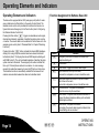
Function Assignment to Buttons, Base Unit
Operating Elements and Indicators
The base unit is equipped with an SOS (emergency call) button for emer
gency situations and a Panic button in the event of a direct threat. The
wireless remote control unit is provided with a button which can be con
figured either as an Emergency Call or Panic button (refer to Configuring
the Wireless Remote Control Unit).
Pressing the Panic button triggers an immediate acoustic signal,
intended as a deterrent, regardless of whether the alarm system is active
or inactive. The acoustic alarm can be switched off via the base unit or the
wireless remote control (refer to "Disarmed Mode" in Chapter "Monitoring
Functions").
Pressing the button button activates the internal GMS telephone
dialling unit, as long as phone numbers have been entered and stored
beforehand (refer to "Configuring the internal GMS telephone dialling unit
with OGM function"). The unit is activated regardless of whether the alarm
system is armed or disarmed. The emergency call number is dialled first,
then up to 10 stored phone numbers in succession . A voice message
requests the subscriber answering to press the [1] button on their phone.
The handsfree function is automatically activated on the base unit and
enables communication between the caller and subscriber called.
Page 14
Button
Function
Emergency Call button: Activates the internal GSM
telephone dialling unit
Confirmation
Panic button: Triggers an acoustic alarm signal
Open the menu; scroll up in the menu;
increase the loudspeaker volume in Handsfree mode
Open the Location Key function for phone numbers;
scroll down in the menu;
reduce the loudspeaker volume in Handsfree mode
Disarmed mode: The system is deactivated;
close the menu; stop the countdown
Silent mode: The system is armed; when the alarm is
tripped, the internal telephone dialling unit is activated;
delete digits and letters
Alarm mode: The system is activated;
on burglary, the acoustic alarm signal and internal tele
phone dialling unit are activated
Giu
OPERATING
INSTRUCTIONS
Operating Elements and Indicators
At Home mode: The system is activated;
on burglary: the acoustic alarm signal is issued
0-9, *, #
Digit keys: On pressing the # button >3 sec., a 2 sec.
dialling pause is activated
*
In Text mode: Switch between upper and lower case
#
àáâÇ
0
+&@0/%*#$£O§¿¡
1
Space - ? ! 1 , . : ; “ ' < = > ( ) { }_
2
ABC2ÄÆÅàáâÇ
abc2äæåàáâç
3
DEF3èÉêë
def3èéêë
4
GHI4ìíîÏ
ghi4ìíîï
5
JKL5€
jkl5€
6
MNO6ñöòóô
mno6ñöòóô
7
PQRS7ß
pqrs7ß
8
TUV8ùúûÜ
tuv8ùúûü
9
WXYZ9
wxyz9
OPERATING
INSTRUCTIONS
Display Icons
Icon
Significance
Explanation
Mobile network
full signal,
weak signal,
no signal
Silent mode
If an alarm is triggered, no acoustic
alarm is issued; internal GSM tele
phone dialling unit is activated.
Alarm mode
If an alarm is triggered, an acoustic
alarm is issued; internal GSM tele
phone dialling unit is activated.
At Home Mode
If an alarm is triggered, an acoustic
alarm is issued.
SOS
Emergency call
Internal GSM telephone dialling unit
is activated.
a
Time delay
Time delay is activated.
Key lock
Key lock is activated.
Internal GSM
telephone dialling
unit activated.
Connection is being made.
Recording mode
Voice message is being recorded.
Giu
Page 15
Operating Elements and Indicators
Memory locationdisplay.
h
Save icon
Battery indicator
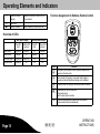
Function Assignment to Buttons, Remote Control
Indicates the memory location of the
phone number.
Battery capacity of base unit is low.
Overview of LEDs
With power supply
Top LED
(red)
Bottom LED
(yellow)
Silent mode
Lights up
Alarm mode
Flashes
At Home mode
Inactive mode
Without power supply
Top LED
(red)
Bottom LED
(yellow)
Flashes
Off
Flashes
Off
Flashes
Off
Lights up
Lights up
Off
Lights up
Lights up
Off
Off
Off
Button
Emergency call or panic function (can be optionally con
figured on the base unit)
Alarm mode: On burglary, an acoustic alarm signal is
issued and internal telephone dialling unit is activated
Page 16
Function
Giu
At Home mode: On burglary, an acoustic alarm is issued
Deactivate key lock on base unit;
Stop alarm signal;
Switch alarm system inactive.
Silent mode activated on pressing the Alarm and At
Home mode buttons simultaneously.
OPERATING
INSTRUCTIONS
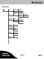
Menu Structure
Menu Structure
Review
Register
Trigger Delay
Open Sensor01
Voice Record
Remote:1
Voice Record
Search…
Open Sensor01
Voice Record
Remote:1
Voice Record
Duration
Delay: 0-240S
Trigger Tone
On
Off
Arming Delay
Delay: 0-240S
Flood & Smoke
Standard
Activate
Remote Key
Remote: SOS
Remote: PANIC
Entry Code
OPERATING
INSTRUCTIONS
1234
Giu
Page 17
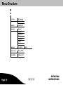
Menu Structure
Key Tone
Key Tone-On
Key Tone-Off
Contrast
Contrast-1-5
Language
Deutsch
Español
Nederlands
Dansk
Português
English
Français
Page 18
Date/Time
01-01-2010
Alarm period
Time:1-10Min
Check SIM $
SIM Service #
00:00
Giu
OPERATING
INSTRUCTIONS
Configuration
Selecting the Language
Configuration
There is a range of languages available for selection:
General Information
NOTE:
Before beginning to operate the base unit, de
activate the key lock function. You need the
4-digit Entry Code to do this. The default,
device-specific Entry Code is provided in the
battery compartment of the base unit.
The key lock is reactivated automatically when no buttons are pressed for
a period of 10 seconds. You can also activate the key lock function manu
ally by pressing the button.
The SOS and Panic buttons are excluded from the key lock function and
are always functional!
Operation:
S
S
The menu is opened by pressing the Menu button briefly.
S
Confirm selections and entries by pressing the button. If
values are set in certain menus, they are accepted and saved.
S
S
S
Navigate through the menu using the arrow buttons and
.
Text or numbers which have been entered can be corrected by
pressing the button.
Enter the device-specific Entry Code. Confirm it by pressing .
The menu is opened by pressing the Menu button briefly.
Select the Language menu option. Confirm it by pressing .
Select the language required by pressing the and buttons.
5. Confirm it by pressing . The main menu reappears in the
display.
6. Close the menu by pressing the button.
1.
2.
3.
4.
Entry Code
Proceed as follows to change the Entry Code:
1. Enter the device-specific Entry Code. Confirm it by pressing .
2. The menu is opened by pressing the Menu button briefly.
3. Select the Entry Code menu option. Confirm it by pressing .
The default Entry Code appears in the display. The first digit flashes.
Enter the 4-digit Entry Code.
4. Note your individual Entry Code down and keep it in a safe place.
5. Confirm it by pressing . The main menu reappears in the
display.
6. Close the menu by pressing the button.
Press the button briefly to move one menu level back.
If no button is pressed for a period of 10 seconds, the menu is auto
matically closed and the key lock activated.
OPERATING
INSTRUCTIONS
Giu
Page 19
Configuration
Setting the Date/Time
1.
2.
3.
4.
5.
6.
7.
8.
9.
Enter the device-specific Entry Code. Confirm it by pressing .
The menu is opened by pressing the Menu button briefly.
Select the Date/Time menu option. Confirm it by pressing .
Display: 01-01-2010.
Use the keypad on the base unit to enter the day, month and year.
Confirm it by pressing .
Display: 00:00.
Enter the time as hour and minute.
Confirm it by pressing . The main menu reappears in the
display.
Close the menu by pressing the button.
3. Select the Review menu option. Confirm it by pressing .
4. Select the respective sensor required by pressing the and
buttons. Confirm it by pressing .
5. The first letter of the sensor selected flashes. You can rename the
sensor (e.g. BalconyDoor, KitchenWindow, etc.). Confirm it by press
ing .
6. Text or numbers which have been entered can be deleted by press
ing the button.
7. Voice Record appears in the display. Confirm it by pressing
.
8. Speak your individual voice message for the selected sensor into the
unit (e.g. BalconyDoor).
9. Press the button to confirm the message and end recording.
NOTE:
Individual Outgoing Messages
NOTE:
You can record an individual message of up to
max. 10 seconds for each sensor (door/window
contact, smoke detector). The standard mes
sage is replaced by your individual voice mes
sage and played when the GSM telephone dial
ling unit is activated!
If you do not confirm it by pressing the button, recording is automatically ended after
10 seconds.
10. Your individual voice message is played back. The main menu re
appears in the display.
11. Close the menu by pressing the button.
Proceed as follows to record an individual messages for each respective
sensor:
1. Enter the device-specific Entry Code. Confirm it by pressing .
2. The menu is opened by pressing the Menu button briefly.
Page 20
Giu
OPERATING
INSTRUCTIONS
Configuration
Activating the GSM Internal Telephone Dialling
Unit with OGM Function
NOTE:
A SIM card must be installed in order to use
the GSM telephone dialling unit.
The internal telephone dialling unit is deactivated if no telephone numbers
have been entered and saved.
You can enter up to 10 individual telephone or mobile phone numbers of
contact persons, such as relatives, friends or neighbours. In the event of
an alarm, the internal GSM telephone dialling unit dials these phone num
bers automatically in the sequence they were entered (beginning with
memory location 0) and communicates the status via the voice messages
assigned to the respective sensors. In the case of an "engaged" signal or
no connection is possible, the next phone number is automatically dialled.
A total of three dialling cycles are completed!
The internal GMS telephone dialling unit is deactivated when a subscriber
called answers the call made and presses the numeric key [1] on his tele
phone or 3 dialling cycles have been completed.
NOTE:
Save as many phone numbers as possible.
This increases the probability of reaching a
contact person in the event an alarm is
triggered. If, for example, you only save two
phone numbers and both are engaged when
the alarm call is sent, the dialling cycle soon
comes to an end!
NOTE:
Do not forget to inform the contact persons
that they will be called by your alarm system
automatically if an alarm is triggered and agree
on a sequence of actions if the alarm is
triggered.
OPERATING
INSTRUCTIONS
Memory locations 0-9 (buttons to ) are available to enter up
to 10 phone numbers. Each phone number can be composed of up to 24
characters/digits. In addition, a name with up to 13 characters/letters can
be assigned to each phone number.
NOTE:
Unjustified requests for police, fire and rescue
services are liable for costs!
Save the phone numbers as follows:
1. Enter the device-specific Entry Code. Confirm it by pressing .
2. Press the button. Location Key appears in the display.
3. Select a memory location (button -). If you have not
yet stored a phone number, Empty appears as information in the
display. Confirm it by pressing .
4. Enter the phone number including the access code. Confirm it by
pressing .
5. Enter the name associated with the phone number. Confirm it by
pressing .
6. Press to exit from the menu.
Giu
Page 21
Configuration
After having entered phone numbers, ensure that they are correct in re
spect of the alarm calls. You can do this by triggering a silent alarm. The
telephone numbers you have entered are dialled in succession in the pro
grammed sequence.
1. Enter the device-specific Entry Code. Confirm it by pressing .
2. On pressing the key, Silent mode is activated. Silent mode is
indicated in the display by the icon after the selected arming delay
has expired.
3. Now trip the silent alarm on any of the door/window contacts (e.g.
open door/window).
NOTE:
When Silent mode is active, there is no acous
tic alarm signal. The display lights up yellow
and indicates which sensor has been triggered.
The internal GSM telephone dialling unit is ac
tivated after the trigger delay has expired.
S The subscriber called takes the call and the individual message
recorded for the sensor triggered is played.
S The subscriber called is also requested to press digit key [1] on
their telephone. The screening function is activated. This function
enables the subscriber to screen the room in which the base unit is
located.
S If the subscriber called does not initiate a function within 24
seconds, the next phone number is automatically dialled.
S Silent mode is deactivated by pressing the button on the re
mote control, entering your Entry Code on the base unit and con
firming by pressing the button or when the subscriber
called ends the call.
Page 22
Saving an SOS (Emergency Call) Number
You can save an SOS (emergency call) number which is subsequently
called first by pressing the button on the base unit or, depending
on the configuration, the button on the remote control. Following this
number, the other phone numbers stored, maximally 10, are called in suc
cession (refer to "Activating the Internal Telephone Dialling Unit with OGM
Function").
Save the SOS number as follows:
NOTE:
Unjustified requests for police, fire and rescue
services are liable for costs!
1. Enter the device-specific Entry Code. Confirm it by pressing .
2. Press the button. Location Key appears in the display.
3. Press the button as the selected memory location. If you
have not yet stored a phone number, Empty appears as information
in the display. Confirm it by pressing .
4. Enter the phone number including the access code. Confirm it by
pressing .
5. Enter the name associated with the phone number. Confirm it by
pressing .
6. Press to exit from the menu.
Giu
OPERATING
INSTRUCTIONS
Configuration
Trigger Delay
Arming Delay
The alarm is triggered after a delay so that if someone enters through the
main door, they can disarm the alarm system before the acoustic alarm
signals and internal GSM telephone dialling unit are activated. You can set
a trigger delay between 0 and 240 seconds.
You can set an activation delay between 0 and 240 seconds. The alarm
system is armed after this period has expired. You must leave your apart
ment/house within this period through the door which will subsequently be
monitored. An acoustic signal is issued by the base unit every second for
the period of the set delay time.
If one of the sensors is tripped, the system must be switched to be dis
armed for this period so that no alarm is triggered.
You can select whether an acoustic signal should be issued from the base
unit during this period or not.
1. Enter the device-specific Entry Code. Confirm it by pressing .
2. The menu is opened by pressing the Menu button briefly.
3. Select the Trigger Delay menu option. Confirm it by pressing
.
4. Select the Duration menu option. Confirm it by pressing .
5. Use the and buttons to set the required delay time.
6. Confirm it by pressing the button. The system returns to the
previous menu level.
7. Select the Trigger Tone menu option. Confirm it by pressing
.
8. Use the and buttons to select Off or On.
9. Confirm it by pressing the button. The system returns to the
previous menu level.
10. Press to exit from the menu.
OPERATING
INSTRUCTIONS
1. Enter the device-specific Entry Code. Confirm it by pressing .
2. The menu is opened by pressing the Menu button briefly.
3. Select the Arming Delay menu option. Confirm it by pressing
.
4. Use the and buttons to set the required delay time.
5. Confirm it by pressing . The main menu reappears in the
display.
6. Press to exit from the menu.
Giu
Page 23
Configuration
Alarm Period
Key Tone On/Off
The base unit is equipped with an integrated siren. The duration of the
acoustic alarm can be selected between a minimum of 1 minute to a max
imum of 10 minutes. The alarm period is preset to 3 minutes (an alarm
period up to 3 minutes is permitted in Germany).
It is possible to switch the key tone feature for the base unit on and off:
1. Enter the device-specific Entry Code. Confirm it by pressing .
2. The menu is opened by pressing the Menu button briefly.
3. Select the Alarm period menu option. Confirm it by pressing
.
4. Use the and buttons to set the required alarm period.
5. Confirm it by pressing . The main menu reappears in the
display.
6. Press to exit from the menu.
Enter the device-specific Entry Code. Confirm it by pressing .
The menu is opened by pressing the Menu button briefly.
Select the Key Tone menu option. Confirm it by pressing .
Use the and buttons to select the Key Tone-On or
Key Tone-Off function.
5. Confirm it by pressing . The main menu reappears in the
display.
6. Press to exit from the menu.
1.
2.
3.
4.
Setting the Display Contrast
The display contrast can be adjusted to one of five different settings:
Enter the device-specific Entry Code. Confirm it by pressing .
The menu is opened by pressing the Menu button briefly.
Select the Contrast menu option. Confirm it by pressing .
Use the and buttons to adjust the contrast according
to your needs.
5. Confirm it by pressing . The main menu reappears in the
display.
6. Press to exit from the menu.
1.
2.
3.
4.
Page 24
Giu
OPERATING
INSTRUCTIONS
Configuration
Remote Control
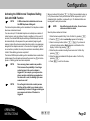
Flood and Smoke Detectors
You can set-up the base unit so that flood and smoke detectors trigger an
alarm when the base unit is disarmed.
1. Enter the device-specific Entry Code. Confirm it by pressing .
2. The menu is opened by pressing the Menu button briefly.
3. Select the Flood & Smoke menu option. Confirm it by pressing
.
4. Use the and buttons to select Standard or Activate.
5. Confirm it by pressing . The main menu reappears in the
display.
6. Press to exit from the menu.
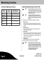
The table below indicates how the flood and smoke detectors are triggered
according to the various settings.
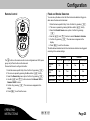
The button on the remote control can be configured as an SOS (emer
gency call) or Panic button via the base unit.
Proceed as follows to configure the button:
Enter the device-specific Entry Code. Confirm it by pressing .
The menu is opened by pressing the Menu button briefly.
Select the Remote Key menu option. Confirm it by pressing .
Use the and buttons to select the Remote: SOS or
Remote: PANIC function.
5. Confirm it by pressing . The main menu reappears in the
display.
6. Press to exit from the menu.
1.
2.
3.
4.
OPERATING
INSTRUCTIONS
Standard
Activate
Phone call
Alarm signal
Phone call
Alarm signal
Disarmed
mode
No
No
Yes
Yes
At Home
Mode
No
Yes
No
Yes
Silent mode
Yes
No
Yes
Yes
Alarm mode
Yes
Yes
Yes
Yes
Giu
Page 25
Monitoring Functions
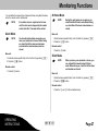
Overview of Monitoring Functions
Switching the Monitoring Functions On/Off
NOTE:
Monitoring
function
Acoustic
alarm signal
Internal GSM telephone
dialling unit activated.
Silent mode
No
Yes with screening function
Alarm mode
Yes
Yes
At Home mode
Yes
No
Disarmed mode
No
No
Emergency call
(SOS)
No
Yes with handsfree function
Panic alarm
Yes
No
NOTE:
The alarm period of the acoustic alarm is re
stricted from a minimum of 1 minute to a max
imum of 10 minutes depending on the config
uration.
The wireless alarm system distinguishes between 4 types of alarm:
1. Alarm mode
When Alarm mode is active and an alarm is triggered, an acoustic
alarm signal is issued and the internal GSM telephone dialling unit is
activated.
2. At Home mode
When At Home mode is active and an alarm is triggered, only an
acoustic alarm signal is issued.
3. Silent mode
When Silent mode is active and an alarm is triggered, only the intern
al GSM telephone dialling unit is activated. A message requests the
subscriber called to press the [1] button on their phone/mobile. The
screening function is activated.
4. Disarmed mode
When Disarmed mode is set, the alarm system is deactivated.
The monitoring functions are confirmed by a voice message.
NOTE:
Page 26
Before switching any functions on, inform all
the other people living in the residence regard
ing the location and method of operation of the
wireless alarm system.
Giu
When triggered, the smoke detector always
issues an acoustic alarm signal (immediately)
regardless of the wireless alarm system! The
response of the base unit depends on the type
of alarm and setting defined in the
Flood & Smoke menu option.
OPERATING
INSTRUCTIONS
Monitoring Functions
You can define the required type of alarm as follows using either the base
unit or the remote control unit supplied:
NOTE:
NOTE:
If an outdoor siren is registered on the base
unit, the alarm can be stopped by the remote
control unit after 15 seconds at the earliest.
During the night, when you are asleep, you
should activate At Home mode. Before doing
so, check that all the doors and windows are
closed.
Base unit
Alarm Mode
NOTE:
At Home Mode
You should activate Alarm mode when you
leave your apartment or house. Before doing
so, check that all the doors and windows
provided with a door/window contact are
closed.
Base unit
1. Enter the device-specific Entry Code. Confirm it by pressing .
2. Press the button.
1. Enter the device-specific Entry Code. Confirm it by pressing .
2. Press the button.
Remote control
1. Press the button.
Silent Mode
NOTE:
Remote control
1. Press the button.
When you leave your apartment or house, you
can activate Silent mode instead of Alarm
mode. Before doing so, check that all the doors
and windows are closed.
Base unit
1. Enter the device-specific Entry Code. Confirm it by pressing .
2. Press the button.
Remote control
1. Press the and buttons simultaneously.
OPERATING
INSTRUCTIONS
Giu
Page 27
Monitoring Functions
Disarmed Mode
NOTE:
Emergency Call (SOS)
When alarm system is disarmed, you can move
freely within the living quarters without trigger
ing any alarms.
Base unit
1. Enter the device-specific Entry Code. Confirm it by pressing .
Remote control
1. Press the button.
You can trigger the SOS (emergency call) function by pressing the button on the base unit or the button on the remote control unit, de
pending on the configuration. The internal GSM telephone dialling unit is
automatically activated when phone numbers have been stored. The emer
gency call number is dialled first, then up to 10 stored phone numbers in
succession. A message requests the subscriber called to press the [1]
button on their phone/mobile. The handsfree function is automatically activ
ated and enables communication between the caller and subscriber called.
There are three ways to end the SOS function:
a) Enter your 4-digit Entry Code on the base unit and confirm it
by pressing the button.
b) Press the button on the remote control.
c) The subscriber called takes the call, executes a function with
in 24 seconds (refer to "Activating the Internal Telephone
Dialling Unit with OGM Function") and then ends the call.
Panic Alarm
You can activate a panic alarm as a deterrent by pressing the button on the base unit or the button on the remote control unit, de
pending on the configuration. The panic alarm is triggered immediately
without any delay.
To switch off the panic alarm, enter your 4-digit Entry Code on the base
unit. Confirm it by pressing . Or, you can press the button on
the remote control.
Page 28
Giu
OPERATING
INSTRUCTIONS
Remote Access Via Telephone
Remote Access Via Telephone
Key
The wireless alarm system can be operated by remote access using a
telephone. You can use a telephone to activate or deactivate the alarm
system and switch the handsfree and screening functions on.
Proceed as follows to operate your alarm system by remote access using
a telephone:
1. Dial the mobile phone number of the SIM card installed in the alarm
system.
2. Wait until the alarm system takes the call following the eighth ring.
You will hear a long acoustic signal.
NOTE:
As soon as a connection is established with
the alarm system, "Remote…" appears in the
base unit's display.
Function
[1]
Activate the handsfree function
[2]
Activate the screening function (in the
room)
[3]
Activate Alarm mode
[4]
Activate At Home mode
[5]
Activate Silent mode
[6]
Activate Disarmed mode
[#]
End the handsfree or screening function
[#], [#]
End the remote access via telephone
facility
6. Remote access to your alarm system is interrupted when you press
the [#] button twice on your telephone.
3. Enter your 4-digit Entry Code.
4. When you enter the code correctly, you hear 2 short acoustic signals.
If you enter the code incorrectly 3 times, the connection is
interrupted.
5. Use the keypad on your telephone to execute the following functions
(refer to table). The monitoring functions are confirmed by a voice
message.
OPERATING
INSTRUCTIONS
Giu
Page 29
Resetting the Factory Settings (RESET)
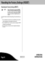
Resetting the Factory Settings (RESET)
NOTE:
Please note that when carrying out a RESET,
all the user settings are deleted. The registra
tion of the sensors is retained! After a RESET
has been executed, the 4-digit Entry Code is
1-2-3-4!
Proceed as follows to reset the factory settings on the wireless alarm sys
tem:
1. Use a screwdriver to loosen the screw in the battery and connection
socket compartment on the underside of the base unit.
2. Press the RESET button. The alarm system acknowledges a RESET
by means of an acoustic signal.
3. Close the battery and connection socket compartment and tighten
the screw.
Page 30
Giu
OPERATING
INSTRUCTIONS
Registering and Deregistering Sensors / System Extesion
Registering Sensors
Deregistering Sensors
Up to 32 sensors can be registered on the wireless alarm system.
1. Enter the device-specific Entry Code. Confirm it by pressing .
If you purchase optionally available sensors, such as additional remote
controls, smoke detectors etc., they must be registered manually.
2. Press the button. Review appears in the display.
Proceed as follows to register the sensors:
1. Enter the device-specific Entry Code. Confirm it by pressing .
2. Press the button to open the menu. Use the and
buttons to select the Register menu option. Confirm it by
pressing .
3. Search… appears in the display.
4. Activate the sensor to be registered. To do this, please refer to the
description supplied with the sensor.
5. Open Sensor01 or SmokeSensor01, for example, appears in the
display. You can rename the sensor, if necessary. Confirm it by
pressing .
6. Voice Record appears in the display. Press to retain the
standard message or press to record an individual message.
7. Confirm it by pressing .
NOTE:
3. Press the buttons and to select the sensor to be
deregistered.
4. Press the button. Delete? appears in the display.
5. Confirm it by pressing . Empty appears in the display.
6. Press the button twice to exit from the menu.
System Extension
You can order accessories and options for the wireless alarm system via
the following web site
If you do not confirm it by pressing the button, recording is automatically ended after
10 seconds.
www.olympia-vertrieb.de
Products
Security Products
8. Your individual message is played back. The main menu reappears
in the display.
Wireless Alarm Systems
OPERATING
INSTRUCTIONS
Giu
Page 31
Changing the Batteries
Remote Control
Changing the Batteries
If the battery charge of the sensors is low or practically empty, one of the
following status messages appear in the display:
Battery capacity low
1. bAtt Lo appears in the display. The sensor in question, e.g. Open
Sensor01 is indicated.
2. If you activate the alarm system, 5 successive, short acoustic signals
are issued.
NOTE:
Change the batteries!
Base Unit
The icon in the display indicates a low battery capacity in the base unit.
Change the batteries!
Battery charge empty
1. bAtt off appears in the display. The sensor affected, e.g. Open Sen
sor01 is indicated.
2. If you activate the alarm system, 5 successive, short acoustic signals
are issued.
NOTE:
Page 32
1. Use a precision screwdriver to loosen the screw in the battery com
partment on the underside of the remote control unit.
2. Remove the cover of the battery compartment.
3. Remove the battery contained.
4. Insert a new CR2430 3 V lithium battery in the battery compartment
(ensure correct polarity).
5. Replace the cover on the battery compartment.
6. Replace and tighten the screw.
Change the batteries! A connection between
the sensor and base unit is no longer guaran
teed!
1. Use a screwdriver to loosen the screw in the battery and connection
socket compartment on the underside of the base unit.
2. Remove the lid from the battery and connection socket compartment.
3. Remove the batteries contained.
4. Insert three new AAA alkaline batteries in the battery compartment
(pay attention to correct polarity).
5. Replace the lid on the battery and connection socket compartment.
6. Replace and tighten the screw.
Giu
OPERATING
INSTRUCTIONS
Regular Maintenance and Servicing
Regular Maintenance and Servicing
Base Unit
1. Disconnect the base unit from the power outlet before cleaning it!
2. Clean the surface of the housing with a soft, lint-free cloth. Never use
any chemicals or scouring agents.
NOTE:
Never immerse the equipment in water!
OPERATING
INSTRUCTIONS
Giu
Page 33
Information on Disposal
Information on Disposal
The implementation of European law in national laws and direct
ives obliges you to dispose of consumable goods appropriately.
This serves to protect both persons and the environment. The
adjacent symbol indicates that electrical and electronic appar
atus and batteries no longer required must be disposed of sep
arate from normal household waste.
Old or unwanted devices must be disposed of at collection
points provided by public waste authorities.
Batteries and power packs must be disposed of at shops
which sell batteries or collection points which provide the corres
ponding containers.
Packaging materials must be disposed of according to local
regulations.
Page 34
Giu
OPERATING
INSTRUCTIONS
Technical Data
Technical Data
Remote Control
The wireless alarm systems in the Protect 9XXX-Series operate within the
frequency band specially reserved for security technology in the 868 MHz
frequency range. This ensures that interference to the wireless alarm sys
tem by other consumer products, such as baby monitors, is ruled out.
However, it cannot be ruled out that the radio transmission suffers intermit
tent or continuous interference due to defective components of other elec
trical or electronic products, such as ventilators and antenna amplifiers. In
addition, radio transmission can be subject to interference from external
sources with wilful intent.
Weight: . . . . . . . . . . . . . . . . . . 24 g
Base Unit
Weight: . . . . . . . . . . . . . . . . . . 228 g (without batteries)
Dimensions (WxHxD): . . . . . (40 x 60 x 14.5) mm
Frequency: . . . . . . . . . . . . . . . 868 MHz
Battery: . . . . . . . . . . . . . . . . . . Lithium CR2430 3 V
Technical Modifications
This operating instruction manual serves purely for information purposes.
Its content is not part of any contract for sale.
All the data relates to nominal values. The equipment and options de
scribed may differ from country to country according to national require
ments.
Dimensions (WxHxD): . . . . . (172 x 105 x 31) mm
Frequency: . . . . . . . . . . . . . . . 868 MHz
Battery: . . . . . . . . . . . . . . . . . . 3 AAA alkaline
Power adapter plug: . . . . . . . 6 VAC, 1 A
Number of sensors: . . . . . . . . Max. 32
OPERATING
INSTRUCTIONS
Giu
Page 35
CE-Mark
CE Mark
The device fulfils the requirements stipulated in the EU Directive:
S
1999/5/EC (R&TTE)
The CE Mark on the device confirms conformity.
Page 36
Giu
OPERATING
INSTRUCTIONS
Empty Page
Empty Page
6HLWH
Empty Page
Entry Code
This is your individual, device-specific Entry Code!
If you want to change this predefined Entry Code, please refer to Chapter "Configuration" in this operating instruction manual.
Keep this operating manual in a safe place away from the wireless alarm system!
Please note that the Copyright of this operating instruction manual is by Olympia and, therefore, must not be further copied, published or sold in any form.
The information contained in the operating instruction manual is only intended for personal use.
All rights reserved.
6HLWH