1
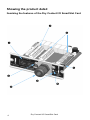
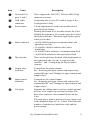
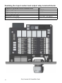
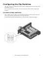
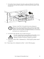
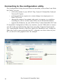
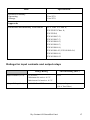
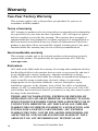
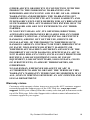
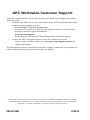
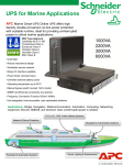
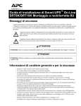
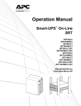
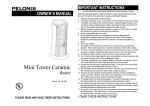
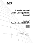
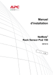
Installation and
Configuration
Dry Contact I/O
SmartSlot Card
AP9613
This manual is available in English on the enclosed CD.
Contents
Safety Overview 1
Important Safety Information . . . . . . . . . . . . . . . . . . . . . . . . . . . . 1
Product Overview 2
Introduction. . . . . . . . . . . . . . . . . . . . . . . . . . . . . . . . . . . . . . . . . . . 2
Product description 2
Hardware and software requirements and tools needed 3
Showing the product detail . . . . . . . . . . . . . . . . . . . . . . . . . . . . . . 4
Itemizing the features of the Dry Contact I/O SmartSlot Card 4
Itemizing the input contact and output relay terminal blocks 6
Configuring the Dip Switches 7
Location of dip switches . . . . . . . . . . . . . . . . . . . . . . . . . . . . . . . . 7
Dip switches: input and outputs . . . . . . . . . . . . . . . . . . . . . . . . . . 8
Installing 9
Planning your installation . . . . . . . . . . . . . . . . . . . . . . . . . . . . . . . 9
Operating considerations 9
Connection strategies 11
Installation steps . . . . . . . . . . . . . . . . . . . . . . . . . . . . . . . . . . . . . 12
Connecting to the configuration utility . . . . . . . . . . . . . . . . . . . 14
Specifications 16
Electrical, physical, environmental, and approval
specifications 16
Ratings for input contacts and output relays 17
Warranty 18
Two-Year Factory Warranty. . . . . . . . . . . . . . . . . . . . . . . . . . . . . 18
Terms of warranty 18
Non-transferable warranty 18
Exclusions 18
Warranty claims 19
Dry Contact I/O SmartSlot Card
i
Disclaimer 20
APC Worldwide Customer Support 32
ii
Dry Contact I/O SmartSlot Card
Safety Overview
Important Safety Information
Follow all applicable electrical codes for your installation area.
Read the instructions carefully to become familiar with the equipment before
trying to install, operate, service or maintain it. The following special messages
may appear throughout this manual or on the equipment to warn of potential
hazards or to call attention to information that clarifies or simplifies a procedure.
The addition of this symbol to a Danger or Warning safety label
indicates that an electrical hazard exists which will result in personal
injury if the instructions are not followed.
This is the safety alert symbol. It is used to alert you to potential
personal injury hazards. Obey all safety messages that follow this
symbol to avoid possible injury or death.
DANGER
DANGER indicates an imminently hazardous situation which, if not avoided, will
result in death or serious injury.
WARNING
WARNING indicates a potentially hazardous situation which, if not avoided, can
result in death or serious injury.
CAUTION
CAUTION indicates a potentially hazardous situation which, if not avoided, can
result in minor or moderate injury.
NOTICE
NOTICE addresses practices not related to physical injury including certain
environmental hazards, potential damage or loss of data.
Dry Contact I/O SmartSlot Card
1
Product Overview
Introduction
The Schneider Electric™ Dry Contact I/O SmartSlot Card (AP9613) is a
management product that provides the following features:
•
UPS status information presented through 6 fully isolated output
relays. This is expandable to 8 using universal input/output ports and
optional Dry Contact I/O Accessory (AP9810)
•
UPS control and testing by using 4 opto-isolated input contacts. An
additional 4 input contacts (non opto-isolated) may be added using
universal input/output ports and an optional Dry Contact I/O Accessory
(AP9810)
•
UPS control and testing based on environmental conditions using
universal input/output ports and an optional Environmental Sensor
(AP9335T or AP9335TH)
•
screw terminal connectors for easy integration into various
management systems
•
a Configuration Utility user interface to customize your setup, see
“Connecting to the configuration utility” on page 14
For more details, see “Showing the product detail” on page 4, “Configuring the
Dip Switches” on page 7, “Installing” on page 9, “Specifications” on page 16.
Product description
The Schneider Electric Dry Contact I/O SmartSlot Card consists of a printed
circuit board assembly. It installs in the SmartSlot of the UPS host device. The
product contents are:
2
•
the Dry Contact I/O SmartSlot Card
•
the USB A to Mini B cable (to access the Configuration Utility, see
“Connecting to the configuration utility” )
•
this printed manual
Dry Contact I/O SmartSlot Card
Hardware and software requirements and tools needed
The Dry Contact I/O SmartSlot Card works with most APC by Schneider
Electric UPS devices with an output rated less than or equal to 160kVA and an
available SmartSlot.
While most devices meet this requirement; verify the compatibility of your
device by locating it on the APC website, www.apc.com, and checking for
compatible accessories.
You need the following tools:
•
#1 Phillips screwdriver for screw terminals
•
#2 Phillips screwdriver for SmartSlot screws
•
a wrench of size 1" or 25.4 mm, or adjustable, to tighten the grommet
For the Configuration Utility, you need: Windows (XP, 2003, 2008, Vista, or 7)
and Internet Explorer browser v7 or higher.
Dry Contact I/O SmartSlot Card
3
Showing the product detail
Itemizing the features of the Dry Contact I/O SmartSlot Card
4
Dry Contact I/O SmartSlot Card
Item
Name
Description
Universal I/O
ports 1 and 2
These support the AP9335T/ TH and AP9810 dry
contact accessories
USB cable
connector
Connecting this to your PC enables usage of the
Configuration Utility.
Reset button
Use an appropriately sized, non-metallic tool to
press the Reset button.
Holding the button for 5 seconds reboots the Card.
Holding the button for 25 seconds resets the Card to
the factory defaults. (The status light flashes green
when you do this).
Status indicator
• SOLID GREEN indicates communications and
operations are fine
• FLASHING GREEN indicates the Card is
initializing
• FLASHING RED indicates a communication fault
• SOLID RED indicates a non-operational fault
Dip switches
These are located near the back of the front panel on
the right-hand side. See the “Location of dip
switches” and “Configuring the Dip Switches”
sections.
Output relay
terminals
Connections for alarm outputs.
See “Itemizing the input contact and output relay
terminal blocks” and “Ratings for input contacts and
output relays” .
Input contact
terminals
Connections for control inputs.
See “Itemizing the input contact and output relay
terminal blocks” and “Ratings for input contacts and
output relays” .
Cord grip
Supports the cabling that is used to control external
devices, or to connect up external switches. The
bare wires connect to the terminal blocks on the
Card.
The cord grip is plastic and can secure a single cord
with a diameter range of 5.8 – 10mm. This limits the
number of conductors (inside the cord) and the
power ratings.
Dry Contact I/O SmartSlot Card
5
Itemizing the input contact and output relay terminal blocks
Number of positions on each terminal block
Tightening torque
Tightening torque max
Wire stripping length
Minimum wire gauge
Maximum wire gauge
6
9
0.35 N.m
0.4 N.m
5 mm
0.14 mm2 (26 AWG)
2.5 mm2 (14 AWG)
Dry Contact I/O SmartSlot Card
Configuring the Dip Switches
The Dry Contact I/O SmartSlot Card requires configuration before testing, final
installation, and use.
See “Location of dip switches” directly below and “Dip switches: input and
outputs” .
Location of dip switches
The “callout” below points to the location of the dip switches on the card, and
shows one possible configuration: ON-OFF-OFF-ON.
See the other possible configurations at “Dip switches: input and outputs”
Dry Contact I/O SmartSlot Card
7
Dip switches: input and outputs
The table below lists the four possible configurations, with their corresponding
inputs and outputs.
Configuration 1
Configuration 2
Configuration 3
Configuration 4*
OFF-OFF-OFF-ON
ON-OFF-OFF-ON
OFF-ON-OFF-ON
ON-ON-OFF-ON
Device Actions
Inputs
1
Turn the UPS on.
2
Turn the UPS off.
3
Start UPS self-test.
4
Shut down the UPS
when on battery
except for self-test or
runtime calibration.
Turn the UPS off
safely.
Put the UPS in
bypass, if bypass is
available on the
UPS.
Shut down the UPS
when on battery
except for self-test or
runtime calibration.
See
Configuration
Utility
Device State
Outputs
1
The UPS is on-battery (e.g., during a power failure, self-test, or
runtime calibration).
2
The UPS has a low battery.
3
The protected load is not receiving power from the UPS or
communication between the UPS and the Relay I/O Card has been
lost.
4
Replace the UPS battery.
5
The UPS is
overloaded.
The UPS is in bypass UPS commanded to
by selection from
turn off gracefully
software, front panel, (echo of Input 2).
or rear panel.
6
Any UPS fault or
self-test failure.
Any UPS fault, selftest failure, or
overload.
UPS commanded to
turn on
(echo of Input 1).
See
Configuration
Utility
Any UPS fault, selftest failure, overload,
or replace battery
* With this setup (the factory default), the Configuration Utility is used automatically.
8
Dry Contact I/O SmartSlot Card
Installing
See “Planning your installation” directly below, “Installation steps” on page 12,
and “Connecting to the configuration utility” on page 14.
Planning your installation
Operating considerations
DANGER
HAZARD OF ELECTRIC SHOCK, EXPLOSION, OR ARC FLASH
Read and understand this manual and the manuals of the UPS before
installing this card.
Installation must be performed by qualified personnel.
The user is responsible for compliance with all international and national
electric code requirements.
Failure to follow these instructions will result in death or serious injury.
Note the following characteristics of the Dry Contact I/O SmartSlot Card when
making decisions regarding system integration:
•
The coils for all output relays are normally energized. The Card will
generate all possible alarms in case of a system fault, such as cable
failure, removal of the Dry Contact I/O SmartSlot Card, severe UPS
battery discharge, or catastrophic hardware failure on the Card.
•
All output relays are isolated from each other and from the UPS system
ground.
•
All input contacts are isolated from the UPS system ground but are
common to each other
•
Control inputs are driven by user-supplied dry contact outputs. The dry
contact closure sensing voltage available on these inputs is nominally 5
VDC at less than 1 mA. All control inputs are referenced to the UPS
system ground.
•
All control inputs must be stable for a minimum of one second to be
considered valid. Longer delays can be set through the Configuration
Utility. Control inputs can be asserted indefinitely.
•
Be careful to assert just a single input to a device. Avoid initiating
simultaneous, conflicting actions, e.g. input #1 (turn the UPS on) and
input #2 (turn the UPS off).
•
Control inputs are acted upon immediately after validation. However,
there are several UPS conditions that can cause an input to be
ineffective, such as self-test or runtime calibration. For confirmation of
Dry Contact I/O SmartSlot Card
9
inputs, we recommend that an output be configured and monitored
appropriately to determine the effectiveness of an input.
•
Do not wire this Dry Contact I/O SmartSlot Card when the power is on.
•
The installation of this Dry Contact I/O SmartSlot Card must follow
applicable building and electrical codes.
•
Do not use this card to control voltage exceeding 30 VAC or VDC.
•
For proper operation, ensure that the UPS is grounded and the Dry
Contact I/O Card is secured with two screws to the UPS.
•
Use only a single cord with the plastic cord grip.
See “Ratings for input contacts and output relays” on page 17 in
“Specifications” .
10
Dry Contact I/O SmartSlot Card
Connection strategies
You can connect the alarm outputs of the Dry Contact I/O SmartSlot Card in
several ways to meet the requirements of your management systems or switched
load. Both normally open (N.O.) and normally closed (N.C.) systems are
accommodated in any combination of AND or OR configurations.
You can combine Dry Contact I/O SmartSlot Card alarm outputs to form
compound outputs, such as “replace battery OR fault” or “on-battery AND low
battery.”
N. O. AND
N. O.
COM
N. O.
COM
N. O. OR
N. O.
N. O.
COM
COM
N. C. AND
N. C.
N. C.
COM
COM
N. C.
COM
N. C.
COM
mph0452a
N. C. OR
Dry Contact I/O SmartSlot Card
11
Installation steps
Warning: After installation, it is strongly recommended that you
fully test your configuration before putting it into a production
environment.
1. Make all connections to the Dry Contact I/O SmartSlot Card to support
your configuration before continuing. See “Itemizing the input contact
and output relay terminal blocks” on page 6 for information on making
the connections.
Electrostatic discharge: The Dry Contact I/O SmartSlot
Card is sensitive to static electricity. Handle the Card by the
end plate only. Do not touch the exposed printed circuit
board.
2. Use a #2 Phillips-head screwdriver to remove the two screws retaining
the slot cover on the host device. Keep the screws for use later. Keep the
slot cover for future use.
12
Dry Contact I/O SmartSlot Card
3. Orient the Card to fit in the Card slot as shown. Slide the Card all the
way into the slot until the end plate is flush with the back panel of the
host device.
Trying to install the Card upside down may damage it.
Observe the correct orientation of the Card. The sides of the
printed circuit board align with the guides in the sides of the
Card slot. The slot may be oriented horizontally or vertically in
the host device, which must be off.
4. Secure the Card with the screws removed in step 3.
In order to provide proper grounding, the SmartSlot screws
must be installed, the metal clamp must be securely
tightened, and the UPS must be properly grounded.
5. Ensure the status LED is illuminated (see “Showing the product detail”
on page 4).
See “Connecting to the configuration utility” on the following page.
Dry Contact I/O SmartSlot Card
13
Connecting to the configuration utility
The Configuration Utility does not need to be installed, it runs off the Card. With
the Utility, you can:
•
review the status of your AP9613 Dry Contact I/O SmartSlot Card and
Universal I/O ports
•
perform actions in response to a status change in an input port or to
some UPS event
•
change the status of an output relay port in response to a condition
occurring in a device such as your UPS or an environmental monitor
•
upgrade the firmware on your AP9613 Dry Contact SmartSlot I/O Card
To launch the Configuration Utility user interface, use the USB cable to connect
your PC to the port indicated by item #2 on your Dry Contact I/O front panel
(see “Itemizing the features of the Dry Contact I/O SmartSlot Card” on page 4).
When the Card is connected to the host PC, it displays as a drive letter on your
PC, see drive E in the graphic below for example.
14
Dry Contact I/O SmartSlot Card
To run the Utility, launch the runme.hta file located in the root of the drive.
For information on using the Configuration Utility user interface, refer to its
online help.
When you connect your Card with your PC using the USB cable, the
Configuration Utility reads a file called config.lua on the Card. Each time
you save a new configuration using the Utility, this file is overwritten. It is also
possible to edit config.lua directly using a text editor like Notepad or
Microsoft Word.
See the section in the Configuration Utility online help called “Copying your
Configuration” for information on copying your configuration to another
installation of the Card by copying the config.lua file.
Dry Contact I/O SmartSlot Card
15
Specifications
For all specifications, when there is a difference between the VDE and
UL approval standards, use the lower rating.
Electrical, physical, environmental, and approval
specifications
Item
Specification
Electrical
Nominal switching capacity
3A@ 30 VAC or VDC
Rated voltage
24 VDC
Rated current
200 mA
Input Contact (#1–4) and
Output Relay (#1–6)
See “Ratings for input contacts and
output relays” on page 17
Physical
Size
(height × width × depth)
38.00 x 121.00 x 108.00 mm
1.50 x 4.75 x 4.25 in
Shipping size
(height × width × depth)
73.00 x 165.00 x 234.95 mm
2.86 x 6.50 x 9.25 in
Weight
0.14 kg
0.30 lb
Shipping weight
0.45 kg
1.00 lb
Environmental
Elevation
Operating
Storage
0 to 3000 m (0 to 10,000 ft)
0 to 15 000 m (0 to 50,000 ft)
Temperature
Operating
Storage
0 to 40°C (32 to 104°F)
-15 to 65°C (5 to 149°F)
16
Dry Contact I/O SmartSlot Card
Item
Specification
Relative Humidity
Operating
Storage
0 to 95%
0 to 95%
Approvals
Emissions and Immunity Verification:
FCC Part 15 Class A,
EN 55022 Class A,
EN 55024,
EN 61000-3-2,
EN 61000-3-3,
EN 61000-4-2,
EN 61000-4-3,
EN 61000-4-4,
EN 61000-4-5, EN 61000-4-6,
EN 61000-4-8,
EN 61000-4-11
Ratings for input contacts and output relays
Voltage Rating
Current Rating (Max.)
Input Contact (#1–4)
0–30 VDC
Minimum for active: 4.5 V
Maximum for inactive: 0.5 V
N/A
Output Relay (#1–6)
0–30 VAC or VDC
3 A per relay
(16 A Total Max)
Dry Contact I/O SmartSlot Card
17
Warranty
Two-Year Factory Warranty
This warranty applies only to the products you purchase for your use in
accordance with this manual.
Terms of warranty
APC warrants its products to be free from defects in materials and workmanship
for a period of two years from the date of purchase. APC will repair or replace
defective products covered by this warranty. This warranty does not apply to
equipment that has been damaged by accident, negligence or misapplication or
has been altered or modified in any way. Repair or replacement of a defective
product or part thereof does not extend the original warranty period. Any parts
furnished under this warranty may be new or factory-remanufactured.
Non-transferable warranty
This warranty extends only to the original purchaser who must have properly
registered the product. The product may be registered at the APC Web site,
www.apc.com.
Exclusions
APC shall not be liable under the warranty if its testing and examination disclose
that the alleged defect in the product does not exist or was caused by end user’s
or any third person’s misuse, negligence, improper installation or testing.
Further, APC shall not be liable under the warranty for unauthorized attempts to
repair or modify wrong or inadequate electrical voltage or connection,
inappropriate on-site operation conditions, corrosive atmosphere, repair,
installation, exposure to the elements, Acts of God, fire, theft, or installation
contrary to APC recommendations or specifications or in any event if the APC
serial number has been altered, defaced, or removed, or any other cause beyond
the range of the intended use.
THERE ARE NO WARRANTIES, EXPRESS OR IMPLIED, BY
OPERATION OF LAW OR OTHERWISE, OF PRODUCTS SOLD,
SERVICED OR FURNISHED UNDER THIS AGREEMENT OR IN
CONNECTION HEREWITH. APC DISCLAIMS ALL IMPLIED
WARRANTIES OF MERCHANTABILITY, SATISFACTION AND
FITNESS FOR A PARTICULAR PURPOSE. APC EXPRESS
WARRANTIES WILL NOT BE ENLARGED, DIMINISHED, OR
AFFECTED BY AND NO OBLIGATION OR LIABILITY WILL
ARISE OUT OF, APC RENDERING OF TECHNICAL OR
18
Dry Contact I/O SmartSlot Card
OTHER ADVICE OR SERVICE IN CONNECTION WITH THE
PRODUCTS. THE FOREGOING WARRANTIES AND
REMEDIES ARE EXCLUSIVE AND IN LIEU OF ALL OTHER
WARRANTIES AND REMEDIES. THE WARRANTIES SET
FORTH ABOVE CONSTITUTE APC’S SOLE LIABILITY AND
PURCHASER’S EXCLUSIVE REMEDY FOR ANY BREACH OF
SUCH WARRANTIES. APC WARRANTIES EXTEND ONLY TO
PURCHASER AND ARE NOT EXTENDED TO ANY THIRD
PARTIES.
IN NO EVENT SHALL APC, ITS OFFICERS, DIRECTORS,
AFFILIATES OR EMPLOYEES BE LIABLE FOR ANY FORM
OF INDIRECT, SPECIAL, CONSEQUENTIAL OR PUNITIVE
DAMAGES, ARISING OUT OF THE USE, SERVICE OR
INSTALLATION, OF THE PRODUCTS, WHETHER SUCH
DAMAGES ARISE IN CONTRACT OR TORT, IRRESPECTIVE
OF FAULT, NEGLIGENCE OR STRICT LIABILITY OR
WHETHER APC HAS BEEN ADVISED IN ADVANCE OF THE
POSSIBILITY OF SUCH DAMAGES. SPECIFICALLY, APC IS
NOT LIABLE FOR ANY COSTS, SUCH AS LOST PROFITS OR
REVENUE, LOSS OF EQUIPMENT, LOSS OF USE OF
EQUIPMENT, LOSS OF SOFTWARE, LOSS OF DATA, COSTS
OF SUBSTITUENTS, CLAIMS BY THIRD PARTIES, OR
OTHERWISE.
NO SALESMAN, EMPLOYEE OR AGENT OF APC IS
AUTHORIZED TO ADD TO OR VARY THE TERMS OF THIS
WARRANTY. WARRANTY TERMS MAY BE MODIFIED, IF AT
ALL, ONLY IN WRITING SIGNED BY AN APC OFFICER AND
LEGAL DEPARTMENT.
Warranty claims
Customers with warranty claims issues may access the APC customer support
network through the Support page of the APC Web site, www.apc.com/
support. Select your country from the country selection pull-down menu at the
top of the Web page. Select the Support tab to obtain contact information for
customer support in your region.
Dry Contact I/O SmartSlot Card
19
Disclaimer
The information presented in this manual is not warranted by Schneider Electric
to be authoritative, error free, or complete. Schneider Electric assumes no
liability for damages, violations of codes, improper installation, system failures,
or any other problems that could arise based on the use of this publication.
The information contained in this publication is provided as is. This publication
has been compiled in good faith by Schneider Electric. However, no
representation is made or warranty given, either express or implied, as to the
completeness or accuracy of the information this publication contains.
IN NO EVENT SHALL SCHNEIDER ELECTRIC, OR ANY AFFILIATE
OR SUBSIDIARY COMPANY OF SCHNEIDER ELECTRIC OR THEIR
RESPECTIVE OFFICERS, DIRECTORS, OR EMPLOYEES BE LIABLE
FOR ANY DIRECT, INDIRECT, CONSEQUENTIAL, PUNITIVE,
SPECIAL, OR INCIDENTAL DAMAGES (INCLUDING, WITHOUT
LIMITATION, DAMAGES FOR LOSS OF BUSINESS, CONTRACT,
REVENUE, DATA, INFORMATION, OR BUSINESS INTERRUPTION)
RESULTING FROM, ARISING OUT OF, OR IN CONNECTION WITH
THE USE OF, OR INABILITY TO USE THIS PUBLICATION OR THE
CONTENT, EVEN IF SCHNEIDER ELECTRIC HAS BEEN
EXPRESSLY ADVISED OF THE POSSIBILITY OF SUCH DAMAGES.
SCHNEIDER ELECTRIC RESERVES THE RIGHT TO MAKE
CHANGES OR UPDATES WITH RESPECT TO OR IN THE CONTENT
OF THE PUBLICATION OR THE FORMAT THEREOF AT ANY TIME
WITHOUT NOTICE.
Copyright, intellectual, and all other proprietary rights in the content (including
but not limited to software, audio, video, text, and photographs) rests with
Schneider Electric or its licensors. All rights in the content not expressly granted
herein are reserved. No rights of any kind are licensed or assigned or shall
otherwise pass to persons accessing this information.
This publication shall not be for resale in whole or in part.
Electrical equipment should be installed, operated, serviced, and maintained
only by qualified personnel. A qualified person is one who has skills and
knowledge related to the construction, installation, and operation of electrical
equipment and has received safety training to recognize and avoid the hazards
involved.
20
Dry Contact I/O SmartSlot Card
APC Worldwide Customer Support
Customer support for this or any other product is available at no charge in any of the
following ways:
• Visit the APC Web site to access documents in the APC Knowledge Base and to
submit customer support requests.
– www.apc.com (Corporate Headquarters)
Connect to localized APC Web sites for specific countries, each of which
provides customer support information.
– www.apc.com/support/
Global support searching APC Knowledge Base and using e-support.
• Contact the APC Customer Support Center by telephone or e-mail.
– Local, country-specific centers: go to www.apc.com/support/contact for
contact information.
For information on how to obtain local customer support, contact the representative or
other distributors from whom you purchased your product.
© 2013 APC by Schneider Electric. APC, the APC logo, and TRADE MARK NAMES are owned by
Schneider Electric Industries S.A.S., American Power Conversion Corporation, or their affiliated
companies. All other trademarks are property of their respective owners.
990-0125D
2/2013