1
USER’S MANUAL
STP-103
THERMAL PRINTER
PO
WE
R
ERR
OR
FEE
D
ON
LIN
E
KN04-00003A
Rev. 2.6
www.samsungminiprinters.com
Safety Precautions
In using the present appliance, please keep the following safety
regulations in order to prevent any hazard or material damage.
WARNING
Violating following instructions can cause serious injury or death.
Do not plug several products in one
multi-outlet.
You must use only the supplied adapter.
It is dangerous to use other adapters.
This can provoke over-heating and a fire.
If the plug is wet or dirty, dry or wipe it
before usage.
If the plug does not fit perfectly with the
outlet, do not plug in.
Be sure to use only standardized multioutlets.
WARNING
Violating following instructions can cause slight wound or damage the appliance.
Keep the desiccant out of children’s
reach.
If not, they may eat it.
Install the printer on the stable surface.
If the printer falls down, it can be broken
and you can hurt yourself.
ONLY SUPPLIED ADAPTER
PROHIBITED
PROHIBITED
PRINT.ER
PROHIBITED
Do not pull the cable to unplug.
Keep the plastic bag out of children’s reach.
If not, a child may put the bag on his head.
This can damage the cable, which is the
origin of a fire or a breakdown of the printer.
PROHIBITED
Use only approved accessories and do
not try to disassemble, repair or remodel
it for yourself.
Do not use the printer when it is out of
order. This can cause a fire or an
electrocution.
Call your dealer when you need these
services.
Switch off and unplug the printer before
calling your dealer.
PROHIBITED
DISASSEMBLING
PROHIBITED
Do not plug in or unplug with your hands
wet.
You can be electrocuted.
PROHIBITED
PRINER
TO UNPLUG
PRINTER
DEALER
If you observe a strange smoke, odor or
noise from the printer, unplug it before
taking following measures.
Switch off the printer and unplug the set from
the mains.
After the disappearance of the smoke, call
your dealer to repair it.
Do not let water or other foreign objects
in the printer.
If this happened, switch off and unplug the
printer before calling your dealer.
Do not bend the cable by force or leave it
under any heavy object.
A damaged cable can cause a fire.
PROHIBITED
TO UNPLUG
2
PRINTER
PROHIBITED
PRINTER
3
Warning – U.S
Introduction
This equipment has been tasted and found to comply with the limits for a Class A
digital device, pursuant to Part 15 of the FCC Rules. These limits are designed to
provide reasonable protection against harmful interference when the equipment is
operated in a commercial environment. This equipment generates, uses, and can
radiate radio frequency energy and, if not installed and uses in accordance with the
instruction manual, may cause harmful interference to radio communications.
Operation of this equipment in a residential area is likely to cause harmful
interference in which case the user will be required to correct the interference at his
own expense.
The STP-103 and STP-103P Roll Printer are designed for use with electronic
instruments such as system ECR, POS, banking equipment peripheral equipment,
etc.
This equipment has been tasted and found to comply with the limits for a Class B
digital device, pursuant to Part 15 of the FCC Rules. These limits are designed to
provide reasonable protection against harmful interference in a residential
installation. This equipment generates, uses and can radiate radio frequency energy
and, if not installed and used in accordance with the instructions, may cause
harmful interference to radio communications. However, there is no guarantee that
interference will not occur in a particular installation. If this equipment does cause
harmful interference to radio or television reception, which can be determined by
turning the equipment off and on, the user is encouraged to try to correct the
interference by one or more of the following measures:
The main features of the printer are as follows:
1. High speed printing.
2. Low noise thermal printing.
3. RS-232 serial interface (STP-103S), Parallel interface (STP-103P).
4. The data buffer allows the unit to receive print data even during printing.
5. Different print densities can be selected by DIP switches.
Please be sure to read the instruction in this manual carefully before using your new
STP-103S and STP-103P.
NOTE
The socket-outlet shall be near the equipment and it shall be easy accessible.
- Reorient or relocate the receiving antenna.
- Increase the separation between the equipment and receiver.
- Connect the equipment into an outlet on a circuit different from that to which
the receiver is connected.
- Consult the dealer or an experienced radio/TV technician for help.
Notice - Canada
This Apparatus complies with class "A" limits for radio interference as specified in
the Canadian department of communications radio interference regulations.
4
5
Table of Contents
Chapter 1. Unpacking
1-1. Checking the contents of the Printer
Chapter 1. Unpacking ...........................................................7
1-1. Checking the contents of the Printer ........................................................7
1-2. Locating the Printer ..................................................................................7
1-3. Printer Part names ...................................................................................8
1-4. Operating Control Panel ...........................................................................9
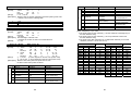
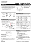
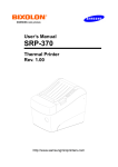
The items illustrated below are included with your printer.
If any items are damaged or missing, please contact your dealer for assistance.
Unpacking
Chapter 2. Connecting the cable ........................................10
Roll paper
2-1. Connecting the AC adapter to your printer .............................................10
2-2. Connecting the Printer to your computer ...............................................11
Power cord
Chapter 3. Installing the Paper Roll ...................................13
Chapter 4. Setting the DIP Switching ................................14
Printer
Adaptor
Chapter 5. Running the Self Test .......................................16
Chapter 6. Hexadecimal Dumping .....................................17
Chapter 7. Code Table ........................................................18
Chapter 8. Functions ..........................................................27
Chapter 9. Control Commands ..........................................29
Cable
1-2. Locating the Printer
Avoid location in direct sunlight or excessive heat.
Avoid or storing the printer in the place subject to excessive moisture.
Do not use or store, horizontal surface for the printer. Avoid places subject to
intense vibration or shock.
Make sure that there is enough space around the printer so that it can be used
easily.
APPENDIX A - Connectors ..........................................................................51
- Serial Type (STP-103S) ........................................................51
- Parallel Type (STP-103P) ......................................................51
APPENDIX B - Specification .........................................................................52
※Option : STP-103DK ........................................................53
6
7
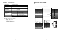
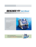
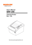
1-3. Printer Part Names
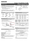
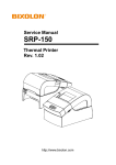
1-4. Operating Control Panel
The control panel has two buttons and two lights.
(1) Cover top
(2) Case top
(3) Case bottom
(4) Control panel
(5) Roller
(6) Power switch
(7) Interface connector (male)
(8) DC Jack
(9) Interface connector (female)
(10) Roll paper
(11) Detector switch
(10)
(5)
(1)
POWER ERROR
FEED
ON LINE
Rear View
(11)
Buttons
The control panel buttons perform paper feeding and on line function.
ON LINE
Press the ON LINE button to ready to receive data from the computer.
FEED
Press the FEED button once to advance paper one line. You can also press the
FEED button continuously to feed paper continuously.
Feed button is valid when ON LINE button is off.
(2)
(4)
(3)
Indicator Lights
The control panel lights provide information on printer conditions.
Rear View
POWER (green)
The POWER light is on when the printer power is on.
(6)
(7)
(9)
(8)
ERROR (red)
1) The error LED blinks fast when paper is out.
2) The error LED blinks when the Near End Sensor triggered.
STP-103S
STP-103P
Control Panel
POWER ERROR
FEED
ON LINE
8
9
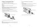
Chapter 2. Connecting the Cable
2-1. Connecting the AC adapter to your printer
When the printer is used, use the optional AC adapter, NH36-240150-I1 for your
printer.
WARNING
Using an incorrect power supply may cause fire or electrical.
2-2. Connecting the printer to your Computer
STP-103S
You need an appropriate serial interface cable to connect your computer to the
printer's built-in interface.
1. Make sure that both the printer and computer are turned off :
then plug the cable connector securely into the printer's interface connector.
2. Tighten the screws on both sides of the cable connector.
CAUTION
When connecting or disconnecting the power supply from the printer, make sure
that the power supply is not plugged into an electrical outlet ; otherwise you may
damage the power supply or the printer
1. Make sure that the printer's power switch is turned off, and that the power
supply's power cord is unplugged from the electrical outlet.
25 Pin Female Type
2. Check the label on the power supply to make sure that the required voltage
matches that of your electrical outlet.
3. Plug the power supply's DC cable connector into the printer's power connector as
shown below.
STP-103S / STP-103P
3. Plug the other end of the cable into the computer.
4. Plug the AC adapter's power cord into an electrical outlet.
NOTE
To remove the DC cable connector grasp the connector at the arrow and pull it
straight out. Make sure that the main unit's power cord is unplugged before you
disconnect the DC cable connector.
10
11
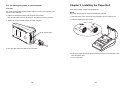
2-2. Connecting the printer to your Computer
STP-103P
Chapter 3. Installing the Paper Roll
Use a paper roll that matches the specifications.
You need an appropriate parallel interface cable to connect your computer to the
printer's built-in interface.
1. Make sure that both the printer and computer are turned off :
then plug the cable connector securely into the printer's interface connector.
2. Tighten the screws on both sides of the cable connector.
NOTE
The printer must be turned off before installing the paper roll.
1. Open the printer cover and remove the used paper roll core if there is one.
2. Insert the paper roll as shown below.
25 Pin Female Type
3. Plug the other end of the cable into the computer.
3. Pull out the paper roll until the paper comes out from the top of the printer. Then
close the printer cover.
4. Turn on the Printer.
12
13
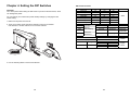
Chapter 4. Setting the DIP Switches
CAUTION
Turn off the printer while setting the DIP switch to prevent an electrical short, which
can damage the printer.
You can change your interface and printer density settings by changing the DIP
switch setting.
1. Make sure the printer is turned off.
2. There are a switch. Notice that ON is marked on each set of switches.
Use tweezers or another narrow tool to move the switches.
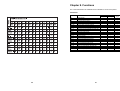
DIP Switch Functions
BPS
2400 bps
4800 bps
9600 bps
19200 bps
38400 bps
57600 bps
115200 bps
SW1
On
Off
Off
On
On
Off
On
SW
SW4
SW5
Function
Density
Handshaking
SW8
Firmware
Download
SW2
Off
On
Off
Off
On
On
On
English
Off
Korean
9600
Off
Normal
RTS/CTS
Default
Normal
RTS/CTS
(DTR/DSR)
Download
Printing
Printing
SW6
CPL
On
Off
On
Off
1
3. Use the following tables to set the DIP switches.
14
Default
On
Dark
Xon/Xoff
SW7
Language
On
SW3
Off
Off
On
On
Off
On
On
15
Default
24
32
Johap
Wansung
English
32CPL
Chapter 5. Running the Self-test
Chapter 6. Hexadecimal Dumping
1. Self-test printing
This feature allows experienced users to see exactly what data is coming to the
printer. This can be useful in finding software problems. When you turn on the
hexadecimal dump function, the printer prints all commands and data in
hexadecimal format along with a guide section to help you find specific commands.
1) Starting the self test
To start printing the self-test on a paper roll, hold down the PAPER FEED
button and turn on the printer with the cover closed. The self-test prints the
current printer settings, which provide the following information :
To use the hexadecimal dump function, follow these steps:
1. After you make sure that the printer is off. Close the cover.
- control software version
2. Turn on the printer, while holding down the FEED button and ONLINE button.
- dip switch state
3. Then the printer enters the hexadecimal dump mode.
2) Standby state
After printing the current printer status, the printer prints the message
"Please press the FEED BUTTON.". The LED indicator blinks and the
printer enter the test printing standby state.
Press the FEED BUTTON to start test printing.
4. Run any software program that sends data to the printer. The printer will print all
the codes it receives in a two-column format. The first column contains the
hexadecimal codes and the second column gives the ASCII characters that
corresponds to the codes.
1B
1B
41
2. Ending the self-test
After a number of lines are printed, the printer indicates the end of the
self-test by printing " ** TEST COMPLETED ** ".
If the self-test is not completed, then you must reboot your printer.
21
25
42
00
01
43
1B
1B
44
26
63
45
02
34
46
40
00
47
40
1B
48
• A period (.) is printed for each code that has no ASCII equivalent.
• During the hex dumping, any commands other than DEL EOT and DLE ENQ
do not function.
5. When the printing finishes, turn off the printer.
6. Turn on the printer and then the hexadecimal mode is off.
16
.!..&.@@
. % . . c4 . .
ABCDEFGH
17
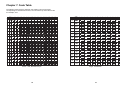
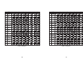
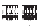
Chapter 7. Code Table
The following pages show the character code tables. To find the character
corresponding to a hexadecimal number, count across the top of the table for the
For example, 4A=J.
#
PC437 : USA, Standard Europe
18
Page1 : KATAKANA
19
PC850 : Multilingual
20
PC860 : Portuguese
21
PC863 : Canadian – French
22
PC865 : Nordic
23
SP
PC858: Euro
24
Space Page
25
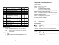
Chapter 8. Functions
The commands listed in the table below are available for control of the printer.
Commands
Command
HT
LF
CR
DLE EOT
DLE ENQ
ESC SP
ESC !
ESC $
ESC %
ESC &
ESC *
ESC ESC 2
ESC 3
ESC =
ESC ?
ESC @
ESC D
ESC E
ESC J
ESC R
ESC V
ESC \
ESC a
26
Name
Horizontal tab
Print and line feed
Print and carriage return
Real-tine status transmission
Real-time request to printer
Set right-side character spacing
Select print mode(s)
Set absolute print position
Select/cancel user-defined character set
Define user-defined characters
Select bit-image mode
Turn underline mode on/off
Select 1/6-inch line spacing
Set line spacing
Select peripheral device
Cancel user-defined characters
Initialize printer
Set horizontal tab positions
Turn emphasized mode on/off
Print and feed paper
Select an international character set
Turn 90 clockwise rotation mode on/off
Set relative print position
Select justification
27
Command Classification
Execution
Setting
○
○
○
○
○
○
○
○
○
○
○
○
○
○
○
○
○
○
○
○
○
○
○
○
Standard
Mode
○
○
○
○
○
○
○
○
○
○
○
○
○
○
○
○
○
○
○
○
○
○
○
○
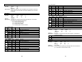
Chapter 9. Control Commands
Command Notation
Command
Esc c 5
Esc d
Esc t
Esc {
FS p
FS q
GS !
GS *
GS /
GS :
GS B
GS H
GS I
GS L
GS P
GS W
GS ^
GS a
GS b
GS f
GS h
GS k
GS v
GS w
Name
Enable/disable panel FEED buttons
Print and feed paper n lines
Select character code table
Turn upside-down printing mode on/off
Print non-volatile bit image
Define non-volatile bit image
Select character size
Define downloaded bit image
Print downloaded bit image
Start/end macro definition
Turn white/black reverse printing mode
on/off
Select printing position of HRI characters
Transmit print ID
Set let margin
Set vertical and horizontal motion unite
Set printing area width
Execute macro
Enable/disable Automatic Status Back
Turn smoothing mode on/off
Select font for HRI characters
Set bar code height
Print bar code
Print raster bit image
Set bar code width
Command Classification
Execution
Setting
0
0
0
0
0
0
0
0
0
0
0
Standard
Mode
0
0
0
0
0
0
(0)
•
0
0
0
0
0
(0)
0
(0)
0
0
0
0
0
(
0
0
0
0
0
0
0
0
0
0
0
0
0
0
0
0
Command classification
Executing : Printer executes the command, which does not affect the
following data.
Setting
: Printer uses flags to make setting, and those setting affect
the following data.
Standard mode
○ : Enabled
(○) : Enabled only when the command is used at the beginning of a line.
● : Enabled only when data is not present in the buffer.
X : Disable
28
XXXX Command
[Name]
The name of the command.
[Format]
The code sequence.
ASCII indicates the ASCII equivalents.
Hex indicates hexadecimal equivalents.
Decimal indicates the decimal equivalent.
[ ]k indicates the contents of the [ ] should be repeated k times.
[Range]
Gives the allowable ranges for the parameters.
[Description] Describes the function of the command.
[Notes]
Provides important information on setting and using the printer
command, it necessary.
[Default]
Gives the default values, if any, for the command parameters.
[Reference] Lists related commands.
[Example]
Provides examples using the command.
The numbers followed by H are hexadecimal
The numbers followed by B are binary.
The numbers denoted by ( ) are decimal.
Explanation of Terms
LSB
Least Significant Bit
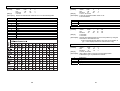
Control Commands
HT
[Name]
[Format]
Horizontal tab
ASCII
HT
Hex
09
Decimal
9
[Description] Moves the print position to the next horizontal tab position.
LF
[Name]
[Format]
Print and line feed
ASCII
LF
Hex
0A
Decimal
10
[Description] Prints the data in the print buffer and feeds one line based on the
current line spacing.
29
CR
[Name]
[Format]
Print and carriage return.
ASCII
HT
Hex
0D
Decimal
13
[Description] When automatic line feed is enabled, this command functions the
same as LF; when automatic line feed is disabled, this command
is ignored.
DLE EOT n
[Name]
[Format]
Real-time status transmission.
ASCII
DLE
EOT
n
HEX
10
04
n
Decimal
16
4
n
[Range]
1≤n≤4
[Description] Transmits the selected printer status specified by n in real time,
according to the following parameters:
n=1 : Transmit printer status.
n=2 : Transmit off-line status.
n=3 : Transmit error status.
n=4 : transmit paper roll sensor status.
n=1 : printers status.
Bit
Off/On
Hex
0
Off
00
1
On
02
2
Off
00
3
Off
00
On
08
4
On
10
5-6
7
Off
00
Decimal
0
2
0
0
8
16
0
Function
Not used. Fixed to Off
Not used. Fixed to On
Not used.
On-line
Off-line
Not used. Fixed to On
Undefined
Not used. Fixed to Off
n=2 : Off-line status
Bit
Off/On
Hex
0
Off
00
1
On
02
2
Off
00
On
04
3
Off
00
On
08
4
On
10
5
Off
00
6
Off
00
7
Off
00
Decimal
0
2
0
4
0
8
16
0
0
0
Function
Not used. Fixed to off.
Not used. Fixed to on.
Cover is closed.
Cover is open.
Paper is not being fed by using the PAPER FEED button.
Paper is being fed by the PAPER FEED button.
Not used. Fixed to on.
Not used. Fixed to off.
Not used. Fixed to off.
Not used. Fixed to off.
30
n=3 : Error status
Bit
Off/On
0
Off
1
On
2
3
Off
4
On
5
Off
6
Off
7
Off
Hex
00
02
00
10
00
00
00
decimal
0
2
0
16
0
0
0
Function
Not used. Fixed to Off.
Not used. Fixed to On.
Undefined.
Not used. Fixed to Off.
Not used. Fixed to On.
Not used. Fixed to Off.
Not used. Fixed to Off.
Not used. Fixed to Off.
n=4 : Continuous paper sensor status
Bit
Off/On
Hex Decimal Function
0
Off
00
0
Not used. Fixed to Off.
1
On
02
2
Not used. Fixed to On.
2,3 Off,Off
00
0
Paper roll near-end sensor is Off.
On,On
0C
12
Paper roll near-end sensor is On.
4
On
10
16
Not used. Fixed to On.
5,6
Off
00
0
Paper roll sensor. Paper present.
On
60
96
Paper roll end detected by paper roll sensor
7
Off
00
0
Not used. Fixed to Off.
DLE ENQ n
[Name]
[Format]
Real time request to printer
ASCII
DLE
ENQ
n
HEX
10
05
n
DECIMAL
16
5
n
[Range]
1≤ n ≤2
[Description] Respond to a request from the host computer. n specifies the
requests as follows
n
Request
1
Recover from an error and restart printing from the line where the error occurred
2
Recover from an error after clearing the receive and print buffers
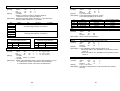
ESC SP n
[Name]
[Format]
Set right-side character spacing
ASCII
ESC
SP
n
Hex
1B
20
n
Decimal
27
32
n
[Range]
0 ≤ n ≤ 255
[Description] Sets the character spacing for the right side of the character to
[n × horizontal or vertical motion units].
31
ESC ! n
[Name]
[Format]
Select print mode(s)
ASCII
ESC
!
n
Hex
1B
21
n
Decimal
27
33
n
[Range]
0 ≤ n ≤ 255
[Description] Selects print mode(s) using n as following table in next page.
Bit
0
1
2
3
4
5
6
7
Off/On
Off
On
Off
On
Off
On
Off
On
Off
On
Off
On
Hex
00
01
00
02
00
08
00
10
00
20
00
80
Decimal
0
1
0
2
0
8
0
16
0
32
0
128
Function
24 character (font A : 12 ×24)
42 character (font B : 9 ×24)
Undefined
32 character (font A : 12 ×24)
Undefined
Emphasized mode not selected.
Emphasized mode selected.
Double-height mode not selected.
Double-height mode selected.
Double-width mode not selected.
Double-width mode selected.
Undefined.
Underline mode not selected.
Underline mode selected.
ESC $ nL nH
[Name]
Set absolute print position
[Format]
ASCII
ESC
$
nL
nH
Hex
1B
24
nL
nH
Decimal
27
36
nL
nH
[Range]
0 ≤ nL ≤ 255
0 ≤ nH ≤ 255
[Description] Sets the distance from the beginning of the line to the position at
which subsequent characters are to be printed.
The distance from the beginning of the line to the print position
is [(nL + nH ×256)×(vertical or horizontal motion unit)] inches.
ESC % n
[Name]
Select/cancel user-defined character set
ASCII
ESC
%
n
Hex
1B
25
n
Decimal
27
37
n
[Range]
0 ≤ n ≤ 255
[Description] Selects or cancels the user-defined character set.
When the Least Significant Bit(LSB) of n is 0, the user-defined
Character set is canceled.
When the LSB of n is 1, the user-defined character set is selected.
32
ESC & y c1 c2 [x1 d1… d(y X x1)]…[xk d1…d(y X xk)]
[Name]
Define user-defined characters
ASCII ESC & y c1 c2 [x1 d1… d(y X x1)]…[xk d1…d(y X xk)]
Hex
1B 26 y c1 c2 [x1 d1… d(y X x1)]…[xk d1…d(y X xk)]
Decimal 27 38 y c1 c2 [x1 d1… d(y X x1)]…[xk d1…d(y X xk)]
[Range]
y=3
32 ≤ c1 ≤ c2 ≤ 126
0 ≤ x ≤ 12 (Font A (12×24))
0 ≤ x ≤ 9 (Font B ( 9×24))
0 ≤ d1… d(y × xk) ≤ 255
[Description] Defines user-defined characters. y specifies the number of bytes in
the vertical direction. C1 specifies the beginning character code for
the definition, and c2 Specifies the final code. x specifies the
beginning character code for the definition, and c2 specifies the final
code.
ESC * m nL nH d1... dk
[Name]
Select bit-image mode
[Format]
ASCII
ESC
*
m
nL nH d1... dk
Hex
1B
2A
m
nL nH d1... dk
Decimal
27
42
m
nL nH d1... dk
[Range]
m = 0, 1, 32, 33
0 ≤ nL ≤ 255 , 0 ≤ nH ≤ 3 , 0 ≤ d ≤ 255
[Description] Selects a bit-image mode using m for the number of dots specified
by nL and nH, as follows:
m
Mode
0
1
32
33
8-dot single-density
8-dot double-density
24-dot single-density
24-dot double-density
Vertical Direction
Number
Dots
of Dots Density
8
67 DPI
8
67 DPI
24
200 DPI
24
200 DPI
ESC - n
[Name]
Horizontal Direction(*1)
Dots
Number of Data (k)
Density
100 DPI
nL + nH × 256
200 DPI
nL + nH × 256
100 DPI (nL + nH × 256) × 3
200 DPI (nL + nH × 256) × 3
Turn underline mode on/off
ASCII
ESC
n
Hex
1B
2D
n
Decimal
27
45
n
[Range]
0 ≤n ≤2, 48 ≤n ≤50
[Description] Turns underline mode on or off, based on the following values of n:
n
0,48
1,49
2,50
Function
Turns off underline mode
Turns off underline mode(1-dot thick)
Turns off underline mode(2-dot thick)
33
ESC 2
[Name]
[Format]
ESC @
[Name]
[Format]
Select 1/6-inch line spacing
ASCII
ESC
2
Hex
1B
32
Decimal
27
50
[Description] Selects 1/6-inch line spacing.
Initialize printer
ASCII
ESC
@
Hex
1B
40
Decimal
27
64
[Description] Clears the data in the print buffer and resets the printer mode to
the mode that was in effect when the power was turned on.
ESC 3 n
[Name]
[Format]
Set line spacing
ASCII
ESC
3
n
Hex
1B
33
n
Decimal
27
51
n
[Range]
Sets the line spacing to [n X (vertical or horizontal motion unit)]
inches.
[Description] 0 ≤ n ≤ 255
ESC = n
[Name]
[Format]
Select peripheral device
ASCII
ESC
=
n
Hex
1B
3D
n
Decimal
27
61
n
[Range]
0 ≤ n ≤ 255
[Description] Selects the device to which the host computer sends data, using n
as follows:
Bit
0
1
2
3
4
5
6
7
Off/On
Off
On
-
Hex
00
01
-
Decimal
0
1
-
Function
Printer disabled.
Printer enabled.
Undefined.
Undefined.
Undefined.
Undefined.
Undefined.
Undefined.
Undefined.
ESC ? n
[Name]
[Format]
ESC D n1...nk NUL
[name]
Set horizontal tab positions
[Format]
ASCII
ESC
D
n1...nk
NUL
Hex
1B
44
n1...nk
00
Decimal
27
68
n1...nk
0
[Range]
1 ≤n ≤255
0 ≤k ≤32
[Description] Sets horizontal tab positions.
● n specifies the column number for setting a horizontal tab
position from the beginning of the line.
●k indicates the total number of horizontal tab positions to be set.
ESC E n
[Name]
[Format]
Turn emphasized mode on/off
ASCII
ESC
E
n
Hex
1B
45
n
Decimal
27
69
n
[Range]
0 ≤n ≤255
[Description] Turns emphasized mode on or off.
● When the LSB of n is 0, emphasized mode is turned off.
● When the LSB of n is 1, emphasized mode is turned on.
ESC J n
[Name]
[Format]
Print and feed paper
ASCII
ESC J n
Hex
1B
4A n
Decimal 27
74 n
[Range]
0 ≤n ≤255
[Description] Prints the data in the print buffer and feeds the paper [n X
(vertical or horizontal motion unit)] inches.
Cancel user-defined characters
ASCII
ESC
?
n
Hex
1B
3F
n
Decimal
27
63
n
[Range]
32 ≤n ≤126
[Description] Cancels user-defined characters.
34
35
ESC R n
[Name]
[Format]
Select an international character set
ASCII
ESC
R
n
Hex
1B
52
n
Decimal
27
82
n
[Range]
0 ≤n ≤10
[Description] Selects an international character set n from the following table:
n
0
1
2
3
4
5
6
7
8
9
10
Character set
U.S.A.
France
Germany
U.K
Denmark Ⅰ
Sweden
Italy
Spain
Japan
Norway
Denmark Ⅱ
ESC V n
[Name]
[Format]
Turn 90° clockwise rotation mode on/off
ASCII
ESC
V
n
Hex
1B
56
n
Decimal
27
86
n
[Range]
0 ≤n ≤1, 48 ≤n ≤49
[Description] Turns 90° clockwise rotation mode on off.
N is used follows:
n
0,48
1,49
Function
Turn off 90°clockwise rotation mode
Turns on 90°clockwise rotation mode
ESC 䦢 nL nH
[Name]
Set relative print position
[Format]
ASCII
ESC
䦢
nL
nH
Hex
1B
5C nL
nH
Decimal
27
92
nL
nH
[Range]
0 ≤nL ≤255
0 ≤nL ≤255
[Description] Sets the print starting based on the current position by using the
horizontal or vertical motion unit.
● This command sets the distance from the current position to
[(nL + nH X 256)X(horizontal or vertical motion unit)].
ESC a n
[Name]
[Format]
Select justification
ASCII
ESC
a
n
Hex
1B
61
n
Decimal
27
97
n
[Range]
0 ≤n ≤2, 48 ≤n ≤50
[Description] Aligns all the data in one line to the specified position.
N selects the type of justification as follows:
n
0,48
1,49
2,50
36
Justification
Left justification
Centering
Right justification
37
ESC c 5 n
[Name]
[Format]
ESC { n
[Name]
[Format]
ESC d n
[Name]
[Format]
FS p n m
[Name]
[Format]
Enable/disable panel FEED buttons
ASCII
ESC
c
5
n
Hex
1B
63
35
n
Decimal
27
99
53
n
[Range]
0 ≤n ≤255
[Description] Enables or disables the panel buttons.
● When the LSB of n is 0, the panel FEED buttons are enabled.
● When the LSB of n is 1, the panel FEED buttons are disabled.
Print and feed paper n lines
ASCII
ESC
D
n
Hex
1B
64
n
Decimal
27
100
n
[Range]
0 ≤n ≤255
[Description] Prints the data in the print buffer and feeds the paper n line.
● This command sets the print starting position to the beginning
of the line.
● This command does cot affect the line spacing set by ESC 2 or
ESC 3.
● The maximum paper feed amount is 40 inches. Even if a paper
feed amount of more than 40 inches is set, the printer feeds the
paper only 40 inches.
● When label mode is selected and a paper feed amount that
exceeds the length of one label is set, the printer feeds the
label paper to the next print starting position.
ESC t n
[Name]
[Format]
Select character code table.
ASCII
ESC
t
n
Hex
1B
74
n
Decimal
27
116
n
[Range]
0 ≤n ≤5, n = 11, 255
[Description] Selects a page n from the character code table.
n
0
1
2
3
4
5
11
255
Page
0 : PC437 [U.S.A., standard Europe]
1 : Katakana
2 : PC850 [Multilingual]
3 : PC860 [Portuguese]
4 : PC863 [Canadian-French]
5 : PC865 [Nordic]
11 : PC858 [Euro]
Space page
[Default] n = 0
38
Turns upside-down printing mode on/off
ASCII
ESC
{
n
Hex
1B
7B
n
Decimal
27
123
n
[Range]
0 ≤n ≤255
[Description] Turns upside-down printing mode on or off.
● When the LSB of n is 0, upside-down printing mode is turned off.
● When the LSB of n is 1, upside-down printing mode is turned on.
Print non-volatile bit image
ASCII
FS
p
n
m
Hex
1C
70
n
m
Decimal
28
112
n
m
[Range]
1 ≤ n ≤ 255 , 0 ≤ m ≤3 , 48 ≤ m ≤ 51
[Description] Prints a non-volatile bit image n using the mode specified by m
m
0,48
1,49
2,50
3,51
Mode
Normal
Double-width
Double-height
Quadruple
Vertical dot density
180
180
90
90
Horizontal dot density
180
90
180
90
• n is the number of the non-volatile bit image.
(defined using the FS q command)
• m specifies the bit image mode.
FS q n [xL xH yH d1 …dk]1…[xL xH yL yH d1…dk]n
[Name]
Define non-volatile bit image
[Format]
ASCII
FS q n [xL xH yH d1 …dk]1…[xL xH yL yH d1…dk]n
Hex
1C 71 n [xL xH yH d1 …dk]1…[xL xH yL yH d1…dk]n
Decimal
28 113 n [xL xH yH d1 …dk]1…[xL xH yL yH d1…dk]n
[Range]
1 ≤ n ≤ 255
0 ≤ nL ≤ 255
0 ≤ xH ≤ 3 (when 1 ≤ xL+xH×256≤ 1023)
0 ≤ yL ≤ 1 (when 1≤yL+yH×256≤288)
0 ≤ d ≤ 255
k = (xL+xH×256) × (yL+yH×256)×8
Total defined data area=2M bits(256K bytes)
[Description] Define the non-volatile bit image specified by n
• n specifies the number of the defined non-volatile bit image
• xL, xH specifies(xL + xH×256)×8 dots in the horizontal direction
for the non-volatile bit image you are defining.
• yL, yH specifies (yL + yH×256)x8 dots in the vertical direction for
the non-volatile bit image you are defining.
39
GS ! n
[Name]
[Format]
Select character size
ASCII
GS
!
n
Hex
1D
21
n
Decimal
29
33
n
[Range]
0 ≤n ≤255
Where 1 ≤ Number of times of character height ≤2
1 ≤ Number of times of character width ≤2
[Description] Selects the character height using bits 0 to 1 and selects the
character width using bits 4 to 7, as follows:
Bit
0
1
2
3
4
5
6
7
Off/On
Hex
Decimal
Function
Character height selection. See Table 2.
GS / m
[Name]
[Format]
Print downloaded bit image
ASCII
GS
/
m
Hex
1D
2F
m
Decimal
29
47
m
[Range]
0 ≤m ≤3,48 ≤m ≤51
[Description] Prints downloaded bit image in mode m.
The modes selectable by m as follows:
m
0,48
1,49
2,50
3,51
Mode
Normal
Double-width
Double-height
Quadruple
Vertical Dot Density
200 DPI
200 DPI
100 DPI
100 DPI
Horizontal Dot Density
200 DPI
100 DPI
200 DPI
100 DPI
GS :
[Name]
[Format]
Character width selection. See Table 1
Table 1
Character width Selection
Hex Decimal
Width
00
0
1 (normal)
10
16
2 (double-width)
Table 2
Character height Selection
Hex Decimal
Height
00
0
1 (normal)
01
1
2 (double-height)
GS * x y d1...d (x X y X 8)
[Name]
Define downloaded bit image
[Format]
ASCII
GS
*
x
y
d1...d (x X y X 8)
Hex
1D
2A
x
y
d1...d (x X y X 8)
Decimal
29
42
x
y
d1...d (x X y X 8)
[Range]
1 ≤x ≤255
1 ≤y ≤48
where, x X y ≤1536
0 ≤d ≤255
[Description] Defines a downloaded bit image using the dots specified by x and y.
● x indicates the number of dots in the horizontal direction.
● y indicates the number of dots in the vertical direction.
40
Start or ends macro definition.
ASCII
GS
:
Hex
1D
3A
Decimal
29
58
[Description] Starts or ends macro definition.
GS B n
[Name]
[Format]
Turn white/black reverse printing mode on/off
ASCII
GS
B
n
Hex
1D
42
n
Decimal
29
66
n
[Range]
0 ≤n ≤255
[Description] Turns white/black reverse printing mode on or off.
● When the LSB of n is 0, white/black reverse printing mode is
turned off.
● When the LSB of n is 1, white/black reverse printing mode is
turned on.
GS H n
[Name]
[Format]
Select printing position of HRI characters
ASCII
ESC
H
n
Hex
1D
48
n
Decimal
29
72
n
[Range]
0 ≤n ≤ 3 , 48 ≤n ≤51
[Description] Selects the printing position of HRI characters when printing
bar code.
41
n selects the printing position as follows:
N
0,48
1,49
2,50
3,51
[Default]
GS P x y
[Name]
[Format]
Set horizontal and vertical motion units
ASCII
GS
P
x
y
Hex
1D
50
x
y
Decimal
29
80
x
y
[Range]
0 ≤ x ≤ 255
0 ≤ y ≤ 255
[Description] Sets the horizontal and vertical motion units to 1/x inch, respectively.
When x is set to 0, the default setting value is used.
When y is set to 0, the default setting value is used.
Printing position
Not printed
Above bar code
Below bar code
Both above and below the bar code
● HRI indicates Human Readable interpretation.
n=0
GS I n
[Name]
[Format]
Transmit printer ID
ASCII
ESC
I
n
Hex
1D
49
n
Decimal
29
73
n
[Range]
1 ≤n ≤3 , 49 ≤n ≤51
[Description] Transmits the printer ID specified by n as follows:
n
1,49
2,50
3,51
Printer ID
Printer model ID
Type ID
ROM version ID
Specification
STP-103S / STP-103P
Depends on ROM version
ID(hexadecimal)
30
02
10
GS W nL nH
[Name]
Set printing area width
[Format]
ASCII
GS
W
nL
nH
Hex
1D
57
nL
nH
Decimal
29
87
nL
nH
[Range]
0 ≤nL ≤255
0 ≤nH ≤255
[Description] Sets the printing area width to the area specified by nL and nH.
● The printing area width is set to [(nL + 256 X nH) X horizontal
motion unit] inches.
Printable area
GS L nL nH
[Name]
[Format]
Set left margin
ASCII
GS
L
nL
nH
Hex
1D
4C
nL
nH
Decimal
29
76 nL
nH
[Range]
0 ≤ nL ≤255
0 ≤ nH ≤255
[Description] Sets the left margin using nL and nH.
● The left margin is set to [(nL + nH X 256) X (horizontal motion
unit6)] inches.
Printable area
Left Margin
Printing area width
42
Left Margin
Printing area width
GS ^ r t m
[Name]
[Format]
Execute macro
ASCII
GS
^
r
t
m
Hex
1D
5E
r
t
m
Decimal
29
94
r
t
m
[Range]
0 ≤ r ≤ 255
0 ≤ t ≤ 255
0≤m≤1
[Description] Executes a macro.
● r specifies the number of times to execute the macro.
● t specifies the waiting time for executing the macro.
The waiting time is t X 100 msec for every macro execution.
● m specifies macro executing mode.
● When the LSB of m = 0:
The macro executes r times continuously at the interval
specified by t.
43
● When the LSB of m = 1:
After waiting for the period specified by t, the LED indicator
blinks and the printer waits for the PAPER FEED button to be
pressed. After the button is pressed, the printer executes the
macro once, The printer repeats the operation r times.
GS a n
[Name]
[Format]
Enabled/disable Automatic Status Back(ASB)
ASCII
GS
a
n
Hex
1D
61
n
Decimal
29
97
n
[Range]
0 ( n ( 255
[Description] Enables or disables ASB and specifies the status items to include,
using n as follows:
Bit
0
1
2
3
4~7
Off/On
Off
Off
On
Off
On
Off
On
-
Hex
00
00
02
00
04
00
08
-
Decimal
0
0
2
0
4
0
8
-
First byte (printer information)
Bit
Off/On
Hex Decimal
0
Off
00
0
1
Off
00
0
2
Off
00
0
3
Off
00
0
On
08
8
4
On
10
16
5
Off
00
0
On
20
32
6
Off
00
0
7
On
40
64
Off
00
0
Status for ASB
Not used.
On-line/off-line status disabled
On-line/off-line status enabled
Error status disabled
Error status enabled
Paper roll sensor status disabled
Paper roll sensor status enabled
Undefined
Status for ASB
Not used. Fixed to off
Not used. Fixed to off
Not used.
On-line
Off-line
Not used. Fixed to on
Cover is closed
Cover is open
Paper is not being fed by using the paper
feed button
Paper is being fed by using the paper feed
button
Not used. Fixed to off
44
Second byte (printer information)
Bit
Off/On
Hex Decimal
0
1
2
3
Off
00
0
4
Off
00
0
5
Off
00
0
6
Off
00
0
7
Off
00
0
Status for ASB
Undefined
Undefined
Undefined
Not used. Fixed to off
Not used. Fixed to off
Not used. Fixed to off
Not used. Fixed to off
Not used. Fixed to off
Third bytes (paper sensor information
Bit
Off/On
Hex Decimal Status for ASB
0,1
Off, Off
00
0
Paper roll near-end sensor: paper
adequate
On, On
03
3
Paper roll near-end sensor: paper near end
2,3
Off, Off
00
0
Paper roll end sensor: paper present
On, On
0C
12
Paper roll end sensor: paper not present
4
Off
00
0
Not used. Fixed to off
5,6
Undefined
7
Off
00
0
Not used. Fixed to off
Fourth byte (paper sensor information)
Bit
Off/on
Hex Decimal Status for ASB
0~3
Undefined
4
off
00
0
Not used. Fixed to off
5,6
Undefined
7
Off
00
0
Not used. Fixed to off
[Default]
n=0
GS b n
[Name]
[Format]
Turns smoothing mode on/off
ASCII
GS
b
n
Hex
1D
62
n
Decimal
29
98
n
[Range]
0 ≤ n ≤255
[Description] Turns smoothing mode on or off.
● When the LSB of n is 0, smoothing mode is turned off.
● When the LSB of n is 1, smoothing mode is turned on.
45
GS f n
[Name]
[Format]
Select font for Human Readable interpretation (HRI) characters.
ASCII
GS
f
n
Hex
1D
66
n
Decimal
29
102
n
[Range]
n = 0, 1, 48, 49
[Description] Selects a font for the HRI characters used when printing a bar code.
n selects a font from the following table:
n
0,48
1,49
Font
Font A (12 * 24)
Font B (9 * 24)
GS h n
[Name]
[Format]
Set bar code height
ASCII
GS
h
n
Hex
1D
68
n
Decimal
29
104
n
[Range]
1 ≤n ≤255
[Description] Sets the height of the bar code.
n specifies the number of dots in the vertical direction.
[Default]
n = 162
① GS k m d1...dk NUL ② GS k m n d1...dn
[Name]
Print bar code
[Format]
① ASCII
GS
k
m
d1...dk
NUL
Hex
1D
6B
m
d1...dk
00
Decimal
29
107
m
d1...dk
0
② ASCII
GS
k
m
n
d1...dn
Hex
1D
6B
m
n
d1...dn
Decimal
29
107
m
n
d1...dn
[Range]
① 0 ≤m ≤6
(k and d depends on the bar code system used)
② 65 ≤m ≤73 (n and d depends on the bar code system used)
[Description] Selects a bar code system and prints the bar code.
M selects a bar bode system as follows:
0
1
2
3
Bar Code System
UPC-A
Number of Characters
11≤k≤12
Remarks
48≤d≤57
JAN 13(EAN)
JAN8(EAN)
12≤k≤13
7≤k≤8
4
CODE39
1≤k
5
ITF
1≤k (even number)
6
CODABAR
1≤k
48≤d≤57
48≤d≤57
48≤d≤57,65≤d≤90,32,
36,37,43,45,46,47
48≤d≤57
48≤d≤57,65≤d1≤68,
36,43,45,46,47,58
m
①
46
65
66
67
68
Bar Code System
UPC-A
Number of Characters
11≤n≤12
Remarks
48≤d≤57
JAN13(EAN)
JAN8(EAN)
12≤n≤13
7≤n≤8
69
CODE39
1≤n≤255
48≤d≤57
48≤d≤57
48≤d≤57,65≤d≤90,32,
36,37,43,45,46,47
70
ITF
1≤n≤255
(even number)
71
CODABAR
1≤n≤255
72
73
CODE93
CODE128
1≤n≤255
2≤n≤255
m
②
48≤d≤57
48≤d≤57,65≤d1≤68
36,43,45,47,58
0≤d≤127
0≤d≤127
[When CODE93 (m=72) is used :]
● The printer prints an HRI character (□) as start character at the beginning of
the HRI character string.
● The printer prints an HRI character (□) as a stop character at the end of
the HRI character string.
● The printer prints HRI characters (■ + an alphabetic character) as a control
character (<00>H to <1F>H and <7F>H) :
Control character
ASCII Hex Decimal
NUL
00
0
SOH
01
1
STX
02
2
ETX
03
3
EOT
04
4
ENQ
05
5
ACK
06
6
BEL
07
7
BS
08
8
HT
09
9
LF
0A
10
VT
0B
11
FF
0C
12
CR
0D
13
SO
0E
14
SI
0F
15
HRI
character
■U
■A
■B
■C
■D
■E
■F
■G
■H
■I
■J
■K
■L
■M
■N
■O
Control character
ASCII Hex Decimal
DLE
10
16
DC1
11
17
DC2
12
18
DC3
13
19
DC4
14
20
NAK
15
21
SYN
16
22
ETB
17
23
CAN
18
24
EM
19
25
SUB
1A
26
ESC
1B
27
FS
1C
28
GS
1D
29
RS
1E
30
US
1F
31
DEL
7F
127
47
HRI
character
■P
■Q
■R
■S
■T
■U
■V
■W
■X
■Y
■Z
■A
■B
■C
■D
■E
■T
<Example>
Printing GS k 72 7 67 111
100
101 13 57 51
② Special characters are defined by combining two characters “{“ and one
character. The ASCII character “{“ is defined by transmitting “{“ twice
consecutively.
Specific character
[When CODE128 (m=73) is used :]
● Refer to Appendix J for the information of the CODE128 bar code and
its code table.
● When using the CODE128 in this printer, take the following points into account
for data transmission :
① The top of the bar code data string must be code set selection character
(any of CODE A, CODE B OR CODE C) which selects the first code set.
※ Description of the CODE128 Bar Code
In CODE128 bar code system, it is possible to represent 128 ASCII
characters and 2-digit numerals using one bar code character that is
defined by combining one of the 103 bar code characters and 3 code
sets. Each code set is used for representing the following characters :
* Code set A : ASCII characters 00H to 5FH
* Code set B : ASCII characters 20H to 7FH
* Code set C : 2-digit numeral characters using one character
(100 numerals from 00 to 99)
The following special characters are also available in CODE128 :
* SHIFT characters
In code set A, the character just after SHFIT is processed as a
character for code set B. In code set B, the character just after
SHIFT is processed as the character for code set A. SHIFT
characters cannot be used in code set C.
* Code set selection character (CODE A, CODE B, CODE C)
This character switches the following code set to code set A, B, or C.
* Function character (FNC1, FNC2, FNC3, FNC4)
The usage of function characters depends on the application
software. In code set C, only FNC 1 is available.
48
SHIFT
CODE A
CODE B
CODE C
FNC1
FNC2
FNC3
FNC4
“{“
ASCII
{S
{A
{B
{C
{1
{2
{3
{4
{{
Transmit data
Hex
7B,53
7B,41
7B,42
7B,43
7B,31
7B,32
7B,33
7B,34
7B,7B
Decimal
123,83
123,65
123,66
123,67
123,49
123,50
123,51
123,52
123,123
<Example> Example data for printing “No. 123456”
In this example, the printer first prints “No.” using CODE B, then
prints the following numbers using CODE C.
GS k 73 10 123 66 78 111 46 123 67 12 34 56
* If the top of the bar code data is not the code set selection character,
the printer stops command processing and processes the following
data as normal data.
* If combination of “{“ and the following character does not apply any
special character, the printer stops command processing and
processes the following data as normal data.
* The printer does not print HRI characters that correspond to the shift
characters or code set selection characters.
* HRI character for the function character is space.
* HRI characters for the control character
(<00>H to <1F>H and <7F>H) are space.
<Others> Be sure to keep spaces on both right and left sides of a bar code.
(Spaces are different depending on the types of the bar code.)
49
GS v 0 xL xH yL yH dl…dk
[Name]
Print raster bit image
[Format]
ASCII
GS
v
0
m
xL xH
Hex
1D 76 30
m
xL xH
Decimal
29 118 48
m
xL xH
[Range]
0 ≤ m ≤ 3 , 48 ≤ m ≤ 51
0≤ xL ≤ 255 , 0 ≤ xH ≤ 255 , 0 ≤ yL ≤ 255
0 ≤ d ≤ 255
k = (xL+xH×256) × (yL+yH×256) (k=0)
[Description] Selects raster bit-image mode.
The value of m selects the mode, as follows :
m
0,48
1,49
2,50
3,51
Mode
Normal
Double-width
Double-height
Quadruple
Vertical dot density
200dpi
200dpi
100dpi
100dpi
APPENDIX
yL
yL
yL
yH
yH
yH
dl…dk
dl…dk
dl…dk
Horizontal dot density
200dpi
100dpi
200dpi
100dpi
• xL, xH, selects the number of data bits(xL+xH×256)in the
horizontal direction for the bit image.
• yL, yH, selects the number of data bits (yL+yH×256)in the
vertical direction for the bit image.
GS w n
[Name]
[Format]
Set bar code width
ASCII
GS
w
n
Hex
1D
77
n
Decimal
29
119
n
[Range]
2 ≤n ≤6
[Description] Set the horizontal size of the bar code.
n specifies the bar code width as follows:
N
Module width (mm) for
Multi-level Bar Code
2
3
4
5
6
0.282
0.423
0.564
0.706
0.847
Bi-level Bar Code
Thin element width
Thick element width
(mm)
(mm)
0.282
0.706
0.423
1.129
0.564
1.411
0.706
1.834
0.847
2.258
A : CONNECTORS
Serial Interface Connector (STP-103S)
PRINTER
TXD (O)
RXD (I)
CTS (I)
GND
RTS (O)
FGND
25 PINE MALE
20
19
21
22~25
18
----------------------------------------------------------------------------------------------------CONNECT
PRINTER
/STROBE (I/O)
DATA0 (I/O)
DATA1 (I/O)
DATA2 (I/O)
DATA3 (I/O)
DATA4 (I/O)
DATA5 (I/O)
DATA6 (I/O)
DATA7 (I/O)
/ACK (I)
BUSY (I)
PE (I)
SLCT
/ERROR (I)
N.C
GND
FGND
25 PINE MALE
HOST
/STROBE (I/O)
DATA0 (I/O)
DATA1 (I/O)
DATA2 (I/O)
DATA3 (I/O)
DATA4 (I/O)
DATA5 (I/O)
DATA6 (I/O)
DATA7 (I/O)
/ACK (I)
BUSY (I)
PE (I)
SLCT
/ERROR (I)
/INIT (O)
GND
FGND
25 PINE MALE
1
2
3
4
5
6
7
8
9
10
11
12
13
15
16~21
22~25
1
2
3
4
5
6
7
8
9
10
11
12
13
15
16
18~25
n=3
50
HOST
RXD (I)
TXD (O)
RTS (O)
GND
CTS (I)
DTR (O)
DSR (I)
FGND
9 PINE FEMALE
Parallel Interface Connector (STP-103P)
• Multi-level bar codes are as follows:
UPC-A, UPC-E, JAN13, CODE93, CODE128
• Bi-level bar codes are as follows: CODE39, ITF, CODABAR
[Default]
2
3
7
5
8
4
6
51
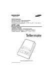
APPENDIX
B : Specification
Printing method
Dot density
Printing width
Paper width
Characters per line
Printing Speed
Receive buffer size
Supply voltage
Environmental
conditions
MCBF
※Option : STP-103DK
Thermal line printing
200 x 200 Dpi (8 dot/mm)
48mm
58mm
32 (Font A) (12x24) , 42 (Font B) (9x24)
Approximately 1.97 inchs / sec
50 mm/sec
at 25℃/printing duty 12.5%
15K bytes
DC
24V 1.5A
0 ~ 40℃ (operating)
Temperature
-10 ~ 50℃ (storage)
30 ~ 80% RH (operating)
Humidity
10 ~ 90% RH (storage)
Mechanical
15,000,000 line
Head
50 million pulse (about 50km)
1) Serial Interface Connector Specification
PRINTER
19
RXD (I)
-----------------------------------
3
TXD (O)
20
TXD (O)
-----------------------------------
2
RXD (I)
18
RTS (O)
-----------------------------------
8
CTS (I)
21
CTS (I)
-----------------------------------
7
RTS (O)
4
DTR (O)
6
DSR (I)
FGND
CONNECT
FGND
22~25
※ Paper
- Paper thickness : 0.06 ~ 0.09mm
- Roll size : Ø60 ~ 57 (w)
- Roll spool diameter
1) Inside : Ø12mm (0.47”)
2) Outside : Ø18mm (0.71”)
HOST
SG
-----------------------------------
SG
9 PINE FEMALE
* RJ11 6P
22
SG
----
1
GND
14
SOL1
----
2
SOL1
16
COMPS/W
----
3
COMPS/W
17
SLCT
----
4
SLCT
5
NC
6
GND
22
SG
----
25 PINE MALE
52
5
53
6
1
2) Parallel Interface Connector Specification
3) Control Command
PRINTER
HOST
1
/STROBE (I/O)
1
/STROBE (I/O)
2
DATA0 (I/O)
2
DATA0 (I/O)
3
DATA1 (I/O)
3
DATA1 (I/O)
4
DATA2 (I/O)
4
DATA2 (I/O)
5
DATA3 (I/O)
5
DATA3 (I/O)
6
DATA4 (I/O)
6
DATA4 (I/O)
7
DATA5 (I/O)
7
DATA5 (I/O)
8
DATA6 (I/O)
8
DATA6 (I/O)
9
DATA7 (I/O)
9
DATA7 (I/O)
10
/ACK (I)
10
/ACK (I)
11
BUSY (I)
11
BUSY (I)
12
PE (I)
12
PE (I)
13
SLCT
13
SLCT
15
/ERROR (I)
15
/ERROR (I)
16
/INIT (O)
22~25
GND
18~25
FGND
GND
FGND
22
SG
----
14
16
SOL1
COMPS/W
-------
2
3
SOL1
COMPS/W
17
SLCT
----
22
SG
----
4
5
6
SLCT
NC
GND
25 PINE MALE
DLE DC4 n m t
[Name]
Generate pulse at real-time.
[Format]
ASCII
DLE
DC4 n
m
t
Hex
10
14
n
m
t
Decimal
16
20
n
m
t
[Range]
n=1, m=0
1≤t≤8
[Description] Outputs the pulse specified by t to connector pin m as follows :
m=0 Connector pin : Drawer kick-out connector pin 2.
The pulse ON time is [t*100ms] and the OFF time is [t*100ms].
[Reference] ESC p
Bell n
[Name]
[Format]
25 PINE MALE
* RJ11 6P
1
GND
ESC p m t1 t2
[Name]
Generate pulse.
[Format]
ASCII
ESC
p
m
t1
t2
Hex
1B
70
m
t1
t2
Decimal
27
112
m
t1
t2
[Range]
m = 0, 48
0 ≤ t1 ≤ 255, 0 ≤ t2 ≤ 255
[Description] Outputs the pulse specified by t1 and t2 to connector pin m
as follows :
m=0 Connector pin : Drawer kick-out connector pin 2.
[Details]
The pulse ON time is [t1*2ms] and the OFF time is [t2*2ms].
If t2 ≤ t1, the OFF time is [t2*2ms].
[Reference] DLE DC4
6
Select bell on time.
ASCII
Bell
t
Hex
07
t (1e t)
Decimal
07
t (30 t)
[Range]
t = 1~30
[Description] The pulse ON time is [t*100ms] and the OFF time is [t*100ms].
1
54
55