1
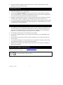
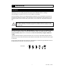
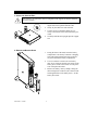
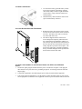
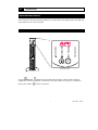
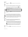
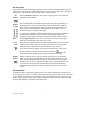
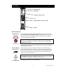
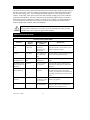
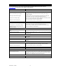
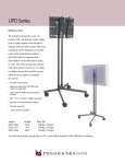
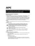
APC Smart-UPS® RT
1000/2000 VA
220/230/240 VAC
Tower/Rack Mount 2U
Uninterruptible Power Supply
User Manual
English
990-1060B 12/2005
1:
SAFETY INFORMATION
American Power Conversion Corporation (APC) is the leading national and international manufacturer of state-of-the-art uninterruptible power supplies, redundant switches, power management software, and related equipment. APC products protect hardware, software, and data from the threat of
power disturbances in business and government offices throughout the world.
The APC Uninterruptible Power Supply (UPS) is designed to prevent blackouts, brownouts, sags,
and surges from reaching your computer and other valuable electronic equipment. The UPS filters
out small utility line fluctuations and isolates your equipment from large disturbances by internally
disconnecting from the utility line. The UPS provides continuous power from its internal battery until
the utility line returns to safe levels.
Changes or modifications to this unit not expressly approved by the party
responsible for compliance could void the warranty.
HANDLING SAFETY
Be careful. Do not lift heavy loads without assistance.
<18 kg (<40 lb)
32–55 kg (70–120 lb)
>55 kg (>120 lb)
18–32 kg (40–70 lb)
This equipment is intended for installation in a temperature-controlled indoor area free of conductive
contaminants. Refer to Specifications at the APC web site for the actual temperature range.
ELECTRICAL SAFETY
•
To reduce the risk of fire, connect only to a circuit provided with a 30 Amp maximum branch
circuit overcurrent protection in accordance with the National Electrical Code ANSI/NFPA or
country specific electrical code.
•
Do not work alone under hazardous conditions.
•
Check that the power cord(s), plug(s), and sockets are in good condition.
•
To reduce the risk of electric shock when grounding, disconnect the equipment from the AC
power outlet before installing or connecting to other equipment. Reconnect the power cord only
after all connections are made.
•
Use one hand, whenever possible, to connect or disconnect signal cables to avoid a possible
shock from touching two surfaces with different electrical grounds.
•
Connect the equipment to a three wire AC outlet (two poles plus ground). The receptacle must
be connected to appropriate branch circuit/mains protection (fuse or circuit breaker). Connection
to any other type of receptacle may result in a shock hazard.
1
990-1060B 12/2005
•
In order to maintain compliance with the EMC directive, output cords attached to the UPS
should not exceed 10 meters in length.
DEENERGIZING SAFETY
•
If the equipment has an internal energy source (battery), the output may be energized when the
unit is not connected to an AC power outlet.
•
To deenergize pluggable equipment: first press the OFF button for more than one second to
switch the equipment off. Disconnect the equipment from the AC power outlet. Unplug the battery connector. Push the ON button to deenergize the capacitors.
Pluggable equipment includes a protective earth conductor that carries the leakage current from
the load devices (computer equipment). Total leakage current must not exceed 3.5 mA.
•
•
Use of this equipment in life support applications where failure of this equipment can reasonably
be expected to cause the failure of the life support equipment or to significantly affect its safety
or effectiveness is not recommended.
BATTERY SAFETY
•
This equipment contains potentially hazardous voltages. Do not attempt to disassemble the unit.
The only exception is for equipment containing batteries. Battery replacement using the procedures below is permissible. Except for the battery, the unit contains no user serviceable parts.
Repairs are to be performed only by factory trained service personnel.
•
Do not dispose of batteries in a fire. The batteries may explode.
•
Do not open or mutilate batteries. They contain an electrolyte that is toxic and harmful to the
skin and eyes.
•
Do not connect the terminals of a battery or battery pack with a wire or other electrically conductive objects.
•
To avoid personal injury due to energy hazard, remove wristwatches and jewelry such as rings
when replacing the batteries. Use tools with insulated handles.
•
Replace batteries with the same number and type of batteries or battery packs as originally installed in the equipment.
BATTERY REPLACEMENT AND RECYCLING
See your dealer or visit the APC web site, www.apc.com/support for information on replacement
battery kits and battery recycling.
Be sure to return the spent battery to APC for recycling. Ship it to APC in the
replacement battery packing material.
990-1060B 12/2005
2
2:
INSTALLATION
UNPACKING
Inspect the UPS upon receipt. APC designed robust packaging for your product. However, accidents
and damage may occur during shipment. Notify the carrier and dealer if there is damage.
The packaging is recyclable; save it for reuse or dispose of it properly.
Check the package contents. The shipping package contains the UPS (with batteries disconnected);
its front bezel (packaged separately); feet (required in tower configuration); and a literature kit containing a software CD, one serial cable, power cord(s), screws for the feet, and product documentation.
The UPS is shipped with the battery disconnected and the front bezel removed. You
will connect the battery and install the plastic bezel (described later) during the installation procedure.
POSITIONING THE UPS
Place the UPS where it will be used. The UPS is heavy. It requires two people for installation due to
its weight. To lighten the UPS, you may remove the battery while you position the UPS. See Removing the Battery Pack, below, for instructions. Select a location sturdy enough to handle the
weight.
You must install the UPS in a protected area that is free of excessive dust and has adequate airflow.
Ensure the air vents on the front and rear of the UPS are not blocked. Allow at least one inch of space
on each side.
m
m
S
S
S
Placement
m
a
a
a
r
r
r
Do not operate the UPS where the temperature and humidity are outside the specified limits. Refer to
the Specifications at the APC web site (www.apc.com).
3
990-1060B 12/2005
INSTALLATION
1. ATTACH THE SUPPORT FEET
If the UPS is to be operated in Tower Configuration the support feet must be attached
for proper stability.
1.
Locate the two feet and the plastic bag containing the four screws packed with the UPS.
2.
Gently lay the UPS on its side as shown.
3.
Use the screws to attach the support feet securely to the bottom of the UPS in the holes provided.
4.
Carefully stand the unit upright upon the support
feet.
1.
Facing the front of the UPS, locate the battery
compartment. The battery connector is hanging
from cables that lead through a hole in the battery door and into the battery compartment.
2.
Use a screwdriver to remove the two battery
door screws located at the left side corners of the
battery door. Set the screws aside in a safe place.
You will replace them later.
3.
Remove the battery door by sliding it along the
cables and past the connector (the connector will
fit through the hole in the battery door). Set the
battery door aside.
2. REMOVE THE BATTERY DOOR
990-1060B 12/2005
4
3. CONNECT THE BATTERY
1.
To connect the battery, push the battery connector into the receptacle in the battery compartment. Press firmly to ensure a tight connection.
You will hear a “snap” when the connector is
seated properly.
2.
Push the battery cables and white cord into the
space with the battery connector.
4. ATTACH BATTERY DOOR AND FRONT BEZEL
1.
Replace the battery door and screw the two battery door screws back into the corners of the battery door. The battery door will cover the battery cables and white cord.
2.
The UPS is shipped with the front bezel removed and packed separately within the main
box. Unpack the bezel and hold it with the cutout section on top. Slide the tab on the bottom of
the bezel into the slot on the bottom of the UPS.
Gently snap the top of the bezel into place. The
bezel can be removed by carefully unsnapping
the top, and then sliding the bezel up and out of
the tab on the bottom of the UPS.
5. CONNECT THE EQUIPMENT TO THE UPS AND CONNECT THE UPS TO THE AC POWER
SUPPLY
1. On the back panel, plug the female end of the power cord into the receptacle. Then plug the
male end into a two-pole, three-wire, grounding receptacle. Avoid using extension cords and
adapter plugs.
2.
Connect the equipment to the UPS using the power cords provided with the equipment.
3.
Turn on all connected equipment. To use the UPS as a master ON/OFF switch, be sure all connected equipment is switched on. The equipment will not be powered until the UPS is turned on.
5
990-1060B 12/2005
6. TURN ON THE UPS
Make sure the battery is connected before turning on the UPS! Press the
button on the front
panel to power up your UPS. This will power up connected equipment if that equipment is turned
on.
The UPS charges its battery when it is connected to utility power. The battery charges
fully during the first twenty four hours of normal operation. Do not expect full run time
during this initial charge period.
The unit performs a self-test automatically when turned on and every two weeks thereafter (by default). Refer to the User Configurable Items section of this manual, below, for details on changing
the default interval.
To turn on the UPS when no utility power is present, see the Cold Start function in the Operations
section of this manual.
7. ACCESSORIES (OPTIONAL)
This UPS is equipped with an accessory slot. See the APC website, www.apc.com, for available accessories.
For additional computer system security, install PowerChute Plus®, Smart-UPS monitoring software. It provides automatic unattended shutdown capabilities on most major network operating systems. PowerChute Plus® and its documentation are included on the CD that is packed with this
UPS.
990-1060B 12/2005
6
3:
OPERATION
INDICATORS AND CONTROLS
The UPS power control and operating indicators are located on the front display panel. The input and
output connectors are on the rear panel.
FRONT PANEL
|
TEST
For Position Only
The ON
and OFF
buttons power the UPS and act as master controls for the connected
equipment if connected equipment is switched on. The UPS remains on as long as it is attached to
utility power and the
switch is not pressed.
7
990-1060B 12/2005
OPERATION
Power
On
Cold
Start
Press and release the
equipment.
button to supply power to the UPS and connected
When the UPS is off and there is no utility power, use the cold start feature to
apply power to the connected equipment from the UPS’s battery. Cold start is
not a normal condition. To cold start the unit, push and hold the
button.
You will hear a short beep then a long beep. During the long beep, release the
button and the unit will cold start.
The charger maintains battery charge when the UPS is plugged in and utility
voltage is present.
Power
Off
Load
Press and release the
equipment.
button to turn off power to the UPS and connected
The five-LED display on the left of the front panel shows the percentage of
available power used by the connected equipment (load). For example, if three
LEDs are lit, the connected load is drawing between 51% and 68% of the UPS
capacity. If all five LEDs are lit, the connected load is drawing between 85% and
100% of capacity. Thoroughly test your entire system to make sure that the UPS
will not become overloaded. In the graphic to the left, the load capacity threshold
is listed next to the LED (these values are not listed on the UPS).
SELF-TEST
The UPS performs a self-test automatically when turned on, and every two
Autoweeks thereafter (by default). Refer to the User Configurable Items table, bematic
low, for details on changing the default interval.
SelfTest
Automatic self-test eases maintenance requirements by eliminating the need for
periodic manual self-tests. During the self-test, the UPS briefly operates the connected equipment on battery. If the UPS passes the self-test, it returns to online
operation. If the UPS fails the self-test, the UPS lights the Replace Battery LED
and immediately returns to online operation. The connected equipment is
not affected by a failed test. To confirm a self-test, failure, recharge the battery
for 24 hours and perform another self-test. If it fails, the battery must be replaced.
Manual
SelfTest
Press and hold the
990-1060B 12/2005
button until the UPS beeps twice to initiate the self-test.
8
UTILITY POWER
During normal operation, the UPS monitors the utility power and delivers power to the connected
equipment. If your system is experiencing excessive periods of high or low voltage, have a certified
electrician check your facility for electrical problems. If the problem continues, contact the utility
company for further assistance.
Online
The online indicator illuminates when the UPS is drawing utility power and performing
double-conversion to supply clean power to the connected equipment.
Utility
Voltage
The UPS has a diagnostic feature that displays the utility voltage. Plug the UPS into the
normal utility power.
266
248
229
210
192
button to view the utility voltage bar graph display. After a few
Press and hold the
seconds the five-LED display on the right of the front panel shows the utility input voltage. Refer to the figure at left for the voltage reading (values are not listed on the UPS).
The UPS starts a self-test as part of this procedure. The self-test does not affect the voltage display.
The display indicates the voltage is between the displayed value on the list and the next
higher value. For example, with three LEDs lit, the input voltage is between 229 and 248
VAC.
If no LEDs are lit and the UPS is plugged into a working AC power outlet, the line voltage is extremely low.
If all five LEDs are lit, the line voltage is extremely high and should be checked by an
electrician.
Bypass
This LED illuminates to indicate the UPS is in Bypass mode. Battery backup is not
available while in this mode. Utility power is being sent directly to connected loads.
The UPS transfers to this mode due to a command received via the computer interface
port or after a UPS internal fault.
Fault
This LED illuminates to indicate the UPS has detected an internal fault. See the Troubleshooting section for details.
9
990-1060B 12/2005
BATTERY POWER
If the utility power fails, the UPS can provide power to the connected equipment from its internal
batteries for a finite period. The UPS sounds an alarm—four beeps every 30 seconds—while operating on battery. The alarm stops when the UPS returns to online operation.
On
Battery
Battery
Charge
When the On Battery indicator is lit the UPS is supplying power to the connected
equipment from its batteries.
The five-LED display on the right of the front panel shows the present charge of
the UPS battery as a percentage of the battery capacity. When all five LEDs are
lit, the battery is fully charged. The LEDs extinguish, from top to bottom, as the
battery capacity diminishes. Refer to the figure at left for the battery capacity
threshold (values are not listed on the UPS).
As a low battery warning, any LEDs illuminated (for the given capacity) flash and
the UPS beeps continuously. The low battery warning default setting can be
changed in terminal mode or through the optional PowerChute software. Refer to
User Configurable Items, below. To see the runtime in minutes for your UPS
model refer to the Runtime Table at the APC website.
Overload
The UPS emits a sustained alarm tone and this LED illuminates when an overload
condition occurs (that is, when the connected equipment exceeds the specified
“maximum load” as defined in the specifications at the APC web site).
The UPS may transfer to Bypass mode during an overload event. If this occurs,
the UPS can then be returned to online mode by pressing the
button. Disconnect nonessential equipment from the UPS to eliminate an overload.
Replace
Battery
Failure of a battery self-test causes the UPS to emit short beeps for one minute
and the Replace Battery LED illuminates. The UPS repeats the alarm every five
hours. The LED flashing indicates the battery is disconnected. The UPS repeats
the alarm every five hours. Check that the battery pack is connected properly. If it
is, perform the self-test procedure after the battery has charged for 24 hours to
confirm the need to replace the battery. The alarm stops if the battery passes the
self-test.
SHUTDOWN MODE
In shutdown mode, the UPS stops supplying power to the connected equipment, waiting for the return of utility power. If there is no utility power present, external devices (such as servers) connected
via the computer interface port or the accessory slot can command the UPS to shut down. This normally is done to preserve battery capacity after the shutdown of protected servers. The UPS scrolls
the front panel indicators sequentially in shutdown mode.
990-1060B 12/2005
10
REAR PANEL
TVSS Ground
Input Plug
Computer Interface Port
Fan
External Battery Connector Port
Outlets
BASIC CONNECTORS
Computer Inter- Power management software and interface kits can be used with the UPS.
Use only interface kits supplied or approved by APC. If used, connect the
face Port
interface cable to the 9-pin computer interface port. Secure the connector
screws to complete the connection.
TVSS Screw
External Battery
Connector Port
Input
Circuit Breaker
Use the APC supplied cable to connect to the Computer Interface Port.
DO NOT use a standard serial interface cable since it is incompatible
with the UPS connector.
The UPS features a transient voltage surge-suppression (TVSS) screw for
connecting the ground lead on surge suppression devices such as telephone
and network line protectors.
External battery packs can be obtained to connect to your UPS and give
longer runtime during power outages. If used, unscrew the protective plate
from in front of the connector port and insert the cable supplied with the battery pack into the connector port. Battery Packs can be daisy chained together to achieve desired run time.
To connect optional external battery pack(s) to the UPS, refer to the SmartUPS RT Battery Pack User’s Manual for instructions. This Smart-UPS RT
XL can support a maximum of ten external battery packs.
If the plunger on the circuit breaker pops out, reduce the load on the UPS by
unplugging equipment and press the plunger in.
11
990-1060B 12/2005
ON BATTERY OPERATION
The UPS switches to battery operation automatically and an internal alarm sounds (periodic beeps) if
the utility power fails. Press the ON button (front panel) to silence the UPS alarm until low battery
(for the current outage only). You can change the audible indicator if you are using PowerChute
software. If the utility power does not return, the UPS continues to supply power to the connected
equipment until exhausted. The UPS will begin to beep continuously approximately two minutes
before final low battery shutdown by default. If you are using a computer, you must manually save
your files and power down before the UPS turns off, unless you are using PowerChute interface
software that provides automatic, unattended shutdown.
UPS battery life differs based on usage and environment. It is recommended that the
battery pack be changed once every three years. See the Run-Time Table for SmartUPS RT on the APC website for approximate run times.
USER CONFIGURABLE ITEMS
NOTE: SETTING THESE ITEMS REQUIRES SOFTWARE, OPTIONAL HARDWARE, OR
CONFIGURATION IN TERMINAL MODE.
FUNCTION
FACTORY
DEFAULT
USER SELECTABLE
CHOICES
DESCRIPTION
Automatic SelfTest
Every 14 days
(336 hours)
Every 7 days
(168 hours),
On Startup Only,
No Self-Test
This function sets the interval at which the
UPS will execute a self-test. Refer to your
software manual for details.
UPS ID
UPS_IDEN
Up to eight characters to define the
UPS
Use this field to uniquely identify the UPS
for network management purposes.
Date of Last Battery Replacement
Manufacture
Date
Date of Battery
Replacement
Reset this date when you replace the battery
pack.
Minimum Capacity
Before Return from
Shutdown
0 percent
15, 25, 35, 50, 60,
75, 90 percent
The UPS will charge its batteries to the
specified percentage before return from a
shutdown.
Duration of Low
Battery Warning
2 minutes
5, 7, 10, 12, 15, 18,
20 minutes
This function sets the time before shutdown
at which the UPS issues a low battery
warning. Set it higher than the default if the
operating system needs more time for shutdown.
Alarm Delay After
Line Fail
5 second delay
30 second delay, At
Low Battery Condition, No Alarm
Set the alarm delay to avoid alarms for
minor power glitches.
Shutdown Delay
20 seconds
0, 60, 120, 240, 480,
720, 960 seconds
This function sets the interval between
when the UPS receives a shutdown command and when shutdown occurs.
990-1060B 12/2005
12
NOTE: SETTING THESE ITEMS REQUIRES SOFTWARE, OPTIONAL HARDWARE, OR
CONFIGURATION IN TERMINAL MODE.
FACTORY
DEFAULT
FUNCTION
USER SELECTABLE
CHOICES
DESCRIPTION
Synchronized
Turn-on Delay
0 seconds
20, 60, 120, 240,
480, 720, 960 seconds
The UPS will wait the specified time after
the return of utility power before turn-on
(for example, to avoid branch circuit overload).
Output Voltage
Setting
230 VAC
240, 220, 225 VAC
Nominal output voltage setting.
High Transfer
Point
+ 10% of output
voltage setting
+5%, +15%, +20%
Maximum voltage that the UPS will pass to
the load during internal bypass operation.
Low Transfer Point
-15% of output
voltage setting
-20%, -25%,
-30%
Minimum voltage that the UPS will pass to
the load during internal bypass operation.
Output Frequency
Automatic
50 ± 3 Hz,
50 ± 0.1 Hz,
60 ± 3 Hz,
60 ± 0.1 Hz
Sets the allowable output frequency of the
UPS. Whenever possible, the output frequency tracks the input frequency. Automatic setting allows 50 +/-3 or 60 +/-3 Hz
depending on the input frequency.
Unit Position
Tower
Rack Mount
The operating configuration of the UPS.
Optional Rail Kit SURTRK is required to
convert to rack mount configuration.
Number of External Battery Packs
0
Number of connected battery
packs.
Defines number of attached external battery
packs for proper runtime prediction. Do
not include the internal pack in this number.
TERMINAL MODE
Terminal mode is a menu driven interface that allows for enhanced configuration of the UPS. This
interface can be accessed using a computer and a common serial communication application, such as
Hyperterminal. To enter and use the Terminal Mode:
1.
Connect a computer to the UPS using the cable supplied with your UPS.
2.
Launch a standard serial communication application, such as Hyperterminal.
3.
Specify the communications port (comm. port) to which you have connected.
4.
Set the following properties: 2400 baud, 8 data bits, no parity, one stop bit, and no flow
control.
5.
Press the enter or return key.
6.
Follow the instructions on the screen to continue in Terminal Mode.
13
990-1060B 12/2005
4:
TRANSPORT, MAINTENANCE, AND TROUBLESHOOTING
TRANSPORTING YOUR UPS
Always DISCONNECT THE BATTERY before shipping in compliance with U.S.
Department of Transportation (DOT) regulations. The battery may remain in the
UPS; it does not have to be removed.
This requirement applies whether the UPS is shipped alone or installed in an
equipment rack or system.
Follow these steps to prepare the UPS for transport.
Due to its weight, removing the UPS from a rack requires two people.
1.
Shut down any equipment attached to the UPS.
2.
Disconnect the UPS from the power supply.
3.
If your unit is in the Tower Configuration, skip this step and continue with Step 4, below. To
remove the unit from a rack, reverse the steps for installation of the UPS into the rack found in
the Rack Mount Installation Sheet found in the Rail Kit.
4.
Remove the front bezel. If you are using the original UPS packaging, you must pack the front
bezel separate from the UPS. Reverse the step for attaching the front bezel found in the Installation section of this manual.
5.
Disconnect the battery. Reverse the steps for connecting the battery found in the Installation
section of this manual.
6.
If your unit is in the Tower Configuration, remove the feet by reversing the directions for attaching the feet found in the Installation section of this manual.
7.
Your UPS can now be placed in its original packaging for transport.
STORAGE
STORAGE CONDITIONS:
Store the UPS in a cool, dry location, with its batteries fully charged. Disconnect any cables connected to the computer interface port to avoid unnecessary battery drainage.
EXTENDED STORAGE:
At -15 to +30 °C (+5 to +86 °F), charge the UPS battery every six months.
At +30 to +45 °C (+86 to +113 °F), charge the UPS battery every three months.
990-1060B 12/2005
14
REPLACING THE BATTERY PACK
This UPS has an easy to replace, hot-swappable battery pack. Replacement is a safe procedure, isolated from electrical hazards. You may leave the UPS and connected equipment on while replacing
the battery. See your dealer or contact APC for information on replacement battery packs. This procedure is used in both Tower and Rack Mount configurations.
Once the battery is disconnected, the loads are not protected from power outages.
REMOVE AND REINSTALL THE BATTERY PACK
Be careful during removal and replacement of the battery pack; it is heavy.
Remove Battery
1.
Remove front bezel and the battery door if
they are attached. (See the instructions in
the Installation section of this manual to
remove the battery door and front bezel.)
2.
If the battery is connected, disconnect the
battery by pulling on the connector firmly.
3.
Grasp the battery pack and slide it out of the
unit. It will stop when it is almost completely out of the UPS. Gently move the
battery pack up and down to clear the stop
tab and slide it completely out. The cables
are attached to the battery compartment.
DO NOT pull on the cables or the white
cord while removing the battery.
Install Battery
1.
Supporting the battery pack on the bottom,
align it with the opening and slide the battery pack into the compartment.
2.
Reconnect the battery to operate the UPS.
Reattach the battery door and front bezel.
(See instructions in the Installation section
of this manual to attach the battery door and
front bezel)
Return old battery packs to APC for recycling.
15
990-1060B 12/2005
TROUBLESHOOTING
Use the chart below to solve minor UPS installation problems. Refer to the APC web site
www.apc.com for assistance with complex UPS problems.
PROBLEM AND POSSIBLE CAUSE
UPS WILL NOT TURN ON
ON button not pushed.
SOLUTION
Press the ON button once to power the UPS and the equipment.
UPS not connected to power supply.
Check that the power cable from the UPS to the utility power supply is
securely connected.
UPS input circuit breaker tripped.
Reduce the load on the UPS by unplugging equipment and resetting the
circuit breaker (on the back of UPS) by pressing the plunger in.
Very low or no utility voltage.
Check the AC power supply to the UPS by plugging in a table lamp. If the
light is very dim, have the utility voltage checked.
Battery not connected properly.
Check that the battery connector is fully engaged.
UPS OPERATES ON BATTERY ALTHOUGH NORMAL LINE VOLTAGE EXISTS
UPS input circuit breaker tripped.
Reduce the load on the UPS by unplugging equipment and resetting the
circuit breaker (on the back of UPS) by pressing the plunger in.
Very high, low, or distorted line voltage.
Inexpensive fuel powered generators can
distort the voltage.
Move the UPS to a different outlet on a different circuit. Test the input
voltage with the utility voltage display.
BYPASS LED IS LIT, THE OVERLOAD LED IS LIT, AND THE FAULT LED IS LIT
Too many loads have been connected to the
Remove all nonessential loads. Push the ON button to restore power.
UPS.
External overload condition.
Wait until overload condition passes. You may need to push the ON button
to reset the UPS.
FAULT LED IS LIT, THE OVERLOAD LED IS LIT, AND THE BYPASS LED IS NOT LIT
Overload condition.
Remove all nonessential loads. Push the OFF button, then the ON button to
restore power.
FAULT LED IS LIT AND THE OVERLOAD LED IS NOT LIT
Internal UPS fault.
Do not attempt to use the UPS. Turn the UPS off and have it serviced immediately.
REPLACE BATTERY LED IS LIT
Weak battery.
Allow the battery to recharge for at least twenty four hours. Then, perform a
self-test. If the problem persists after recharging, replace the battery.
Battery not connected properly.
Check that the battery connector is fully engaged.
UPS BEEPS OCCASIONALLY
Normal UPS operation.
None. The UPS is protecting the connected equipment.
UPS DOES NOT PROVIDE EXPECTED BACKUP TIME
Batteries are weak due to recent outage or
Charge the batteries. Batteries require recharging after extended outages.
are near end of service life.
They wear faster when put into service often or when operated at elevated
temperatures. If the battery pack is near the end of its service life, consider
replacing it even if the Replace Battery LED is not yet lit.
FRONT PANEL INDICATORS FLASH SEQUENTIALLY
UPS was shut down remotely.
None. The UPS will restart automatically when utility power returns.
990-1060B 12/2005
16
SERVICE
1.
Review the problems discussed in the Troubleshooting section of this manual to eliminate common problems.
2.
Verify that no circuit breakers are tripped. A tripped circuit breaker is the most common problem.
3.
If the problem persists, call APC Customer Service or visit the APC website (www.apc.com).
4.
•
Note the model number of the unit, the serial number, and the date purchased. If you call
APC Customer Service, a technician will ask you to describe the problem and try to solve it
over the phone, if possible. If this is not possible the technician may arrange for the unit to
be serviced or may issue a Returned Material Authorization Number (RMA#).
•
If the unit is under warranty, repairs are free. If not, there is a repair charge.
•
Procedures for servicing or returning your unit may vary internationally. Please contact the
APC Customer Service office in the appropriate country (www.apc.com/support) for questions about warranty and RMA.
Pack the unit in its original packaging. If the original packing is not available, ask APC Customer Service about obtaining a new set.
Pack properly to avoid damage in transit. Never use Styrofoam beads for packaging. Damage
sustained in transit is not covered under warranty.
Always DISCONNECT THE BATTERY before shipping in compliance with U.S.
Department of Transportation (DOT) regulations.
5.
Mark the RMA# on the outside of the package.
6.
RETURN THE UNIT BY INSURED, PREPAID CARRIER TO THE ADDRESS GIVEN TO YOU BY CUSTOMER SERVICE.
17
990-1060B 12/2005
5:
CONTACT, REGULATORY, AND WARRANTY INFORMATION
CONTACTING APC
Refer to the information provided at the APC Internet site:
http://www.apc.com/support
REGULATORY AGENCY APPROVALS
B
N 394
ME 61
DECLARATION OF CONFORMITY
990-1060B 12/2005
18
LIMITED WARRANTY
American Power Conversion (APC) warrants its products to be free from defects in materials and
workmanship for a period of two years from the date of purchase. Its obligation under this warranty
is limited to repairing or replacing, at its own sole option, any such defective products. To obtain
service under warranty you must obtain a Returned Material Authorization (RMA) number from customer support. Products must be returned with transportation charges prepaid and must be accompanied by a brief description of the problem encountered and proof of date and place of purchase. This
warranty does not apply to equipment that has been damaged by accident, negligence, or misapplication or has been altered or modified in any way. This warranty applies only to the original purchaser
who must have properly registered the product within 10 days of purchase.
EXCEPT AS PROVIDED HEREIN, AMERICAN POWER CONVERSION MAKES NO WARRANTIES, EXPRESSED OR IMPLIED, INCLUDING WARRANTIES OF MERCHANTABILITY
AND FITNESS FOR A PARTICULAR PURPOSE. Some states do not permit limitation or exclusion of implied warranties; therefore, the aforesaid limitation(s) or exclusion(s) may not apply to the
purchaser.
EXCEPT AS PROVIDED ABOVE, IN NO EVENT WILL APC BE LIABLE FOR DIRECT, INDIRECT, SPECIAL, INCIDENTAL, OR CONSEQUENTIAL DAMAGES ARISING OUT OF
THE USE OF THIS PRODUCT, EVEN IF ADVISED OF THE POSSIBILITY OF SUCH DAMAGE. Specifically, APC is not liable for any costs, such as lost profits or revenue, loss of equipment,
loss of use of equipment, loss of software, loss of data, costs of substitutes, claims by third parties, or
otherwise.
Entire contents copyright 2003 by American Power Conversion Corporation. All rights reserved.
Reproduction in whole or in part without permission is prohibited.
APC, Smart-UPS, and PowerChute are registered trademarks of American Power Conversion
Corporation. All other trademarks are the property of their respective owners.
19
990-1060B 12/2005