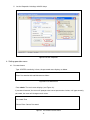
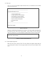
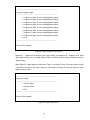
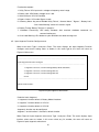
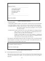
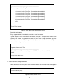
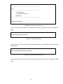
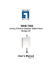
1
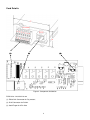
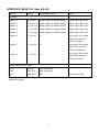
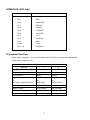
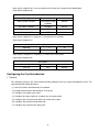
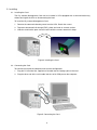
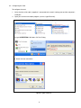
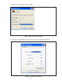
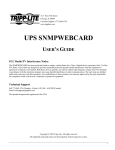
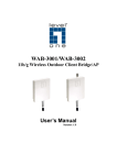
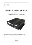
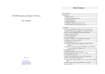
User's Guide
Getting Started
This chapter explains:
• Packing the card
• Installation Checklist
• Card defaults
• INTERFACE (EK381V4L 14pin & RJ45)
• Cable RJ45 TO DB9 (F)
• INTERFACE (UPS side)
• Dry contact Function
• Configuring the Card Introduction
Packing the Card
- Dry contact Management Card
- Screw
- RJ45 to DB9 cable (for RS232, P/N 720-60679-00)
- USER MANUAL
- Safety Cover
- Carton
Figure 1. Dry contact Management Card Package Contents
1
Card Details
Figure 2. Component distribution
PCBA Size: 146.2*60*1.6 mm
(1) EK381V4L Connector for Dry contact
(2) RJ45 Connector for RS232
(3) Gold Finger for UPS Side
2
INTERFACE (EK381V4L 14pin & RJ45)
Segment
PIN NO
Specification/Function
remark
Segment 1
Pin 9 & Pin 2
240Vac/1A(Max) or 30Vdc/1A(Max)
Output signal , NO or NC
Segment 2
Pin 10 & Pin 3 240Vac/1A(Max) or 30Vdc/1A(Max)
Output signal , NO or NC
Segment 3
Pin 11 & Pin 4 240Vac/1A(Max) or 30Vdc/1A(Max)
Output signal , NO or NC
Segment 4
Pin 12 & Pin 5 240Vac/1A(Max) or 30Vdc/1A(Max)
Output signal , NO or NC
Segment 5
Pin 13 & Pin 6 240Vac/1A(Max) or 30Vdc/1A(Max)
Output signal , NO or NC
Segment 6
Pin 8 & Pin1
Input signal (The external
Dry contact
NA
contact must be closed
between pin8&pin1)
Segment 7
Input signal (The external
Pin 14 & Pin1 NA
contact must be closed
between pin14&pin1)
Segment 8
Pin 7 & Pin1
Input signal (The external
NA
contact must be closed
between pin7&pin1)
RS232 (CABLE RJ45 TO DB9F)
TXD2
RJ45, Pin 3
12Vdc 3mA (Max)
RXD2
RJ45, Pin 6
12Vdc 5mA (Max)
GND
RJ45, Pin 4
GND
Power system GND
Segment illustration:
3
Note:
Segment 7 (PIN14 & PIN1 / USER SW2) is fixed to UPS On function.
Segment 8 (PIN7 & PIN1 / USER SW3) is fixed to UPS Off function.
(Refer to Dry contact Function Section at next page of this document)
We Suggest User do not push down USER SW2 and SW3 at the same time.
If user pushes down USER SW2, AS400 Card will send a UPS On command to UPS.
If user pushes down USER SW3, AS400 Card will send a UPS Off command to UPS.
If USER SW2 and SW3 pushed down at the same time,
AS400 Card will first send UPS On command to UPS, then send UPS Off command to UPS.
And the UPS always follow the last command.
CABLE RJ45 TO DB9 (F)
WIRING TABLE
RJ45
DB9
3
------------------
2
4
------------------
5
6
------------------
3
4
Figure 3. RS232 Cable
INTERFACE (UPS side)
Item
Specification/Function
Pin Assignment
- Pin 1
GND
- Pin 2
SNMPPOW
- Pin 3
RXDUPS
- Pin 4
TXDUPS
- Pin 5
*UNUSED*
- Pin 6
*UNUSED*
- Pin 7
-VCC
- Pin 8
SNMPSIG
- Pin 9
GND
- Pin 10
+VCC
- Pin 11~26
RESERVE
Dry contact Function:
Output signals (Segment 1~5): User can choose one function for a Segment from below table.
*Output signal (Segment 1~5):
Description
Meaning
“1”
“0”
Utility Fail
Fail
Normal
Battery Low
Battery Low
Normal
General Alarm
Alarm
Normal
Bypass Status (Online UPS)
Bypass Active
Not Bypass Status
Or
Or
Or
AVR Status (Offline/LIA UPS)
AVR Active
Not AVR Status
Summary Alarm
Alarm
Normal
Battery Testing
In test mode
Not test mode
Shutdown Processing
UPS Shutdown
Normal
Over Load Warning
Over Load
Normal
5
Input signals (Segment 6): User can choose one function for a Segment from below table.
*Input signal (Segment 6):
Description
Meaning
“1”
Battery mode shutdown
Only Battery mode
“0”
Normal
shutdown
Any mode shutdown
Shutdown
Normal
Emergency power off
OFF
Normal
Remote On/Off
OFF
ON
Input signals (Segment 7): Segment 7 is fixed to UPS On function.
*Input signal (Segment 7):
Description
Meaning
“1”
UPS On
ON
“0”
Normal
Input signals (Segment 8): Segment 8 is fixed to UPS Off function.
*Input signal (Segment 8):
Description
Meaning
“1”
UPS Off
OFF
“0”
Normal
Configuring the Card Introduction
1. General
This document specifies the Serial communication protocol of the Dry contact Management Card. The
card provided the following features.
(1) Get UPS internal information by SCI protocol
(2) Bridge communication data between PC and ups
(3) Configure five output relay signal
(4) Configure one input signal for shutdown ups or remote on/off
(5) Configure Dry contact normal open and normal close status
(6) Configure Dry contact function definition
(7) Configure Dry contact active delay time
6
2. Definitions
2.1. Common items
(1) Computer (Software) has Initiative for communicate by this protocol.
Computer will send command ended with <cr>.
Dry contact Management Card will respond the information of ended with <cr>
Note : <cr> means ASCII code “Carriage Return” (HEX-code 0D).
(2) All the information is provided in ASCII format.
(3) Communication start timing
Dry contact Management Card should be received the command from PC, and send the right
response to PC.
2.2. Serial Data format
Dry contact Management Card data will be provided at 2400 baud rate and consist of 1 start bit, 8 data
bits, no parity, and 1 stop bit.
BAUD RATE:
2400 band
DATA LENGTH: 8 bits
STOP BIT:
1 bit
PARITY:
NONE
Data format figure:
Start
b0
b1
b2
b3
7
b4
b5
b6
b7
Stop
3. Installing
3.1. Installing the Card
The Dry contact Management Card can be installed in UPS equipped with a communication bay
without turning off the UPS or disconnecting the load.
To install the Dry contact Management Card:
1. Remove the communication bay cover from the UPS. Retain the screws.
2. To prevent electrostatic discharge (ESD), place one hand on a metal surface.
3. Slide the card into the open slot and secure with the screws removed in Step 1
Figure4. Installing the Card
3.2. Connecting the Card
To connect the card to the computer and start the configuration:
1. Plug the RJ-45 end of the supplied serial cable into the Settings port on the card
2. Plug the other end of the serial cable into the serial COM port on the computer.
Figure5. Connecting the Card
8
3.3. Configuring the Card
To configure the card:
1. Verify that the serial cable (supplied) is connected to the card's Settings port and the computer's
COM port.
2. Open your terminal emulation program (such as HyperTerminal).
a. StartÆAll ProgramsÆAccessoriesÆCommunicationsÆHyper Terminal
Or type HYPERTRM in Windows OS Run Dialog
b. Name the new connection
Figure6. Hyper Terminal
9
3. Select the serial connection (such as COM1).
Figure7. Select the serial connection
4. Set the serial line to 2400 baud, 8 data bits, No parity, 1 stop bit, no flow control.
Figure8. Configuring Port Settings
10
5. Set the PropertiesÆSettingsÆASCII Setup.
Figure9. Set the Properties
4. Setting operation menu
4.1. Password menu
Type <ENTER> continuity 3 times, the password menu displays as below
Enter Password to Activate Maintenance Menu:
Figure10. Password menu
Enter admin. The main menu displays (see Figure 12).
If password incorrect, the menu will prompt enter correct password as below, until type correctly
password, the menu will change to main menu
Password Error
Please Enter Correct Password:
Figure11. Password incorrect menu
11
4.2. Main menu
There are six item can be setting or inquire firmware version, user need base on menu number
and enter the correct menu
----------------------------------------------------------------------------Dry contact Management Card
----------------------------------------------------------------------------1. Function Segment Logic
2. Output Segment Function Configure
3. Input Segment Function Configure
4. Function Segment Active Delay Time
5. Return to Default Configuration
6. Firmware Version
0. Exit
----------------------------------------------------------------------------Please Enter Number:
Figure12. Main menu
Type any list number then will change to 4.3~4.9 menu, if user enter number not include of list,
the window will show “Please Enter Correct Number:” string as below, this menu will possible
show in any setting menu, if user do not depend on prompt number and enter a wrong number
Please Enter Correct Number:
Figure13. Un-correct number prompt menu
4.3. Function Segment Logic menu
When main menu Type 1 and press Enter. The menu displays the Segment settings logic and
current setting status as below, in this menu type 0 number, the menu will return to Figure12. Main
menu.
12
----------------------------------------------------------------------------Function Segment Logic
----------------------------------------------------------------------------1. Segment 1 Logic, Current Setting(Normal Open)
2. Segment 2 Logic, Current Setting(Normal Open)
3. Segment 3 Logic, Current Setting(Normal Open)
4. Segment 4 Logic, Current Setting(Normal Open)
5. Segment 5 Logic, Current Setting(Normal Open)
6. Segment 6 Logic, Current Setting(Normal Open)
7. Segment 7 Logic, Current Setting(Normal Open)
8. Segment 8 Logic, Current Setting(Normal Open)
0. Exit
----------------------------------------------------------------------------Please Enter Number:
Figure14. Logic Segment select menu
Segment 1 ~ Segment 5 for output signal logic setting, and Segment 6 ~ Segment 8 for input
signal logic setting, user can setting “Normal Open” and “Normal Close” type, the default setting is
“Normal Open”
When Figure14. Logic Segment select menu Type 1~6 and press Enter. The menu displays Logic
select menu as below, in this menu select any list number, the menu will return to Figure14. Logic
Segment select menu
----------------------------------------------------------------------------Segment 1 Logic
----------------------------------------------------------------------------1. Normal Open
2. Normal Close
0. Exit
----------------------------------------------------------------------------Please Enter Number:
Figure15. Logic select menu
13
4.4. Output Segment Function Configure menu
When main menu Type 2 and press Enter. The menu displays the Output Segment Function
Configure and current setting status as below, in this menu type 0, the menu will return to
Figure12. Main menu
----------------------------------------------------------------------------Output Segment Function Configure
----------------------------------------------------------------------------1. Segment 1 function, Current Setting(Utility Failure)
2. Segment 2 function, Current Setting(Battery Low)
3. Segment 3 function, Current Setting(General Alarm)
4. Segment 4 function, Current Setting(Bypass Status)
5. Segment 5 function, Current Setting(Summary Alarm)
0. Exit
----------------------------------------------------------------------------Please Enter Number:
Figure16. Output Segment select menu
Default of each Segment
1. Segment 1 function default is Utility Failure
2. Segment 2 function default is Battery Low
3. Segment 3 function default is General Alarm
4. Segment 4 function default is Bypass Status
5. Segment 5 function default is Summary Alarm
When Figure16. Output Segment select menu Type 1~5 and press Enter. The menu displays
output function select menu as below, in this menu select any list number, the menu will return to
Figure16. Output Segment select menu
----------------------------------------------------------------------------Segment 1 Function
----------------------------------------------------------------------------1. Utility Failure
2. Battery Low
3. General Alarm
4. Bypass Status
5. Summary Alarm
6. Battery Testing
7. Shutdown Processing
8. Over Load Warning
0. Exit
----------------------------------------------------------------------------Please Enter Number:
Figure17. Output function select menu
14
Function description:
1. Utility Failure: UPS input mains voltage or frequency out of range
2. Battery Low: UPS Battery voltage level is low
3. General Alarm: UPS fail condition
4. Bypass Status: UPS under Bypass mode
5. Summary Alarm: Any one of AS400 “Utility Failure”, “General Alarm”, ”Bypass”, “Battery Low”,
“Over Load Warning” active will send this signal
6. Battery Testing: Battery Testing is in progress
7. Shutdown Processing: UPS doing shutdown after received shutdown command via
communication port
8. Over Load Warning: UPS load over spec definition over load warning level
4.5. Input Segment Function Configure menu
When main menu Type 3 and press Enter. The menu displays the Input Segment Function
Configure and current setting status as below, in this menu type 0, the menu will return to
Figure12. Main menu
! "
#
$%&
'
$%&
()*
%+,)
-./
Figure18. Input Segment select menu
Default of each Segment
1. Segment 6 function default is Battery Mode Shutdown
2. Segment 7 function default is UPS On
3. Segment 8 function default is UPS Off
Segment 6 function can be configured.
Segment 7 and 8 function is fixed to its default function.
When Figure18. Input Segment select menu Type 1 and press Enter. The menu displays input
function select menu as below, in this menu select any list number, the menu will return to
Figure18. Input Segment select menu
15
----------------------------------------------------------------------------Segment 6 Function
----------------------------------------------------------------------------1. Battery Mode Shutdown
2. Any Mode Shutdown
3. Emergency Power Off
4. Remote On/Off
0. Exit
----------------------------------------------------------------------------Please Enter Number:
Figure19. Input function select menu
Function description:
1. Battery Mode Shutdown: If Signal is active and UPS is under bat mode, UPS will cutoff output
2. Any Mode Shutdown: If Signal is active and UPS is under any mode, UPS will cutoff output
3. Emergency Power Off: If Signal is active and UPS is under any mode, UPS will cutoff output,
give out EPO warning, and pressing any button on UPS LCD panel
can not turn on UPS.
4. Remote On/Off: If Signal is active (close Pin 8 & Pin1 when Segment 6 is configured to Normal
Open; or open Pin 8 & Pin1 when Segment 6 is configured to Normal Close )
and UPS is under any mode, UPS will cutoff output.
If Signal is not active (open Pin 8 & Pin1 when Segment 6 is configured to
Normal Open; or close Pin 8 & Pin1 when Segment 6 is configured to Normal
Close ) and UPS is under any mode, UPS will turn on.
When Figure18. Input Segment select menu Type 2 or 3 and press Enter, it will reject the number
because Segment 7 or 8 function is fixed. User only can type 1 to set Segment 6 function. If user
type 0, the menu will return to Figure12. Main menu
This Segment Function can not be set.
Please Enter a Number again:
Figure20. Segment function can not be set
4.6. Function Segment Active Delay Time menu
When main menu Type 4 and press Enter. The menu displays the Function Segment Active Delay
Time and current setting value as below, in this menu type 0, the menu will return to Figure12.
Main menu
16
----------------------------------------------------------------------------Function Segment Active Delay Time
----------------------------------------------------------------------------1. Segment 1 Active Delay Time, Current Setting(Immediately)
2. Segment 2 Active Delay Time, Current Setting(Immediately)
3. Segment 3 Active Delay Time, Current Setting(Immediately)
4. Segment 4 Active Delay Time, Current Setting(Immediately)
5. Segment 5 Active Delay Time, Current Setting(Immediately)
6. Segment 6 Active Delay Time, Current Setting(Immediately)
0. Exit
----------------------------------------------------------------------------Please Enter Number:
Figure21. Active delay time Segment select menu
Default of each Segment
Every Segment default is immediately, enter 00 is means immediately
Type 00 and press Enter means active Immediately, and type 01 and press Enter means active
will delay one second, only type one character and press Enter is illegal command, only press
Enter means user do not want to change the setting parameter and menu will return to Figure21.
Active delay time Segment select menu
----------------------------------------------------------------------------Segment 1 Active Delay Time
----------------------------------------------------------------------------Please Enter Delay Time 00~99, Only Press <ENTER> Means Abort and Exit Current
Setting
Please Enter Delay Time:
Figure22. Active delay time menu
4.7. Return to Default Configuration menu
When main menu Type 5 and press Enter. The menu displays the Return to Default Configuration
as below
Return to Default(Y/N)?:
Figure23. Default confirm menu
17
Enter Y or y. below menu will display as below, if enter any other character, the only main menu
displays (see Figure 12) and not show “Default All Configuration Parameter” string and do not
change to default value
Default All Configuration Parameter
----------------------------------------------------------------------------Dry contact Management Card
----------------------------------------------------------------------------1. Function Segment Logic
2. Output Segment Function Configure
3. Input Segment Function Configure
4. Function Segment Active Delay Time
5. Return to Default Configuration
6. Firmware Version
0. Exit
----------------------------------------------------------------------------Please Enter Number:
Figure24. Default all configuration parameter success menu
4.8. Firmware Version menu
When main menu Type 6 and press Enter. The menu displays the Firmware Version and
development data as below, in this menu type 0, the menu will return to Figure12. Main menu
----------------------------------------------------------------------------Firmware Version
----------------------------------------------------------------------------Firmware Version:00.05 2010/06/01
0. Exit
----------------------------------------------------------------------------Please Enter Number:
Figure25. Firmware version menu
4.9. Exit menu
When main menu Type 0 and press Enter. The menu displays the Exit setting mode information
as below
18
----------------------------------------------------------------------------Exit
----------------------------------------------------------------------------1. Exit and Save
2. Exit and Without Save
0. Not Exit
----------------------------------------------------------------------------Please Enter Number:
Figure26. Exit and save select menu
Type 1 and press Enter means exit setting mode and Save change data, the menu string will as
below
Exit Setting Mode and Save Data
Figure27. Exit and Save menu
Type 2 and press Enter means exit setting mode and without save change data, the menu string
will as below
Exit Setting Mode and Without Save Data
Figure28. Exit and Without Save menu
Type 0 and press Enter means still stay on setting mode, the menu will return to Figure12. Main
menu
19
614-09976-00
20