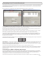
1
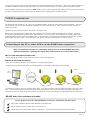
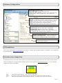
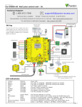
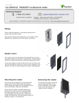
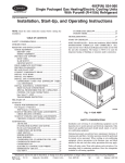
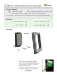
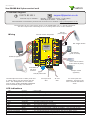
30/08/2012
Paxton
Ins-30080 Net2 plus control unit
Technical Support
[email protected]
01273 811011
Technical help is available:
Monday - Friday from 07:00 - 19:00 (GMT)
Saturday from 09:00 - 13:00 (GMT)
Documentation on all Paxton products can be found on our website - http://www.paxton.co.uk/
The Net2 plus can be connected to the PC via an RS485 data line or a TCP/IP connection.
This unit requires the controlling PC to be running Net2 v4.14 or later software.
12V DC
power supply
Intruder alarm integration
Power
0V
Arm
COM
Set
Intruder Alarm
0V
12V
Red LED
Amber LED
Data/D0
Reader 2
Green LED
123456
LABEL
HERE
00-01-02-03-04-05
N.O.
Alarm
Exit button
(push to make)
Green LED
Exit
0V
End of Line Termination
OFF
ON
Server Connected
Tx
Rx
Orange
Green
Wht/Orng
10/100 Ethernet
RS485 Network
CAT5 Cable Coding
Wht/Grn
10
Server Link
100
Contact
0V
0V
Tamper
PSU
Switchable
120 ohm
resistors
From previous
ACU
Door contact switch
(held closed by door)
Tamper switch
(optional)
TCP/IP patch lead
The Net2 plus ACU has 2 reader ports and
3 output relays, but can control just one
door. The configuration of one control
unit per door greatly simplifies installation
and is ultimately highly cost effective.
*
N.C.
12V
Screen or spare
cores from data
cable
0V
Fail closed release
N.O.
COM
Clock/D1
Media Detect
0V
0V
COM
Exit Button
Media Detect
Caution: For 12V DC readers only
Clock/D1
2345612
Inputs
Data/D0
Relay 1
http://paxton.info/107
Outputs
Green LED
12V
N.C.
Relay 2
Net2 plus
Reader 1
Amber LED
Contact
Red LED
Reader/keypad
Sense
12V
N.O.
Expansion
PSU/Tamper
Wiring
To next
ACU
For a fail open lock
(Maglock), wire 0V to the
"N.C." terminal instead of
"N.O."
LED indications
12V
Relay 1
Relay 2
Alarm
Exit
Contact
Tamper
PSU
(Green)
(Orange)
(Orange)
(Red)
(Orange)
(Orange)
(Orange)
(Orange)
OK
(Green flash)
Termination
(Red)
Rx
(Red)
Tx
(Green)
Server Connected (Green)
Server Link
-
Power LED.
The relay is energised - (N.O./COM contacts are closed).
The relay is energised - (N.O./COM contacts are closed).
12V Alarm output is active.
The exit button contacts are closed.
The door contacts are closed.
The tamper contacts are closed.
The PSU contacts are closed.
-
The internal software is running.
The on-board resistors are in place across the RS485 data pairs.
The ACU is receiving data (TCP/IP or RS485) - See also FAQ section.
The ACU is responding to data - (TCP/IP or RS485).
The TCP/IP interface is communicating with the PC Net2 server.
Green = 100 Mbit/s : Orange = 10 Mbit/s (TCP/IP speed).
Page 1
Overview
A Net2 plus can connect to the Net2 PC using either an un-shielded RJ45 patch cable or an RS485 data line. This
greatly increases the number of installation options available to the installer.
One Net2 plus can also be used as the TCP/IP interface for an RS485 daisy chain of Net2 plus and Net2 classic units.
When used with a TCP/IP connection, it must first be detected using the Net2 Server Configuration Utility. See later
section of this instruction and AN1006 - Installing remote sites using TCP/IP < http://paxton.info/51 >
When used with an RS485 data line, on-board termination resistors can be put in circuit with a simple slide switch.
Ensure that units installed in the middle of the data line have this switch turned OFF.
A dedicated Intruder Alarm connection is provided.
Site Layout Examples
Media Detect
0V
Power
Relay 1
Outputs
Relay 2
N.C.
Exit Button
Inputs
End of Line Termination
OFF
ON
Clock/D1
0V
Server Connected
10
100
RS485 Network
CAT5 Cable Coding
Tx
Rx
Green
Server Link
10/100 Ethernet
Orange
PSU
N.C.
N.O.
COM
N.O.
COM
Green LED
Exit
0V
Contact
Green LED
Data/D0
0V
Tamper
0V
Alarm
PSU/Tamper
Power
Relay 1
Outputs
Relay 2
Exit Button
Contact
Inputs
Amber LED
0V
PSU/Tamper
Power
Relay 1
Outputs
Relay 2
Exit Button
Inputs
Contact
Power
Relay 1
Outputs
Relay 2
Exit Button
Inputs
Contact
Power
Relay 1
Outputs
Relay 2
Exit Button
Inputs
Contact
Power
Relay 1
Outputs
Relay 2
Exit Button
Inputs
Contact
Exit
Contact
12V
12V
Wht/Grn
Green
PSU/Tamper
Rx
Red LED
Wht/Orng
PSU/Tamper
Tx
0V
12V
Green LED
PLACE SERIAL
NUMBER
LABEL HERE
Screen or spare
cores from data
cable
PSU/Tamper
OFF
RS485 Network
CAT5 Cable Coding
Orange
10
100
Wht/Grn
Server Link
Intruder Alarm
Net2 plus
Reader 2
End of Line Termination
Server Connected
10/100 Ethernet
Wht/Orng
Green
Orange
Wht/Grn
Wht/Orng
0V
Set
Red LED
Amber LED
Green LED
Data/D0
Clock/D1
Media Detect
Caution: For 12V DC readers only
Media Detect
N.C.
N.O.
COM
Alarm
ON
Clock/D1
0V
N.O.
COM
Reader 1
Green LED
Data/D0
0V
PSU
0V
Amber LED
0V
Tamper
COM
Exit
Contact
N.O.
Rx
12V
0V
12V
Screen or spare
cores from data
cable
Tx
Red LED
Sense
RS485 Network
CAT5 Cable Coding
Screen or spare
cores from data
cable
Orange
Green
10
100
0V
12V
Green LED
12V
N.C.
PLACE SERIAL
NUMBER
LABEL HERE
Arm
OFF
ON
Server Link
Intruder Alarm
Net2 plus
Reader 2
End of Line Termination
Server Connected
10/100 Ethernet
Set
Red LED
Amber LED
Green LED
Data/D0
Clock/D1
Media Detect
Alarm
Media Detect
0V
N.C.
N.O.
COM
Caution: For 12V DC readers only
Data/D0
N.O.
COM
12V
Clock/D1
0V
12V
Reader 1
Green LED
0V
PSU
0V
Amber LED
0V
Tamper
COM
Exit
Contact
N.O.
Rx
Sense
Tx
Arm
OFF
RS485 Network
CAT5 Cable Coding
Wht/Grn
10
100
Wht/Orng
Green
Orange
Server Link
10/100 Ethernet
Reader 2
Server Connected
0V
Red LED
0V
Net2 plus
Expansion
12V
N.C.
PLACE SERIAL
NUMBER
LABEL HERE
Caution: For 12V DC readers only
Media Detect
Reader 1
Clock/D1
0V
0V
12V
Green LED
0V
End of Line Termination
ON
0V
PSU
Intruder Alarm
Net2 plus
Clock/D1
Media Detect
Net2 plus
Expansion
Set
Red LED
Amber LED
Green LED
Data/D0
COM
Green LED
Data/D0
12V
2
N.O.
Amber LED
0V
Tamper
N.C.
N.O.
COM
Sense
Exit
Contact
N.O.
COM
Alarm
Expansion
12V
Arm
Rx
PLACE SERIAL
NUMBER
LABEL HERE
Screen or spare
cores from data
cable
Tx
Red LED
Reader 2
OFF
RS485 Network
CAT5 Cable Coding
Wht/Grn
10
100
Wht/Orng
Green
Orange
Wht/Orng
Wht/Grn
Server Link
10/100 Ethernet
12V
Green LED
0V
N.C.
Net2 plus
0V
Caution: For 12V DC readers only
End of Line Termination
Server Connected
0V
Clock/D1
Media Detect
12V
Intruder Alarm
Red LED
Amber LED
Green LED
Data/D0
N.O.
Reader 1
Media Detect
N.C.
Set
COM
12V
ON
Clock/D1
0V
0V
Green LED
Data/D0
0V
PSU
COM
Amber LED
0V
Tamper
N.O.
Exit
Contact
Sense
Rx
N.O.
COM
Alarm
Screen or spare
cores from data
cable
Tx
Red LED
PLACE SERIAL
NUMBER
LABEL HERE
Arm
RS485 Network
CAT5 Cable Coding
Screen or spare
cores from data
cable
10
100
0V
OFF
ON
Server Link
12V
Green LED
Reader 2
End of Line Termination
Server Connected
10/100 Ethernet
Arm
0V
Caution: For 12V DC readers only
Clock/D1
Media Detect
12V
Clock/D1
0V
Data/D0
N.O.
COM
12V
0V
N.C.
Net2 plus
Amber LED
Green LED
N.C.
12V
Intruder Alarm
Red LED
N.O.
COM
Alarm
Media Detect
Set
Reader 1
Reader 2
Caution: For 12V DC readers only
Amber LED
Green LED
Data/D0
PLACE SERIAL
NUMBER
LABEL HERE
COM
Reader 1
12V
Red LED
12V
N.C.
Net2 plus
0V
N.O.
0V
Net2 plus
Net2 plus
Expansion
12V
Intruder Alarm
Red LED
Amber LED
Green LED
Data/D0
Clock/D1
Sense
Expansion
Set
Media Detect
Net2 plus
0V
COM
N.O.
Sense
12V
Arm
1
Expansion
PSU/Tamper
Net2 plus
Contact
0V
0V
Tamper
PSU
RS485 data line
TCP/IP
LAN
TCP/IP
LAN
TCP/IP
LAN
TCP/IP
LAN
Here are three typical site layouts.
Power
Relay 1
Relay 2
CAUTION: for 12v d.c. readers only. For
correct connection of old 5v readers, refer to
instructions.
N.O.
0v
0v
Inputs
Power
Relay 1
Outputs
Relay 2
Exit Button
Inputs
Contact
Power
Relay 1
Outputs
Relay 2
Exit Button
Inputs
Contact
N.C.
Contact
4
PSU/Tamper
0v
N.C.
N.O.
Com
Com
Exit
0v
Tamper
PSU
5v
OK
12v
Tx
Rx
Exit
PSU
Tamper
Orange
Relay 2
White/Orange
Relay 1
Green
Contact
TCP/IP
LAN
24898 00000
White/Green
4
+12v
Alarm Output
Network
Green
RS485 data line
3
Screen or spare cores
from network cable
2
3
Brown
Orange
1
CAT5 cable coding
0V
PSU
1 - The Net2 plus ACU's can be individually connected to
the Net2 PC via the site LAN network.
Red
Yellow
0V
Tamper
Keypad 1
0V
Contact
Orange
Reader 1
Rx
Serial number
241821
Tx
Test ID: 012345678901
OFF
RS485 Network
CAT5 Cable Coding
Orange
10
100
Wht/Grn
Green
Orange
Wht/Grn
Server Link
Reader 2
z-1440
Server Connected
10/100 Ethernet
Brown
End of Line Termination
ON
0V
Blue
Data/D0
Clock/D1
Media Detect
Blue
Brown
Yellow
0V
PSU
Green
Yellow
Black/White
Exit
Mauve
0V
Tamper
Keypad 2
Red 12v dc
Brown
Orange
Mauve
Green LED
Green
Green LED
0V
Contact
Wht/Orng
Rx
Screen or spare
cores from data
cable
Tx
Wht/Orng
10/100 Ethernet
RS485 Network
CAT5 Cable Coding
Screen or spare
cores from data
cable
10
100
N.C.
N.O.
COM
Yellow
OFF
ON
Server Link
Reader 2
End of Line Termination
Server Connected
Red LED
Amber LED
Exit
N.O.
COM
Alarm
12V
Black/White
12V
Green LED
0V
N.C.
PLACE SERIAL
NUMBER
LABEL HERE
Caution: For 12V DC readers only
0V
12V
12V
Orange
Reader 1
Reader 2
Caution: For 12V DC readers only
Clock/D1
Media Detect
Net2 classic
0V
Intruder Alarm
Net2 plus
Amber LED
Green LED
Data/D0
COM
Reader 1
N.C.
N.O.
COM
Clock/D1
N.O.
Set
Red LED
N.O.
COM
Sense
12V
0V
Alarm
Media Detect
0V
12V
N.C.
PLACE SERIAL
NUMBER
LABEL HERE
Arm
0V
12V
Red LED
Amber LED
Green LED
COM
N.O.
Intruder Alarm
Net2 plus
0V
Net2 plus
Expansion
Set
Clock/D1
Media Detect
Data/D0
Sense
12V
Red LED
Amber LED
Green LED
Data/D0
Arm
3
Expansion
PSU/Tamper
Net2 plus
2 - The Net2 plus ACU's can be hardwired on a daisy
chain RS485 data line with ONE of them connected to
the Net2 PC via the site LAN network.
3 - The Net2 plus ACU can be used as the TCP/IP
converter for a line of Net2 plus and Net2 classic ACU's.
The TCP/IP interface allows an RS485 data line to be controlled by the Net2 Server running across a LAN network.
An RS485 data line has a 1 km maximum length. This distance can be increased by using Paxton high speed
repeaters or by using shorter independant data lines using multiple LAN connections controlled from the same PC.
Control unit installation
Wire the components to the Access Control Unit (ACU) as shown on the first page. Power up the unit and wait for
the OK heartbeat.
Press the exit button or in the absence of an exit button, short the 0V and exit terminals together. The lock relay
LED will come on and the lock should release.
The reader's default indication has all the LED's on. Access granted is denoted with a single flashing Green LED.
Access Denied is a single flashing Red LED.
Remember, the Net2 plus is a combined TCP/IP interface and an Access Control unit. If the TCP/IP interface is
being used, you will need to detect the interface first using the procedure on the following page.
This is important if you are replacing an existing Net2 plus. The Replace wizard in the Doors screen does NOT
reconfigure the IP address so it must be done manually. The wizard will then copy across the user data.
Each time the unit is powered on, it will run an internal health check. During this phase (about 5 secs) the OK
LED will flash quickly before changing to a slower heartbeat.
Page 2
Connecting to the PC via the Ethernet port
The IP address should be assigned a fixed value, or should be given a DHCP reservation. Unreserved IP addresses
issued by DHCP servers are not guaranteed to be constant, leading to potential failure of communication between
Net2 software and the device.
Run the Net2 Server Configuration Utility (Start/Programs/Net2) and Click on TCP/IP nodes.
Click on;Detect and the MAC address of the device(s) will appear in the table. You must then use the "IP address
configuration" tab to manually assign the IP address, subnet mask and gateway.
Be aware that if the IP address that you give the device is not in the same IP range as the PC, the device will no
longer respond until you connect to it with a PC that is in the same IP range.
Some firewall/virus protection software and other wireless hardware can block the IP detection process. Disable
these and try to detect the device again. Please contact Technical Support if you require further advice.
If you detect the MAC address but the device now shows 'Not Responding', you must check the IP address, to
make sure it is still in range with the PC or network. If it is not, you should either change the IP address of the
PC or the IP address of the device so they are both again in the same range. Our Technical team can talk you
through this if you need help.
If the MAC address does not appear when you click;Detect, ensure that the following ports are open on all devices
between this unit and the Net2 PC:69
UDP
10001
TCP
30718
UDP
TCP/IP Reset - The unit can be returned to DHCP settings by powering down the unit and linking the Brown and
Mauve terminals on reader port 2. Power up the unit again and the unit will beep to acknowledge the link. You
may now remove the link and the OK LED will flash fast for a few seconds. When the OK LED returns to a steady
heartbeat, the IP settings will be reset to DHCP.
If you still cannot detect the MAC address of the device, call our Technical Support Help line.
The device will 'beep' when detected by the Net2 Server Configuration Utility or when new IP settings are applied.
The sounder will also respond to a direct 'Ping' over the network. This is a feature to assist with finding devices
hidden from view.
Connecting to a WAN or different subnet mask
If you are connecting this device to a remote subnet which is different from the Net2 software PC, the standard
detect mechanism cannot work across the network routers between them. The IP address, along with the correct
subnet mask and gateway for the remote subnet have to be set. Either do this on the local subnet with the
existing Net2 PC, or use a PC on the remote subnet once the device is installed.
The PC that has the Net2 server installed must be able to access the IP address range on the WAN/remote site.
Page 3
This may require the routers and gateways to be configured between the networks. Again, this would be done by
the Network administrator of that site. Make sure the ports listed above are open on all intermediate routers.
Once installed, create a record with the;Add button (if none was created during initial set up) and you should then
be able to detect its MAC by entering the IP address in the Configuration screen Ping box.
TCP/IP Loopback test
The following test should be run if there are problems setting up the IP configuration of the interface. This test
sends data to the device and checks this against the data it receives back. This confirms that the network is
working correctly.
The Net2 server program must be shut down during this test.
Remove any wires from the RS485 data line connector and create a hardwired data loop as follows. Connect
the Orange to White/Green and Green to White/Orange. To run the test, go to Net2 Server Config Utility/TCP/
IP Nodes/Advanced and click on Loopback test. If the test fails, connect the unit directly to the PC with an RJ45
patch cable and test it again. Should this still fail, please call Technical Support for further advice.
Connecting to the PC or other ACU's via the RS485 data connection
90% of installation faults are caused by wiring errors on the RS485 data line.
Special attention to getting this right first time saves a lot of time and effort.
END OF LINE TERMINATION SWITCHES.
- These should all be OFF except for those at both ends of the data line.
READER & DATA CABLE SCREENS.
- Data cable screens and spare cores MUST be connected throughout.
- Reader and keypad screens where provided should be connected to the Black (0V) terminal.
Reader
Net2
Server
Control unit
The data line must be wired in a single daisy chain. The data converter may be located anywhere along the data
line. 120 ohm terminating resistors must be linked across each data pair at the beginning AND end of the line.
This can be done on many units with a switch or jumpers. If not, free resistors are provided with the converter.
RS485 data line resistance checks
Power down all TCP/IP, USB and RS232 converters (individual and Net2 plus).
Check the resistance across each data pair is 60-80 ohms.
Check that there are no data line to screen shorts.
Check the screen of the data cable is continuous - this provides the 0V DC system reference.
Page 4
Software Configuration
Door name: Name the Door.
Door open time: Set the door open time.
Unlock the Door during: Holds the door unlocked during
this timezone. - Set to 'At No Time' for normal user
operation.
Reader 1: Settings for Reader 1 and Keypad 1 on the ACU.
Reader 2: Settings for Reader 2 and Keypad 2 on the ACU.
Alarm: Contains settings for the different types of alarm.
Codes: Valid codes can be viewed, added and removed.
(Can only be viewed when a keypad is active).
Events: Shows the events for the control unit selected.
Name: Each reader can be named individually if required.
Reader type: Set the reader type, if applicable.
Keypad type: Set the keypad type, if applicable.
Token data format: Select the data type being used on
the system. (New formats can be created).
Reader operating mode: Set the operating mode.
Timed operating modes: A different operating
mode can be configured within a time window.
Reader action: Set the action required
when access is granted.
PC Installation
The current specification for compatible PC hardware, network and operating systems is available on our website at
the following link: http://paxton.info/720
Intruder alarm integration
A dedicated port for input and output signals is provided when integrating a Net2 plus ACU with an alarm system.
Please see AN1035 - Integrating Net2 with an intruder alarm system < http://paxton.info/91 > or call Technical
Support for further information.
Arm
Sense
Set
- Confirmation Push Button - Wire across 0V and Arm.
- Requires a voltage free loop across 0V and Sense to confirm when alarm is active.
- Relay provides contacts across COM and N.O. for a voltage free loop to set the alarm.
Page 5
Technical Help
1 - RS485 Data line resistance check - ACU not responding or fails to be detected.
QFirst power down any data line converters and disconnect any ACU's that do not have a flashing OK LED. Using a
QMultimeter, measure the resistance across the White/Green and Green pair at one end of the network.
QA resistance of between 60 and 80 ohms is required. Repeat the test for the White/Orange and Orange pair.
QThis is vital for a stable and trouble free installation.
2 - ACU Reset - No OK LED flashing.
QThe ACU has no factory reset condition as it does not contain any fixed settings. The unit does have an operating
Qprogram (firmware) that controls its functions and can be confirmed as running by means of the flashing OK LED.
Q- If the OK LED is flashing steadily, then there should be no reason to reset the unit.
Q- If the OK LED is not flashing, you need to clear the unit so that it can receive a firmware download from the PC.
Q Any other ACU's without OK LED's must be taken off the line or powered down.
Q1.
Q2.
Q3.
Q4.
Q5.
Q6.
Q
Q
Stop Net2 Server (Net2 server icon - Bottom right of screen - Right mouse click, Select Stop the Net2 Server).
Power down the Net2 ACU.
Insert a link wire between the Orange and Mauve terminals on reader 2 port.
Power up the ACU. - The OK LED flashes very quickly.
With the unit still powered, remove the link.
Go to the PC and Start the Net2 Server and go into the Doors screen. Click on the Detect button. This
should look for the ACU and then download its firmware (This may take up to 5 minutes). - The OK LED
should now be flashing with a steady heartbeat. This procedure must only be done for one ACU at a time.
Q NOTE: If this unit is using the TCP/IP interface, any fixed IP settings will be retained.
Q If the unit is in DHCP mode it will need to be detected at each stage using the Net2 Server Config Utility
Q as a new address may be issued by the IP server, each time the PCB resets.
3 - Can we use a DHCP IP address?
QThe Ethernet interface does support DHCP, but for more reliable communication, a static IP address must be
Qreserved for the unit. This is because some servers issue different DHCP addresses each time they are restarted
Qand this requires the Net2 interface to be manually set up again - a time consuming process.
4 - TCP/IP - Direct PC connection.
QConnect the network interface directly to the LAN port of the PC. Without the presence of a DHCP server the unit
Qwill default to an IP address in the range 169.254.X.X.
QCheck the IP address of the network card of your PC by typing IPCONFIG at the command prompt. Detect the
QTCP/IP interface with the Net2 Server Configuration Utility and change the IP address to an address
Qsimilar to that of your machine. For example, if the IP address of the PC is 192.168.10.7, change the IP address
Qof the TCP/IP interface to 192.168.10.8. Once the IP address of the interface has been changed into the range of
Qthe PC then Net2 will be able to communicate with it.
QNOTE: Do not change the IP address of your PC to 169.254.x.x, this will not allow the IP address of the TCP/IP
Qinterface to be fixed correctly.
5 - Cannot detect ACU via a TCP/IP interface.
Q1.
Q
Q2.
Q3.
The TCP/IP interface must be listed in the Net2 Server Configuration Utility, and responds when PINGed
from the utility. A static IP address must be used for the interface.
If the interface is responding, try a loopback test. (see Loopback section)
The Net2 data line should be checked for resistance readings.
6 - Readers/Keypads not working.
QQQQ
QQQQ
Software settings - Confirm that the settings of the reader or keypad are correct.
Connections - Check the wiring and integrity of the connectors. - If possible, test this reader on the other port.
Cable - Belden 9540 should be used to extend the reader cable (100 m maximum). Twisted pair alarm cable
should not be used. To confirm that a cable extension is not at fault, wire the reader direct into the reader port.
Supply voltage - Confirm that the voltage is within specification. (see table)
User token - Confirm that the user token used for testing is OK by presenting it to a known working reader.
Interference - Confirm whether the reader works when tested 'in hand' and not mounted on the wall. Ensure
that readers are not mounted back to back or there is no interference from other local RF devices.
Page 6
Here is the list of topics about this product that receive the most technical support enquiries.
We list them here to help you speed up the installation and trouble shooting process.
7 - Fire alarm integration - Net2 Professional software must be used.
QA voltage free normally closed contact from the fire alarm system should be wired across an ACU input
Q(Contact/PSU/Tamper/Exit). The doors that are required to open from that trigger are set up in the software for
Qthat ACU under the Fire Alarm Tab.
QNOTE: The doors are relocked from the PC software - resetting the Fire panel will have no effect on the system.
QThe Net2 Server MUST be running at all times for this method to work.
QFail open locks are required on fire doors. Break glasses should be installed to drop power to the lock manually.
8 - RS485 data line cable layout. (Net2 classic and Net2 plus)
QThe data line must be wired in a daisy chain. End of Line (120ohm) resistors must be fitted/switched across
Qboth pairs at each end of the line.
QRepeaters must be used over 1000 metres and can be used to create a branch from the daisy chain. Cat5 or
QBelden 8723 (4 Core Twisted pair) must be used for the data line. The cable screen must be connected
Qthroughout for reliable communication. Cat5 must have spare cores terminated in lieu of screen cable.
9 - Timesheet - Why Time & Attendance must have dedicated readers for logging in/out.
QIn the vast majority of applications using the same reader for access and T&A is not practical. Traffic through the
Qaccess points causes long, unmanageable T&A reports. It is therefore NOT possible to set this up in the software.
QProximity or Cardlock readers set up as Clocking in or Clocking out readers have no effect on Relay 1 and will not
Qappear in Access levels. Relay 2 will switch for half a second to allow confirmation by fitting an LED or sounder.
10 - TCP/IP communication over a WAN.
QWe need to establish two-way communications between a PC on site A and the TCP/IP interface on Site B.
QThe paths that the PC and the TCP/IP interface will use are different, but they each need to know the IP address
Q they are trying to locate on the other site as well as the gateway IP address that will route their requests from
Q their own LAN to the other LAN.
Q- TCP/IP Interface set up (Site B).
QYou need to set the IP address for the TCP/IP interface that will define it within it's own LAN. (e.g. 10.10.0.25).
QYou need to set the gateway IP address of the local 'router', in the TCP/IP interface. This is so that the router will
Q know that any reply from this interface needs to be sent back to the other LAN.
QNOTE: All the information required to get back to the sending PC on site A is done automatically by the network
Q hardware; the 'site A' PC includes its own IP address in the outgoing message.
Q- PC Set up (Site A).
QMost LAN addressing is set up such that different groups are reserved for specific remote sites. It is then just a
Q case of setting up the IP address of the TCP/IP interface on site B (10.10.0.25) in the PCs' Net2 Server
Q Configuration Utility; all the outward routing is done automatically by their network hardware.
QPort '9999' must be allowed through any firewall software.
TCP/IP and RS485 LED indication
The Net2 plus performs two functions. It is an access control unit and also a TCP/IP RS485 converter. Information
can pass across the PCB between the TCP/IP and RS485 data port but is not relevant to this ACU.
- Server Connected LED (Steady Green)
This LED shows that the TCP/IP interface is active and receiving data from the Net2 PC server. This includes all
data for other ACU's that may be linked via the RS485 data port.
- Rx and Tx LED's
These LED's show the activity for this ACU only. This is same indication as seen on a Net2 classic ACU.
It is not dependant on the source (TCP/IP or RS485). The Rx LED will flash for all data being received and the Tx
LED will only flash when this unit responds to its own address.
Page 7
Specifications
Min
Features
Max
Number of Cards
50,000
Net2 v4.16
Number of PIN's
50,000
Net2 v4.16
Access levels
250
Time zones
64
Maximum door open time
1 sec
999,999 sec
50
Number of Codes
Doors per ACU
1
Reader ports per ACU
2
Readers per port
2
Keypads per port
2
ACU per data line
200
Data lines per PC
200
Data retention after total power loss
Events stored in ACU with no server connection
Communication
Ethernet network speed
2,728
Min
Max
10 Mbit/s
100 Mbit/s
200 kbit/s
Ethernet bandwidth requirement
DHCP support (fixed IP recommended)
Yes
RS485 network speed
115.2 kbit/s
Min
Electrical
Voltage
11V DC
Max
15V DC
PCB Current (depending on activity)
200 mA
Relay switchable voltage
24V DC
Relay switchable current
4A
Alarm output current
1A
Combined reader port output current
Environment
Operating temperature - Battery limits
Waterproof
Dimensions
Control Unit
Net2 v4.21
7 days
500 mA
Min
Max
0 °C
+ 55 °C
NO - If used externally, it must be protected in a plastic weatherproof housing
Width
Height
Depth
116 mm
126 mm
25 mm
This product is not suitable for retail sale. All warranties are invalid if this product is not installed by a competent person.
Page 8